3 Readying Oracle Database Appliance for Deployment
This chapter covers the following tasks that you must complete before deploying Oracle Database Appliance software:
-
This task is not required for Oracle Database Appliance Version 1 which has all interconnects and storage connections pre-configured when shipped.
-
Attaching Storage Expansion Shelf
This task is not required for Oracle Database Appliance Version 1 which does not use external storage shelves.
-
This task is only applicable if you have direct access to Oracle Database Appliance and intend to use a locally connected monitor, keyboard, and mouse.
-
The steps in this section apply to your newly-installed Oracle Database Appliance but are also applicable when you need to power it down or add new hardware, such as a storage expansion shelf.
-
Configuring Oracle Integrated Lights Out Manager
Although this is not a required step, or one that you can perform after deployment, Oracle Integrated Lights Out Manager (ILOM) provides alternate ways to restart and troubleshoot Oracle Database Appliance.
-
Configuring Initial Network Connection
To build your network information during deployment, you need a temporary network configuration framework, which this section explains how to configure.
-
Validating Oracle Appliance Manager Software Version
Oracle recommends that you always use the current version of Oracle Database Appliance software if you are deploying or redeploying.
Caution:
Electronic equipment is susceptible to damage by static electricity. Use a grounded antistatic wrist strap, foot strap, or equivalent safety equipment to prevent electrostatic damage (ESD) when you install or service the system.See Also:
-
Oracle Database Appliance Setup Poster for an overview of Oracle Database Appliance setup tasks
-
Oracle Database Appliance Owner's Guide to obtain more detailed hardware installation instructions and safety guidelines
Attaching Supplied Cables
Use Figure 3-1 and Figure 3-2 to guide you as you insert the supplied cables into Oracle Database Appliance models with a single storage shelf. If you are able to distinguish colors, then match cable colors (for the green and yellow cables), or the labels at the ends of each cable, with the colored line shown in the following illustration. Also match the cable colors to the background colors of the socket identification labels. If you are unable to use color coding, then use the callout numbers described in Table 3-1 to complete the cabling for Oracle Database Appliance with a single storage shelf. Because all cables with the same terminations are interchangeable, you can safely ignore the color coding.
Figure 3-1 Interconnects and Cables for Single Storage Shelf on Oracle Database Appliance X5-2
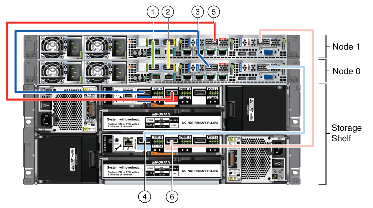
Description of "Figure 3-1 Interconnects and Cables for Single Storage Shelf on Oracle Database Appliance X5-2"
Figure 3-2 Interconnects and Cables for Single Storage Shelf on Oracle Database Appliance X4-2 and X3-2
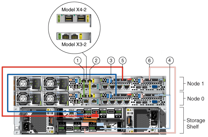
Description of "Figure 3-2 Interconnects and Cables for Single Storage Shelf on Oracle Database Appliance X4-2 and X3-2"
The cables shown in Figure 3-1 and Figure 3-2 and described in Table 3-1 are included with each shipped Oracle Database Appliance. Other than the green and yellow Cat-6 cables, the cables are all black, but have colored labels at each end that match the references to cable colors in the text and the label colors on the back panels.
Note:
The back panel of each node contains three PCIe generation 3 terminal slots, with two sockets in each slot. The PCIe slots are labeled "X PCIe3," where "X" is the PCIe slot number. Table 3-1 identifies these slots as PCIe slot 1, PCIe slot 2, and PCIe slot 3, which matches the numbers on the labels reading from left to right. The storage shelf back panel has two IO modules, one located above the other. Each IO module has three ports, numbered 0, 1, and 2. Table 3-1 identifies these ports as either ”top” or ”bottom” ports, for ports in the upper and in the lower IO module respectively.Table 3-1 Description of Callouts for Cabling Oracle Database Appliance With Single Storage Shelf
| Callout Number from Figure 3-1 and Figure 3-2 | Description |
|---|---|
|
1 |
Green InfiniBand Cable (Oracle Database Appliance X5-2)
Green Cat 6 cable (Oracle Database Appliance X3-2) or green-labelled twinax cable (Oracle Database Appliance X4-2):
|
|
2 |
Yellow InfiniBand Cable (Oracle Database Appliance X5-2)
Yellow Cat 6 cable (Oracle Database Appliance X3-2) or yellow-labelled twinax cable (Oracle Database Appliance X4-2)
|
|
3 |
Dark blue SAS cable:
|
|
4 |
Light blue SAS cable:
|
|
5 |
Dark red SAS cable:
|
|
6 |
Light red SAS cable:
|
Caution:
Do not attach cables to ethernet ports in the I/O modules labeled "SERVICE ONLY" when cabling the system. These ports are intended for use by service engineers only. You must use Oracle Appliance Manager to manage Oracle Database Appliance storage.See Also:
Oracle Database Owner's Guide for details about cabling with the supplied Cable Management Arm.For Oracle Database Appliance X4-2 and X5-2 installations, if you wish to use fiber connections between Oracle Database Appliance and your public network, the interconnect must be cabled using the green and yellow copper ports as shown in callouts 1 and 2 in Figure 3-3. For Oracle Database Appliance X5-2 you must replace the InfiniBand cards with 10GbE SFP+ (fiber) cards, because fiber ports do not exist in the base configuration. After the PCIe cards are replaced, the Oracle Database Appliance X5-2 must be re-imaged. Refer to the Oracle Database Appliance Service Manual for instructions on replacing PCIe cards. Note that the rear panel of Oracle Database Appliance X5-2 is slightly different from that shown in Figure 3-3 but the interconnect cabling is the same.
Figure 3-3 Interconnects When Using Fiber Connections to the Public Network on Oracle Database Appliance X4-2 and Oracle Database Appliance X5-2
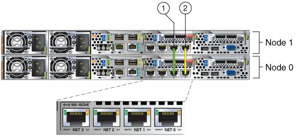
Description of "Figure 3-3 Interconnects When Using Fiber Connections to the Public Network on Oracle Database Appliance X4-2 and Oracle Database Appliance X5-2"
Oracle Database Appliance models X3-2, X4-2, and X5-2 can be shipped with one or two storage shelves. You can obtain the second shelf at a later time to double your storage capacity. Use the instructions in the section Attaching Storage Expansion Shelf if your Oracle Database Appliance has a storage expansion shelf, either during initial installation or if obtained later.
Attaching Storage Expansion Shelf
If you originally deploy Oracle Database Appliance with only one storage shelf, then you might add storage expansion shelf at any time without having to shut down your databases or applications.
Tip:
Oracle recommends that you add a storage expansion shelf when you have relatively little activity on your databases. As soon as Oracle Database Appliance recognizes the new storage, ASM automatically rebalances the disk groups, which might degrade database performance until the operation completes.Whether your storage expansion shelf was part of your original shipment or was obtained after deployment of Oracle Database Appliance, complete the following two tasks to install and to cable the shelf:
Installing a Storage Expansion Shelf
To install a storage expansion shelf:
-
Physically locate the storage expansion shelf below your Oracle Database Appliance, if possible, or else close enough to connect the provided cables.
Note:
The storage expansion shelf normally sits at the bottom of Oracle Database Appliance, beneath the storage shelf. However, because racks should always be provisioned from the bottom up, that space might be unavailable. In these cases, to avoid re-rack mounting the entire system, position the storage expansion shelf above the server nodes or even in a different, but adjacent, rack. -
The extension storage shelf is installed in exactly the same manner as the original storage shelf. For information about installing optional components in the Oracle Database Appliance, see the section "Optional Component Installation" in Chapter 4 of Oracle Database Appliance Owner's Guide.
-
Install the supplied cables as described in "Cabling a Storage Expansion Shelf" or as shown on the Oracle Database Appliance Setup Poster.
Caution:
Incorrect connections can cause data loss when adding a storage expansion shelf to Oracle Database Appliance with existing databases. -
Attach the supplied power cords as explained in "Attaching Power Cords and Initializing Components".
Caution:
Do not turn on power to the expansion shelf until you have added the cables as described in "Cabling a Storage Expansion Shelf".
Note:
Oracle recommends that you do not remove a storage expansion shelf from Oracle Database Appliance, whether the shelf was installed during the initial setup or added later.Cabling a Storage Expansion Shelf
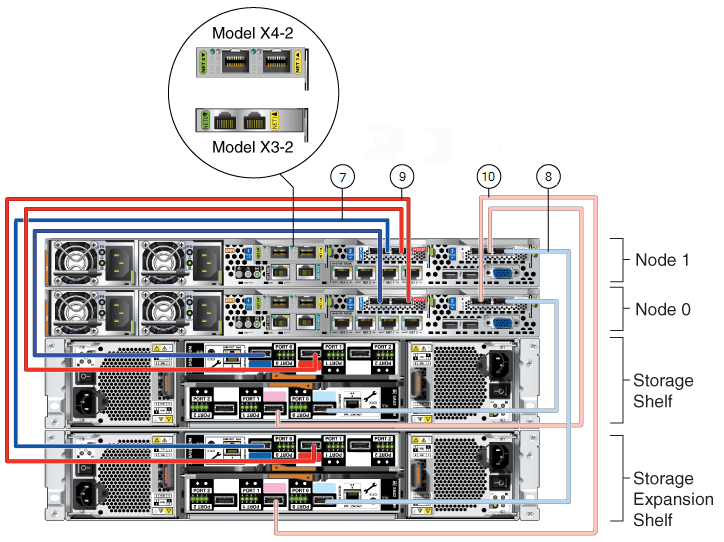
Figure 3-4 and Figure 3-5 show you how to insert the required cables into the storage expansion shelf of Oracle Database Appliance. The cables for the two nodes and the original storage shelf are included in the illustration for reference.
If you are able to distinguish colors, match the colors of the labels at the ends of each cable with the colored line shown in the following illustration. Also match the cable colors to the background colors of the socket identification labels.
If you are unable to use color coding, then use the callout numbers described in Table 3-2 to complete the cabling of the storage expansion shelf. Because all cables with the same terminations are interchangeable, you can ignore the color coding.
Figure 3-4 Cables for Storage Expansion Shelf on Oracle Database Appliance X5-2
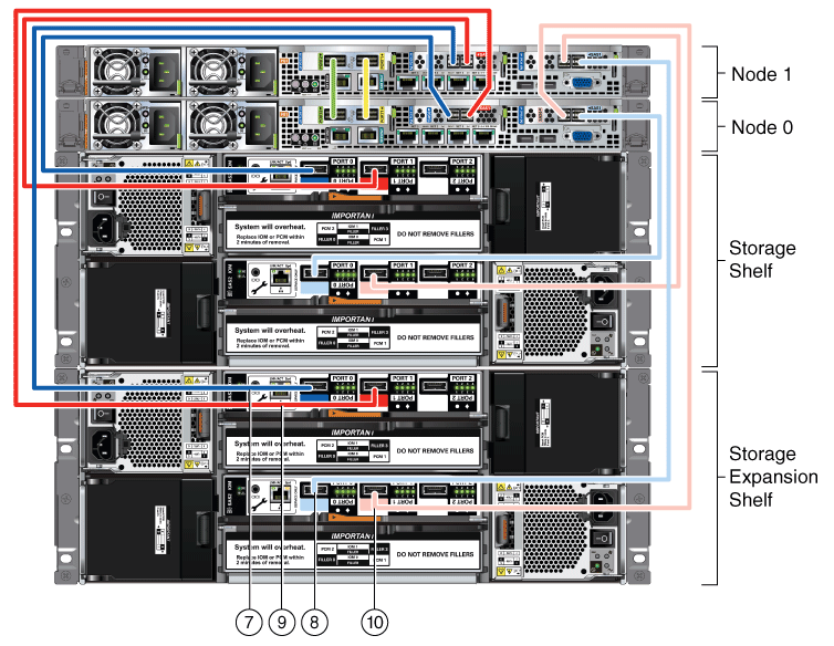
Description of "Figure 3-4 Cables for Storage Expansion Shelf on Oracle Database Appliance X5-2"
Figure 3-5 Cables for Storage Expansion Shelf on Oracle Database Appliance X3-2 and X4-2
Description of "Figure 3-5 Cables for Storage Expansion Shelf on Oracle Database Appliance X3-2 and X4-2"
The cables identified with callout numbers in Figure 3-4 and Figure 3-5 and described in Table 3-2 are included with each shipped Oracle Database Appliance storage expansion shelf. These cables are all black, but have colored labels at each end that match the references to cable colors in the text and the label colors on the back panels.
Note:
The back panel of each node contains three PCIe generation 3 terminal slots, with two sockets in each slot. The PCIe slots are labeled "X PCIe3," where "X" is the PCIe slot number. Table 3-2 identifies these slots as PCIe slot 1, PCIe slot 2, and PCIe slot 3, which matches the numbers on the labels reading from left to right. The storage expansion shelf back panel has two IO modules, one located above the other. Each IO module has three ports, numbered 0, 1, and 2. Table 3-2 identifies these ports as either "top" or "bottom" ports, for ports in the upper and in the lower IO module respectively.Table 3-2 Description of Callouts for Cabling Oracle Database Appliance Storage Expansion Shelf
| Callout Number from Figure 3-4 and Figure 3-5 | Description |
|---|---|
|
7 |
Dark blue SAS cable:
|
|
8 |
Light blue SAS cable:
|
|
9 |
Dark red SAS cable:
|
|
10 |
Light red SAS cable:
|
Caution:
Do not attach cables to ethernet ports in the I/O modules labeled "SERVICE ONLY" when cabling the system. These ports are intended for use by service engineers only.See Also:
Oracle Database Appliance Owner's Guide for details about cabling with the supplied Cable Management Arm.Attaching Peripheral Devices
Oracle Database Appliance is not equipped with devices for human interaction, such as a monitor or keyboard. To log in directly (not through a network), attach a monitor to the graphics card port and a keyboard and a mouse to the USB ports on Node 0 only. See callout 1 for the keyboard and mouse inputs and callout 2 for the monitor input in the following figures, where Figure 3-6 shows Oracle Database Appliance models X3-2 and X4-2. The Oracle Database Appliance X5-2 rear panel is slightly different however the peripheral device connections are the same as X3-2 and X4-2. Figure 3-7 shows Oracle Database Appliance Version 1.
Figure 3-6 Peripheral Device Connections for Oracle Database Appliance (Node 0)
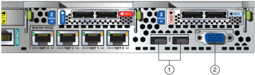
Description of "Figure 3-6 Peripheral Device Connections for Oracle Database Appliance (Node 0)"
Figure 3-7 Peripheral Device Connections for Oracle Database Appliance Version 1 (Node 0)
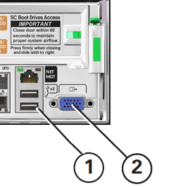
Description of "Figure 3-7 Peripheral Device Connections for Oracle Database Appliance Version 1 (Node 0)"
Booting Up the First Time
To ready Oracle Database Appliance for the powering on the first time, you need to attach all of the required power cords, which differ between models and options, and confirm that initialization completes successfully. You can then start up the system by switching on the process server nodes.
These two tasks are described in the following sections:
Attaching Power Cords and Initializing Components
Use the callouts in Figure 3-8 and Figure 3-9 and Table 3-3 as guides to insert the supplied power cords into Oracle Database Appliance models with external storage. Ensure that the electrical outlets providing the power are grounded before plugging in the power cords.
Figure 3-8 Power Cord Connections on Oracle Database Appliance X5-2
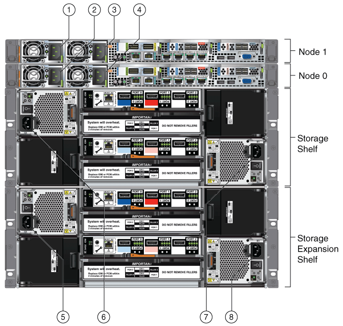
Description of "Figure 3-8 Power Cord Connections on Oracle Database Appliance X5-2"
Figure 3-9 Power Cord Connections on Oracle Database Appliance X4-2 and X3-2
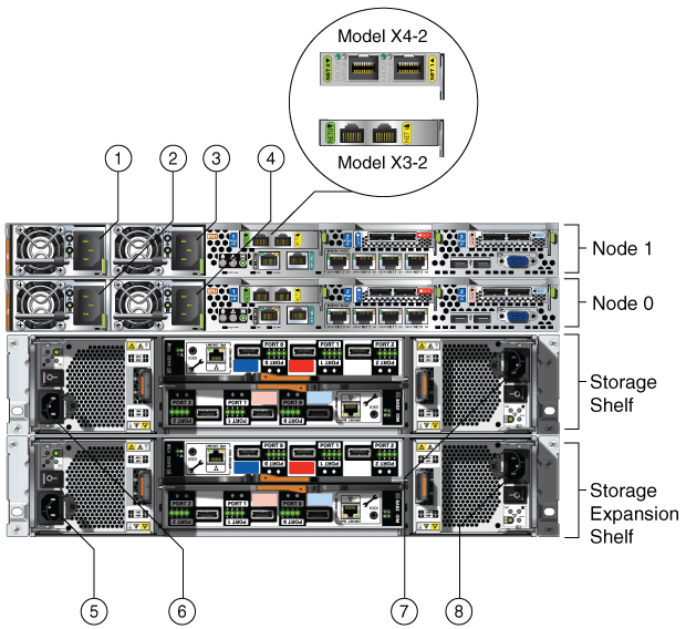
Description of "Figure 3-9 Power Cord Connections on Oracle Database Appliance X4-2 and X3-2"
If you only use a single AC circuit, connect both power cords for each component to that circuit. However, to maintain N+1 power supply redundancy, use two separate AC circuits. Then, for both nodes and the storage shelf or shelves, connect one power cord from each AC circuit into each component. See the following table, where the two separate AC circuits are denoted by AC1 and AC2, for the recommended power connections as identified by the callouts in the preceding figure.
Caution:
Before you insert any power cables, ensure that the power supply On/Off switch on the storage shelf is in the Off position. If a storage expansion shelf is installed, then ensure that the power supply switches on both storage shelves are in the Off position.Table 3-3 Electrical Power Cord Connections for Oracle Database Appliance with Storage Shelves
| Callout Number from Figure 3-8 and Figure 3-9 | Component | AC Circuit |
|---|---|---|
|
1 |
Node 1 |
AC1 |
|
2 |
Node 0 |
AC1 |
|
3 |
Node 1 |
AC2 |
|
4 |
Node 0 |
AC2 |
|
5 |
Storage expansion shelf (Not required for single storage shelf implementations) |
AC1 |
|
6 |
Storage shelf |
AC1 |
|
7 |
Storage shelf |
AC2 |
|
8 |
Storage expansion shelf (Not required for single storage shelf implementations) |
AC2 |
Oracle Database Appliance Version 1 hardware has only one power socket for each node. The power sockets are at the lower left corner of the rear panels. Ensure that the electrical outlets providing the power are grounded before plugging in the power cords.
See Also:
Oracle Database Owner's Guide for details about cabling with the supplied Cable Management Arm.Powering On the First Time
Before continuing with the following steps, ensure that all of the required power cables are attached to both Oracle Database Appliance nodes and to one or both storage shelves, if included in your system.
Note:
You might notice that the two nodes appear to be running as soon as you attach the power cords because the fans are turned on and the front panel LEDs start to blink or eventually remain on. However, to properly start the system processors, you must complete the steps in this section.-
If attached, switch the storage power supplies On/Off switch to the ”On” position for each storage shelf.
Each storage shelf has a two power switches, one located on the right side and one on the left side of the rear panel.
The disks begin to initialize which can take several minutes.
Note:
Do not apply main power to the server nodes until the storage shelves are fully initialized, indicated by the green LEDs on the shelves and the system processer (SP) on the nodes staying steadily lit. -
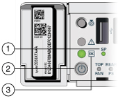
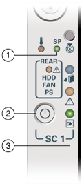
Wait for the server nodes, and storage shelves, if attached, to complete their initialization steps. To indicate that initialization is complete, the green system processer (SP) LEDs on the front of the nodes will stop blinking and remain steadily on. See callout 1 in the following figures, the first of which shows the front panel of Oracle Database Appliance Version 1 and second of which shows the front panel of all other models.
Figure 3-10 Front of Oracle Database Appliance Models X3-2, X4-2, and X5-2: Power Panel
Description of "Figure 3-10 Front of Oracle Database Appliance Models X3-2, X4-2, and X5-2: Power Panel"
Figure 3-11 Front of Oracle Database Appliance Version 1: Power Panel
Description of "Figure 3-11 Front of Oracle Database Appliance Version 1: Power Panel"
-
When both nodes are initialized, on each node:
-
Push the recessed Power button on the node's front panel (see callout 2 in the preceding figures).
-
Wait for several minutes until for the green Power OK LED on the node's front panel (see callout 3 in the preceding figures) to stay on instead of blinking.
Note:
Do not repeatedly push the power button, callout 2 in the preceding figures. -
Oracle Database Appliance is ready for use as soon as the green Power OK LEDs (see callout 3 in Figure 3-10) on the front of both system nodes remain steadily on.
-
Defining Your Public Network Option
After you power on Oracle Database Appliance X4-2 for the first time, a short script runs on each node. Use an attached keyboard to answer questions that the script displays on the local monitor.
Note:
The above statement is valid for Oracle Database Appliance X4-2 only. When you power on Oracle Database Appliance X5-2 for the first time, the system automatically defines your public network interface based on the interconnect. On Oracle Database Appliance X5-2, the InfiniBand network is used for the interconnect if InfiniBand cards are used. If InfiniBand cards are replaced with 10GbE SFP+ (fiber) cards, then the onboard 10GBase-T (Copper) ports are used for the interconnect. See Figure 3-3 for interconnect cabling instructions when InfiniBand cards are replaced with 10GbE SFP+ (fiber) cards.First, define your system's public connection type by responding to the following:
Do you want to use Fiber or Copper card for public network? Please Choose [C]opper or [F]iber.
If you are connecting to a copper-based public network, then enter C. If you are connecting to a fiber-based public network, then enter F. The script then prompts you to confirm your choice.
If you make a mistake or need to change your public network choice later, reconfigure your system by running the script /opt/oracle/oak/lib/setupX4network.pl as the root user on both nodes.
WARNING:
If you have already deployed the End-User Bundle (for a Bare Metal installation) or the ODA_BASE template (for a Virtualized Platform installation), then you will need to redeploy that software after running the setupX4network.pl procedure.
Configuring Oracle Integrated Lights Out Manager
Configure Oracle Integrated Lights Out Manager (Oracle ILOM) to manage Oracle Database Appliance independently of the operating system.
Although not required, Oracle ILOM provides alternate ways to restart and troubleshoot Oracle Database Appliance.
To configure Oracle ILOM, you will need:
-
a name and IP address for each of the two nodes
-
a password to replace the default Oracle ILOM password
-
access to a management network through an assigned netmask
-
an Ethernet cable connected from each node of Oracle Database Appliance, using the nodes' NET MGT ports, into the management network
In the default configuration, Dynamic Host Configuration Protocol (DHCP) is enabled in Oracle ILOM and the DHCP server automatically assigns network settings to each node. To determine the IP address or host name assigned by the DHCP server to the nodes, use the network tools provided with the DHCP server.
If you do not use DHCP, then use the custom option in Oracle Database Appliance Manager configurator to assign IP addresses and host names to Oracle ILOM when you deploy your database.
Note:
Until you complete Oracle Database Appliance configuration, as described in Chapter 4, you will not be able to access Oracle ILOM unless DCHP is enabled.See Also:
Chapter 2, "Overview of Oracle Database Appliance" in Oracle Database Appliance Owner's Guide for details about the port used for ILOM on your platformTo connect to the Oracle ILOM, use one of the following two methods:
-
Log in using a web interface by completing these steps:
-
Log in using a command line interface (CLI) by completing these steps:
-
-
Using a client system, establish a secure shell (SSH) connection by entering the following on the command line:
ssh -l rootsp_ip_addresswhere
sp_ip_addressis the IP address assigned by DHCP. -
Enter the default user name,
root, and the default password,changeme.The Oracle ILOM CLI prompt appears.
-
See Also:
The Oracle Integrated Lights Out Manager Documentation Library athttp://docs.oracle.com/cd/E19860-01/index.html for additional information about Oracle ILOM.Configuring Initial Network Connection
To manage your Oracle Database Appliance deployment across a network, you need to configure an initial network connection. You use this network to transfer deployment software to Oracle Database Appliance.
If you have physical access to your Oracle Database Appliance, then you can download deployment software to USB storage that you plug into the system, in which case you do not need an initial network.
Note:
An initial network configuration will be replaced during the final image deployment.-
Log in as
root, passwordwelcome1. If you are configuring the network on Oracle Database Appliance Virtualized Platform, then login to Dom0 to complete this step. -
Oracle recommends that you perform a validity check of cabling before you perform any other actions on Oracle Database Appliance with one or more storage shelves, unless you are planning a virtualized platform deployment. (For Virtualized Platform installations, the check is performed after deploying the system as described in Chapter 4). Perform this check by running the
oakcli validate -c storageTopologycommand. -
Run the command
oakcli configure firstnetto configure the initial network.You might need to refer to data that you collected on the work sheets in the first section of this chapter for some of the required values. Use the global option by accepting the default value in the first prompt and then provide the required data for the remaining prompts. You do not need to enter anything to accept the default values that are shown in square brackets at the end of prompts.
The following is an example shows the key features of the dialog, some details may be different depending on the model of Oracle Database Appliance. In this example, default values are always selected and values that you need to provide when running the command shown in italic font.
oakcli configure firstnet
Configure the network for the node(s)(local, global) [global]:
The network configuration for both nodes:
Domain Name:  your organization domain name
DNS Server(s):  Primary Dns Server:  your primary DNS server
                Secondary Dns Server:  your secondary DNS server
                Tertiary Dns Server:  your tertiary DNS server
Node Name       Host Name
0               your Node 0 host name
1               your Node 1 host name
Choose the network interface to configure (net1, net2, net3, net4) [net1]:
Configure DHCP on net1 (yes/no) [no]:
You have chosen static configuration on net1
Enter the IP address for net1 on Node 0: your Node 0 IP address
Enter the IP address for net1 on Node 1: your Node 1 IP address
Netmask for net1: your netmask
Gateway Address for net1 [<Gateway IP>]:
Plumbing the IPs now on Node 0 …
::::::::::::::::::::::::::::::::::::::::::::::::::
Plumbing the IPs now on Node 1 …
::::::::::::::::::::::::::::::::::::::::::::::::::
In the preceding example, the prompt for the net1 gateway address includes a default value, shown as <Gateway IP>. The program derives this gateway address using values from previous entries. You should accept this value unless your network administrator has provided a specific address that differs from the derived address.
Validating Oracle Appliance Manager Software Version
Before deploying Oracle Database Appliance, as described in Chapter 4, you should have the current version of the Oracle Appliance Manager software installed. Run the following command to find the installed version:
oakcli show version
Confirm that you have the version 12.1.2.3.0. If you have an earlier version, then see the My Oracle Support Note 888888.1 (at https://support.oracle.com/CSP/main/article?cmd=show&type=NOT&id=888888.1) for information on how to re-image your system with the current version.