Linux provides a firewall that runs on the appliance to prevent unauthorized access. This firewall enables various services on specific ports (for example, the default SSH port is 22). For more information on the default open ports, see Default ports.
Depending on your requirements, you might need to open up other ports on the firewall. This topic explains how to do this using IP tables on the Linux Firewall page of the Web Administration Interface (WAI). It shows example use cases that enable access to the necessary ports on the appliance by adding new rules to the Packet filtering IP table.
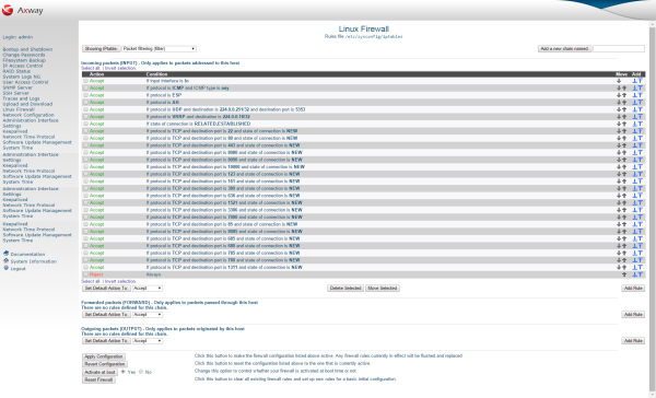
To restrict the types of connections and packets that your firewall will accept or forward, you need to create additional firewall rules. The best place for these rules is the Packet filtering IP table in the default Incoming packets (INPUT) rule chain.
The rules in a chain are evaluated in order from top to bottom, and the action taken is determined by whichever one matches first. If none match, the chain's default action is taken, which is usually to accept the packet. You can use this evaluation order to create a rule that allows a single IP address, followed by a rule to deny an entire network. The final effect is that every host in the network is denied except one. Because the ordering of rules is important, you might sometimes want to add a rule in the middle of an existing chain. To do this, click one of the arrow buttons under a chain's Add column to create a new rule before or after an existing rule.
The most common firewall actions are described as follows:
| Firewall action | Description |
|---|---|
| Do nothing | If a rule with this action is matched, nothing is done and processing continues to the next rule. |
| Accept | Matching packets are immediately accepted, and no further processing is performed in the chain. However, rules in other tables might still affect the packet. |
| Drop | Matching packets are silently discarded, as though they were never received at all. No further processing takes place in this chain or any other. |
| Userspace | Packets are passed to a normal userspace process. This action is rarely used. |
| Exit chain | Jump immediately to the end of the chain, and execute its default action instead. If this is used in a user-defined chain, processing returns to the rule that called it. |
| Run chain | Passes the packet on to the user-defined chain or custom target entered in the field next to it. For example, some of the available targets are as follows:
|
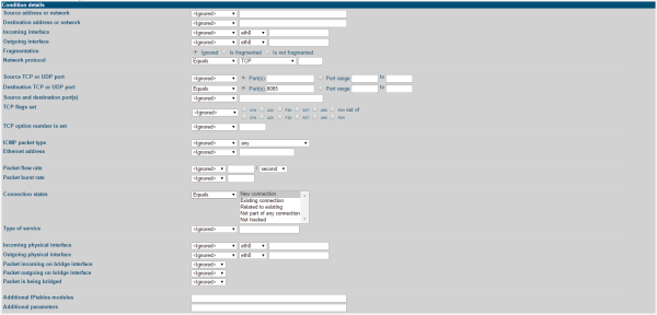
For each condition, you can select the following options:
| Condition | Description |
|---|---|
Ignored
|
The condition is not used at all when checking if a packet matches the rule. |
Equals
|
The packet must match the condition for it to match the entire rule. |
Does not equal
|
The packet must not match the condition for the rule to be executed. For example, if the Incoming interface
condition is set to Does not equal, and eth0
is selected, the rule would match only packets coming in on any interface except the primary Ethernet card. |
| Note | Because almost all network protocols involve traffic flowing in two directions, attempting to block only incoming traffic from some address using the Source address or network
condition also blocks connections to the address, because reply packets that are part of the connection are dropped. The same applies to blocking incoming data on a particular port using the Destination TCP or UDP port
condition. If in the unlikely case, the randomly chosen source port of a connection from your system matches the blocked port, any replies to it are dropped. For this reason, it is usually good practice when creating deny rules to set the Connection state
condition to Does not equal, and select Existing connection. This causes IP tables to keep track of outgoing connections made by your server, and not block them. |
As you can see, there are many different conditions available, which can be combined to create quite complex rules. Because there are so many conditions, you can also create new rules that are almost identical to existing rules. To do this, click an existing rule action in the table to edit it, and click the Clone rule button at the bottom of the page to display the rule creation form with all conditions and actions set based on the original rule. For more details, see Edit firewall rules.
You can use the Linux Firewall page in the WAI to edit any existing firewall rules created manually, in another program, or using this page. Even though the WAI does not support all of the available IP tables condition and action options, you can still use it to safely edit rules containing unknown options. However, only those known to the WAI can be changed, while others are left unchanged.
To edit a firewall rule, perform the following steps:
Packet filtering (filter)
table.You can move rules up and down in their chain using the arrows under the Move column on the main page. Because rules are evaluated in order by the firewall, changing their ordering can affect which traffic is allowed or denied. Whenever you create a new rule, it is added to the end of its chain, so it might be necessary to move it up the correct position to get the desired effect.
This example shows how to add a rule to the Incoming packets (INPUT)
table to open a new HTTP port 8085
to accept incoming traffic on the appliance. To open a different port, replace 8085
in the following steps:
HTTP port 8085.

8085
port without restrictions, so most of these options can use the default settings.
Equals
and TCP
.Equals
and Port(s). Enter 8085
in the text box.Equals
and New connection(NEW).In this example, the API Gateway has been configured to allow remote Java Management eXtensions (JMX) monitoring on port 8887. Although the port for the JMX connection is specified as 8887, this is for the Java Remote Method Invocation (RMI) registry only (and is specified when connecting with JConsole). Another, random, port is opened by JMX to export JMX RMI connection objects. There is no way to know in advance which port is used, and therefore which port to open on the firewall.
The easiest way to provide access through the firewall is to add a rule to the Incoming packets (INPUT)
table to allow access to any port from a particular IP address (the address of your client), or an IP address range (for example, the subnet of your client). In this example, the client IP address is 192.168.0.100.
Perform the following steps:
Allow connections from 192.168.0.100 for JMX.192.168.0.100
to connect without restrictions, so most of these options can use the default settings.Equals
, and enter the IP address in the text box. In this example, only 192.168.0.100
is allowed access. However, you could allow access to any address in the 192.168.0.0-255
range by entering 192.168.0.0/24.Distributed caching on the API Gateway uses RMI to transfer the data between each node in the distributed cache. RMI has a fixed listener port that can be opened easily, but unfortunately for the configuration of the firewall, it also sets up random ports for further communication and data transfer between nodes. This leads to a similar solution as for the JMX example where packets from a specified IP address or address range are accepted through the firewall. For automatic peer discovery, it would likely be best to use an IP address range or subnet. In this example, the 192.168.0.0 255.255.255.0
subnet is allowed access to any port on the appliance.
Perform the following steps:
Allow connections from 192.168.0.0/24 for distributed caching.192.168.0.0/24
subnet to connect without restrictions, so most of these options can use the default settings.Equals
and enter the IP addresses in the text box. In this example, enter 192.168.0.0/24.Communication with a CA SiteMinder Policy Server also involves connection to random ports on the appliance. This leads to a similar solution as for the JMX example where packets from a specified IP address or address range are accepted through the firewall. In this example, the IP address of the SiteMinder Policy Server is 192.168.0.100
. This IP address is allowed access to any port on the appliance.
Perform the following steps:
Allow connections from 192.168.0.100 for SiteMinder PS.192.168.0.100
to connect without restrictions, so most of these options can use the default settings.Equals
and enter the IP addresses in the text box. In this example, enter 192.168.0.100.Communication with a Remote Authentication Dial In User Service (RADIUS) server also involves connection to random ports on the appliance. This leads to a similar solution as for the JMX example where packets from a specified IP address or address range are accepted through the firewall. In this example, the IP address of the RADIUS Server is 192.168.0.100
. This IP address is allowed access to any port on the appliance.
Perform the following steps:
Allow connections from 192.168.0.100 for Radius.192.168.0.100
to connect without restrictions, so most of these options can use the default settings.Equals
and the IP addresses in the text box. In this example, enter 192.168.0.100.