Before sliding a power cooling into the Drive Enclosure, ensure that the power cooling module is oriented correctly. To ensure correct orientation, align the latch on the power cooling module with the inner area of the Drive Enclosure.
Caution
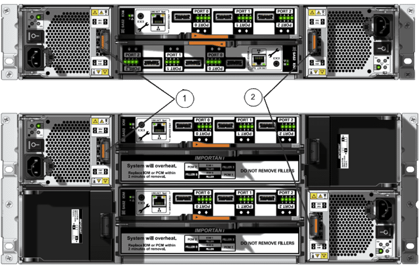
Inserting a power cooling module that is not oriented correctly into a Drive Enclosure can damage the power cooling module and the Drive Enclosure.Figure 1: Power cooling module orientation
- Legend
1 Latch on the left power cooling module 2 Latch on the right power cooling module
- With the attachment lever fully open, orient the power cooling module so that the latch aligns with the inner area of the Drive Enclosure and slide the power cooling module into the chassis slot.
Figure 2: Power cooling module with a fully open attachment lever
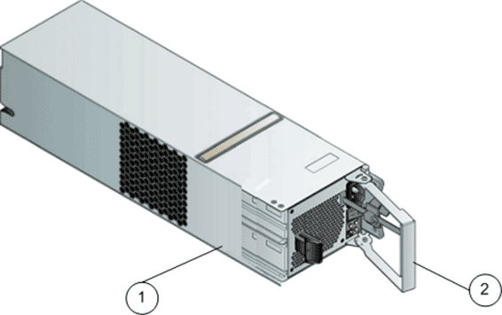
- Legend
1 Power cooling module 2 Opened attachment lever
- As the power cooling module contacts the Drive Enclosure chassis midplane, close the attachment lever.To confirm that the power cooling module is properly closed, listen for an audible click or feel the part engage with the Drive Enclosure chassis midplane.
Figure 3: Power cooling module (right side)
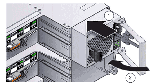
- Legend
1 Slide replacement power cooling module into Drive Enclosure chassis slot 2 Close the attachment lever
- Make sure that the power switch is off for the power cooling module.
- Plug the power cord into the power cooling module.
- Attach the power cord tie strap to the power cord.
- Power on the replacement power cooling module. When the power-on process completes, the following indicators should be present:
The Power status LED emits a steady green light.
All other LEDs are off.