- Unpack the component from its shipping carton.Note: Place the component on an antistatic mat if it must be set aside for any reason.
- Insert the SAS HBA that was placed aside and insert it in the lower PCIe slot as before within the replacement riser.Note: This step applies only to the HBA replacement procedure, when the HBA must be taken out of the riser and the SAS cable bundle must be disconnected.
- Reconnect the SAS cable bundle into the HBA inside the riser, if you had disconnected it.Note: This step applies only to the HBA replacement procedure, when the HBA must be taken out of the riser and the SAS cable bundle must be disconnected.
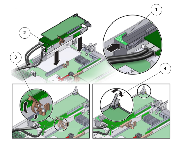
- Insert the riser into the PCIe slot on the Pilot motherboard and secure the riser in position using the three locking mechanisms.
Figure 1: Pilot riser insertion

- Legend
1 Slide card retainer 2 Riser 3 PCIe riser lever 4 Retention clip that secures the riser faceplate
Note: The three locking mechanisms that secure the riser in position on the Pilot motherboard include:Slide card retainer that secures the riser to the Pilot.
Retention clip that secures the riser faceplate.
PCIe riser lever that secures the riser to the PCIe slot on the Pilot motherboard.
Note: If you had removed the fan module (FM-0), replace the fan module back in the fan compartment.Note: Ensure that the rear bracket on the internal SAS HBA card in PCIe slot 4 is connected to the slot in the Pilot chassis side wall. If the bracket is not connected, remove the riser and reposition it so that the rear bracket connects to the side wall, and then gently press the riser into the motherboard connector. - Insert the filler panels, if any, inside the riser.