2 About the Cartridge Components
This chapter provides information about the components of the Oracle Communications Network Integrity Optical Circuit Assimilation cartridge.
The Optical Circuit Assimilation cartridge contains the following actions:
Assimilate Optical Circuits
The Assimilate Optical Circuits action reads unprocessed circuit data, such as topological links, cross-connects, and other partially assimilated circuit data, from previous scans and builds end-to-end circuits.
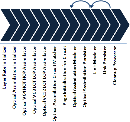
The Assimilate Optical Circuits action contains the following processors run in the following order:
Figure 2-1 illustrates the processor workflow of the Assimilate Optical Circuits action.
Figure 2-1 Assimilate Optical Circuits Processor Workflow

Description of ''Figure 2-1 Assimilate Optical Circuits Processor Workflow''
Layer Rate Initializer
This processor initializes the layer rates for cross-connects and topological links.
You can extend the assimilation action with a processor that overrides the default layer rates and proposes new ones.
Optical Assimilation Initializer
This processor is used to set up the data for the Intermediate Assimilation Model, in preparation for the assimilation processors, by doing the following:
-
If the Process Discovery Results field in the UI is set to true (which indicates that this is the first level of assimilation in a series of hierarchical assimilation scans), this processor places the discovered topological link and cross-connect data in the Intermediate Assimilation Model.
-
Initializes the scope of the scan by labeling the defined scan data from other actions and in the Intermediate Assimilation Model with the scan ID from the current assimilation action.
Optical VC4 HOT HOP Assimilator
This processor takes the data from the Intermediate Assimilation Model and traces all higher order transport and customer circuits that are at the rate of VC4.
Optical VC3 LOT LOP Assimilator
This processor takes the data from the Intermediate Assimilation Model and traces all lower order transport and customer circuits that are at the rate of low order VC3.
Optical VC12 LOT LOP Assimilator
This processor takes the data from the Intermediate Assimilation Model and traces all lower order transport and customer circuits that are at the rate of VC12.
Optical Assimilation Circuit Matcher
This processor matches assimilated data with your inventory system. Cross-connect and topological link object naming can often vary over a network. When this processor matches an assimilated circuit with an inventory circuit, it applies the inventory circuit name to the assimilated circuit, thus reducing the number of detected discrepancies from the inventory system to ensure that the assimilated data matches the inventory data as closely as possible, to reduce the quantity of detected discrepancies.
The default circuit matching logic can query Import action scan results. You can extend the Assimilate Optical Circuits action to retrieve circuit naming information from another source or to change the criteria for circuit matching.
The default circuit matching logic matches circuits by doing all of the following:
-
Searches for a circuit with the same A-port and Z-port, then searching for matching circuit and path names.
If this processor finds a matching circuit in the inventory scan results, it assigns the inventory circuit name to the network circuit. Otherwise, this processor generates a name for the circuit and its paths.
-
Returns the name of the result group (by default, the device name) into which to save the matched circuit.
This adds some flexibility where the grouping is determined by the import results.
-
Ensures that discrepancy detection functions properly.
The circuit matcher determines whether the network path and the inventory path are in the same order. If the orders are reversed, this processor reverses the assimilated circuit (even circuits with multiple paths and protected paths) to match the inventory circuit.
-
Determines if a circuit is rerouted.
The processor compares the paths between the network and inventory circuits to see if parent pipes are different at any point. This processor adds a flag to the results of a rerouted circuit.
-
Merges partial duplicate circuits.
After the processor has finished circuit matching, the processor takes partial circuits with the same circuit name and merges them together and redefines their start and end port. The processor attempts to match the updated circuit with a circuit from the inventory.
If the Model Incomplete Circuits field in the UI is set to True, this processor searches for complete circuit names and partial circuit names. If Model Incomplete Circuits is set to False, this processor searches for complete circuit names only.
Page Initialization for Circuit
This processor counts the number of circuits and synchronous transport modules (STMs). It initializes the number of pages to be processed based on the page size. This processor passes the pages for STMs to the Link Modeler processor and passes the pages for circuits to the Optical Assimilation Modeler processor.
Optical Assimilation Modeler
This processor takes each circuit from the Intermediate Assimilation Model and models it in the circuit hierarchy. The result for each unmatched circuit appears under one of the two end-device result groups. Matched circuit are modeled under the result group provided by the Optical Assimilation Circuit Matcher processor.
If the Model Incomplete Circuits field in the UI is set to True, this processor also models all partial circuits.
Optical Assimilation Persister
This processor saves the modeled circuit data to the Network Integrity database.
Link Modeler
This processor models STMs in the Intermediate Assimilation Model. Matched STMs are modeled under a result group provided by the Optical Assimilation Circuit Matcher processor. Unmatched STMs appear under one of the two end-device result groups.
Link Persister
This processor saves the modeled link data to the Network Integrity database.
Cleanup Processor
This processor flushes the Intermediate Assimilation Model when the Is Top Level Assimilation list in the UI is set to True.
Abstract Optical Circuit Discrepancy Detection
The Abstract Optical Circuit Discrepancy Detection action is used to build a solution that detects discrepancies between assimilated data and data imported from an inventory system.
See Network Integrity Developer's Guide for more information about discrepancy detection.
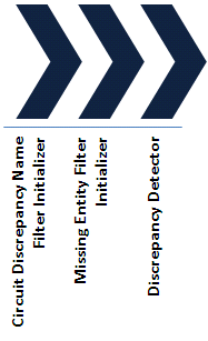
The Abstract Optical Discrepancy Detection action is made up of the following processors run in the following order:
Figure 2-2 illustrates the processor workflow of the Abstract Optical Circuit Discrepancy Detection action for the Optical Circuit Assimilation cartridge.
Figure 2-2 Abstract Optical Discrepancy Detection Action Processor Workflow

Description of ''Figure 2-2 Abstract Optical Discrepancy Detection Action Processor Workflow''
Circuit Discrepancy Name Filter Initializer
This processor implements discrepancy filters to populate the Custom attribute of discrepancies related to the same circuit. In this context, circuit can mean Topological Link, Transport Pipe, or Circuit.
This processor retrieves the circuit name from the Custom attribute and uses it to relate any discrepancies on a circuit or its parts (such as pipe termination point, trail path, or trail pipe). In Network Integrity, you can search on the circuit name to find all discrepancies related to a particular circuit.
Missing Entity Filter Initializer
During hierarchical assimilation, there is not enough information available in any one assimilation scan to properly detect missing circuit discrepancies.
The Optical Model uses InventoryGroup containers (such as Links, Transport, or Circuits) to organize circuits. The Assimilate Optical Circuits action can be done hierarchically, meaning that not all circuits are known until the topmost assimilation scan completes.
By default, discrepancy detection generates missing entity discrepancies for circuits that are not traced until later scans. This processor applies a filter to such circuits to avoid false discrepancies. The Discrepancy Detection action must be extended to correctly identify authentic discrepancies in hierarchical assimilation.
This processor returns True if the assimilation scan is neither first nor last in a hierarchical assimilation scan. The filter is not applied for a simple assimilation scan.
You can extend the Discrepancy Detection action to apply different conditions. If an extending action uses a different condition, disabling the filter (which would allow for false discrepancies) during the last hierarchical assimilation, the assimilation action should also be extended. Any circuits present in input scans should be copied to this scan as a temporary entity (called a shadow entity). Only the name and type need to be populated, along with setting the shadow attribute to True. For more information on shadow entities, see Network Integrity Developer's Guide. If information is available about whether the circuit was matched in inventory, then circuits known to not exist in inventory do not need to be copied.
Discrepancy Detector
This processor inherits base operations from the base detection cartridge. See Network Integrity Developer's Guide for more information about the Base Detection Cartridge.