5 About Cartridge Modeling
This chapter explains how the Oracle Communications Network Integrity Optical Circuit Assimilation cartridge models collected data.
About Cartridge Modeling
The Assimilate Optical Circuits action models its results to the Optical Model for Network Integrity. For more information on the Optical Model for Network Integrity, see Network Integrity Developer's Guide.
This cartridge models its results as the following entities:
-
Topological Links
-
Transport Circuits
-
Customer Circuits
Both the Optical Circuit Assimilation cartridge and the Optical Model for Network Integrity support fully-protected and partially-protected circuits. Circuit protection is known as subnetwork connection protection (SNCP).
The Optical Circuit Assimilation cartridge uses an intermediate or staging model to manipulate the assimilated data before persisting the fully-modeled circuits to the Optical Model. See "About the Intermediate Assimilation Model" for more information.
About Fully-Protected Circuits
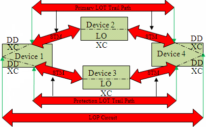
A fully-protected circuit is one with a fully redundant path between the A-port and the Z-port: two paths leave the A-port and do not converge until the Z-port. See Figure 5-3, "Fully-Protected LOP", for an example of a fully-protected circuit.
About Partially-Protected Circuits
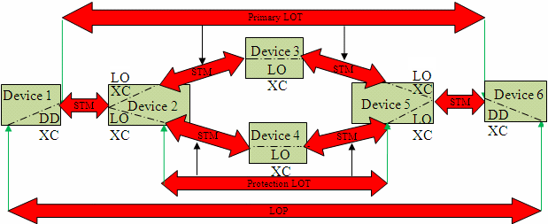
A partially-protected circuit is one with redundant segments, but not fully redundant. For example, a circuit that starts off unprotected, but then enters one or more optical rings, providing protection for one or more segments of the circuit. See Figure 5-4, "Partially-Protected LOP", and Figure 5-5, "Partially-Protected LOP with Multiple Protection Segments", for examples of partially-protected circuits.
About Circular Circuits
A circular circuit (or a loop circuit) is one with a duplicate trail pipe in the path. The Optical Circuit Assimilation cartridge models a circular circuit as a partially-protected circuit with a discrepancy. The discrepancy status is set to Ignore, because the circuit has to be fixed in the network.
You can identify circular circuits by reviewing the trail path information of the circuit with the discrepancy set to Ignore and finding a duplicate trail pipe. Or you can view the diagnostic logs for instances of "circular," as shown in the following example:
Found circular VC12 path in A direction at port port_number.
Found circular VC12 path in Z direction at port port_number.
About SDH JKLM Values
JKLM values are used to define the path and indexes a channel uses within the synchronous digital hierarchy:
-
J is the AUG index (1..n)
-
K is the TUG-3 index (1..3)
-
L is the TUG-2 index (1..7)
-
M is the TU-12 index (1..3)
The following list represents SDH JKLM channel index mappings:
-
J(AUG)=VC4 139.264(E4)
-
K(TUG-3)=VC3 34.368(E3)
-
L(TUG-2)=None
-
M(TU-12)=VC12 2.048(E1)
An example JKLM value for an SDH connection termination point (CTP) VC-12 on an STM-16 is /sts3c_au4-j=5/vt2_tu12-k=1-l=5-m=2.
Higher order transports (HOTs) and paths (HOPs) can ride on VC4(AUG) pipes. Lower order paths (LOPs) can ride on VC3(AUG/TUG-3) pipes and on VC12(AUG/TUG-3/TUG-2/TU-12) pipes.
All pipes have either a J, JK, or JKLM value in the hierarchy. The Optical Circuit Assimilation cartridge models all pipes with full JKLM values, with a value of 0 for any unused indexes. A VC4 pipe with just a J value sets KLM index values to 0 (for example: 3000). A VC3 pipe with just a JK value sets the LM index values to 0 (for example: 3200).
Table 5-1 shows the layer rates for different types of cross-connects.
About the Intermediate Assimilation Model
Before persisting fully modeled circuits and paths to the Optical Model, the assimilated data is staged in the Intermediate Assimilation Model. Staging the data in the Intermediate Assimilation Model reduces system traffic and improves performance.
The Intermediate Assimilation Model also provides a safe buffer in the event that a scan fails or is interrupted by not manipulating live data in the database. The Cleanup processor flushes the Intermediate Assimilation Model at the end of a scan run or series of hierarchical scans. Failures and errors are flushed when the Cleanup processor runs.
When hierarchical information is being assimilated, the Intermediate Assimilation Model passes the data onto follow-on assimilation actions.
Figure 5-1 shows the relationships for an unprotected LOP. There are relationships between the LOP, LOT, HOT, and STMs. The LOT can reference both an HOT and an STM as the parent. The LOP has only one path.
Figure 5-2 shows the relationships for an unprotected HOP. This HOP has only one path.
Figure 5-3 shows a circuit with multiple paths. One path is the primary path and the other is the protected path. This is an example of a fully-protected circuit where the LOP has two LOT paths.
Figure 5-4 shows a partially-protected circuit. The protection path only represents the protected segments of the LOP. The protection path is protecting only part of the circuit, between device 2 and device 5, by taking a different path through device 4. The segments between device 1 and 2 and between device 5 and 6 are not protected.
Figure 5-5 shows a more complex example of a partially-protected LOP, containing multiple protected segments.
Assimilation Data Modeling
By default, when the Optical Circuit Assimilation cartridge models assimilated data, it begins by modeling the physical tree, followed by the logical tree. When you extend a cartridge or create a custom cartridge, ensure that the assimilated data is modeled in this order.
The following tables explain what information is used to assimilate circuit entities.
Table 5-2 lists the cross-connect information used in the assimilation of circuits.
Table 5-2 Cross-Connect Assimilation Data
| Field | Description |
|---|---|
|
SCANRUNID(long) |
The scan run ID of the assimilation scan. |
|
DEVICE(string) |
The device name. |
|
APORT(string) |
The port name on the start-side of the cross-connect (A-port). |
|
ZPORT(string) |
The port name on the end-side of the cross-connect (Z-port). |
|
RATE(short) |
The layer rate code. |
|
ACHANNELHO(string) |
The J channel on the A-port of the cross-connect. |
|
ZCHANNELHO(string) |
The J channel on the Z-port of the cross-connect. |
|
ACHANNELLO(String) |
The KLM channel on the A-port of the cross-connect. |
|
ZCHANNELLO(String) |
The KLM channel on the Z-port of the cross-connect. |
|
PATHREF(long) |
An optional reference to the path. |
|
PROTSTATUS(String) |
The protection status: W for primary, P for backup. |
|
PROCESSED(Boolean) |
The circuit tracing status indicator (default is false). |
Table 5-3 lists the STM information used in the assimilation of circuits.
Table 5-3 STM Assimilation Data
| Field | Description |
|---|---|
|
SCANRUNID(long) |
The scan run ID of the assimilation scan. |
|
STMNAME(string) |
N/A |
|
RGROUP(string) |
Result group to which to persist the data. |
|
ADEVICE(string) |
The device name of the first device (A-device). |
|
ZDEVICE(string) |
The device name of the last device (Z-device). |
|
APORT(string) |
The port name on the start-side of the A-device (A-port). |
|
ZPORT(string) |
The port name on the end-side of the Z-device (Z-port). |
|
RATE(short) |
The layer rate code. |
Table 5-4 lists the path information used in the assimilation of circuits.
Table 5-4 Path Assimilation Data
| Field | Description |
|---|---|
|
SCANRUNID(long) |
The scan run ID of the assimilation scan. |
|
ADEVICE(string) |
The device name of the first device (A-device). |
|
ZDEVICE(string) |
The device name of the last device (Z-device). |
|
APORT(string) |
The port name on the start-side of the A-device (A-port). |
|
ZPORT(string) |
The port name on the end-side of the Z-device (Z-port). |
|
AFINAL(Boolean) |
Indicates whether the pipe is completely traced at the A-port (default is false). |
|
ZFINAL(Boolean) |
Indicates whether the pipe is completely traced at the Z-port (default is false). |
|
CIRCUITREF(long) |
An optional reference to an HOT, HOP, or LOP. |
|
RATE(short) |
The layer rate code. |
|
PROTSTATUS (string) |
The protection status: M for primary, P for protection path. |
|
ACHANNELHO(string) |
The J channel on the A-port of the path. |
|
ZCHANNELHO(string) |
The J channel on the Z-port of the path. |
|
ACHANNELLO(string) |
The KLM channel on the A-port of the path. |
|
ZCHANNELLO(string) |
The KLM channel on the Z-port of the path. |
|
REROUTED(Boolean) |
Indicates whether the same circuit followed a different path in inventory (default is false). |
|
PATHNAME(string) |
The path name. |
Table 5-5 lists the circuit information used in the assimilation of circuits.
Table 5-5 Circuit Assimilation Data
| Field | Description |
|---|---|
|
SCANRUNID(long) |
The scan run ID of the assimilation scan. |
|
CIRCUITNAME(string) |
The circuit name taken from the Inventory data. |
|
TYPE(string) |
Indicates whether the circuit is a transport circuit or customer circuit. |
|
RGROUP(string) |
Result group to which to persist the data. |
|
ADEVICE(string) |
The device name of the first device (A-device). |
|
ZDEVICE(string) |
The device name of the last device (Z-device). |
|
APORT(string) |
The port name on the start-side of the A-device (A-port). |
|
ZPORT(string) |
The port name on the end-side of the Z-device (Z-port). |
Table 5-6 lists the CPCRels information used in the assimilation of circuits.
Table 5-6 CPCRels Assimilation Data
| Field | Description |
|---|---|
|
SCANRUNID(long) |
The scan run ID of the assimilation scan. |
|
PARENTPIPE(long) |
A pointer to the parent pipe, such as a link for an HOT. |
|
CHILDPIPE(long) |
A pointer to the child pipe, such as the HOT using a link. |
|
CHANNEL(string) |
The JKLM channel of the child circuit within the parent. |
|
PARENTTYPE(String) |
The circuit type of the parent circuit, such as STM. |
|
SEQUENCE(LONG) |
The order of the parent circuit, such as 3,2,1,-1,-2,-3… |


