5 VSM 6 Physical Site Readiness Planning
This chapter provides information about activities designed to ensure the site is equipped to accommodate the power, safety, environmental, HVAC, and data handling requirements of VSM 6 system equipment. Key site readiness planning considerations include, but are not limited to:
-
Site surveys to evaluate and eliminate or mitigate factors which could negatively affect delivery, installation, and operation of VSM 6 system equipment
-
A plan for the layout and location of VSM 6 system equipment and cabling that allows for efficient use and easy maintenance, plus adequate space and facilities for Oracle support personnel and their equipment
-
Facilities construction that provides an optimum operating environment for VSM 6 system equipment and personnel, and safe flooring and protection from fire, flooding, contamination, and other potential hazards
-
Scheduling of key events and task completion dates for facilities upgrades, personnel training, and delivery, implementation, installation, testing, and certification activities
Customers ultimately are responsible for ensuring that their site is physically prepared to receive and operate VSM 6 system equipment, and that the site meets the minimum specifications for equipment operation as detailed in this guide.
The Site Readiness Planning Process
Site readiness planning activities, tasks, and participants include:
Key High-Level Activities
-
Select site readiness team members, and define roles and responsibilities
-
Complete site surveys to:
-
Document existing or potential external and internal environmental hazards.
-
Assess site power, safety, environmental, HVAC, and data handling capabilities versus VSM 6 system requirements.
-
Confirm floor load ratings along the transit path and at the installation location for VSM 6 VTSS cabinets.
-
Assess ceiling, hallway, and door clearances, elevator capacities, and ramp angles versus VSM 6 VTSS cabinet requirements.
-
-
Attend planning meetings.
Key Sub-Tasks
-
Verify site power, safety, environmental, HVAC, and data handling capabilities match VSM 6 VTSS requirements.
-
Define plan to eliminate/mitigate environmental hazards.
-
Evaluate floor load ratings along transit path and at the VSM 6 VTSS installation location.
-
Verify site door, hall and ceiling clearances, elevator capacity, and ramp angles match VSM 6 VTSS requirements.
-
Identify required infrastructure modifications/upgrades; set work completion schedule.
-
Evaluate readiness progress, and certify site readiness.
Site Evaluation – External Considerations
Several months before delivery of VSM 6 system equipment, a readiness planning team should identify and evaluate all external site factors that present existing or potential hazards, or which could adversely affect delivery, installation, or operation of the system. External factors that should be evaluated include:
-
Reliability and quality of electrical power provided by the local utility, backup power generators, and uninterruptible power supplies (UPSs)
-
Proximity of high-frequency electromagnetic radiation sources (for example, high-voltage power lines; television, radio, and radar transmitters)
-
Proximity of natural or man-made floodplains and the resultant potential for flooding in the data center
-
Potential effects of pollutants from nearby sources (for example, industrial plants)
If any existing or potential negative factors are discovered, the site readiness planning team should take appropriate steps to eliminate or mitigate those factors before VSM 6 system equipment is delivered. Oracle Global Services offers consultation services and other assistance to identify and resolve such issues. Contact your Oracle account representative for more information.
Site Evaluation – Internal Considerations
Several months before delivery of VSM 6 system equipment, a readiness planning team should identify and evaluate all internal site factors that present existing or potential hazards, or which could adversely affect delivery, installation, or operation of the system. Internal factors that should be evaluated include:
-
Structural dimensions, elevator capacities, floor-load ratings, ramp inclines, and other considerations when transferring equipment point-to-point between the delivery dock, staging area, and data center installation site
-
Site power system(s) design and capacity
-
VSM 6 system equipment power system design and capacity
-
Data center safety system design features and capabilities
-
Data center environmental (HVAC) design features and capabilities
-
Potential effects of corrosive materials, electrical interference, or excessive vibration from sources near to system equipment.
If any existing or potential negative factors are discovered, the site readiness planning team should take appropriate steps to eliminate or mitigate those factors before VSM 6 system equipment is delivered. Oracle Global Services offers consultation services and other assistance to identify and resolve such issues. Contact your Oracle account representative for more information.
Transferring Equipment Point-to-Point
Site conditions must be verified to ensure all VSM 6 system equipment can be safely transported between the delivery dock, staging area, and data center without encountering dimensional restrictions, obstructions, or safety hazards, or exceeding rated capacities of lifting and loading equipment, flooring, or other infrastructure. Conditions that must be verified are described below.
Structural Dimensions and Obstructions
Dimensions of elevators, doors, hallways, and so on must be sufficient to allow unimpeded transit of VSM 6 cabinets (in shipping containers, where appropriate) from the delivery dock to the data center installation location. See VSM 6 Overall Dimensions for VSM 6 cabinet-dimension details.
Elevator Lifting Capacities
Any elevators that will be used to transfer VSM 6 cabinets must have a certified load rating of at least 1050 kg (2312 lbs.). This provides adequate capacity to lift the heaviest fully-populated VSM 6 cabinet (roughly 751 kg (1652 lbs.) and a pallet jack (allow 100 kg/220 lbs.) and two persons (allow 200 kg/440 lbs.). See VSM 6 Weight for additional cabinet-weight details.
Floor-Load Ratings
Solid floors, raised floors, and ramps located along the transfer path for VSM 6 cabinets must be able to withstand concentrated and rolling loads generated by the weight of a populated cabinet, the pallet jack used to lift the cabinet, and personnel who are moving the cabinet from point to point.
Raised floor panels located along a transfer path must be able to resist a concentrated load of 751 kg (1652 lbs.) and a rolling load of 181 kg (400 lbs.) anywhere on the panel, with a maximum deflection of 2 mm (0.08 in.). Raised floor pedestals must be able to resist an axial load of 2268 kg (5000 lbs.). See Floor Loading Requirements for additional floor-loading details.
When being moved from one location to another, a VSM 6 cabinet generates roughly twice the floor load as in a static state. Using 19 mm (0.75 in.) plywood along a transfer path reduces the rolling load produced by a cabinet.
Data Center Safety
Safety must be a primary consideration in planning installation of VSM 6 system equipment, and is reflected in such choices as where equipment will be located, the rating and capability of electrical, HVAC, and fire-prevention systems that support the operating environment, and the level of personnel training. Requirements of local authorities and insurance carriers will drive decisions about what constitutes appropriate safety levels in a given environment.
Occupancy levels, property values, business interruption potential, and fire-protection system operating and maintenance costs should also be evaluated. The Standard for the Protection of Electronic Computer / Data Processing Equipment (NFPA 75), the National Electrical Code (NFPA 70), and local and national codes and regulations can be referenced to address these issues.
Emergency Power Control
The data center should be equipped with readily-accessible emergency power-off switches to allow immediate disconnection of electrical power from VSM 6 system equipment. One switch should be installed near each principal exit door so the power-off system can be quickly activated in an emergency. Consult local and national codes to determine requirements for power disconnection systems.
Fire Prevention
The following fire-prevention guidelines should be considered in the construction, maintenance, and use of a data center:
-
Store gases and other explosives away from the data center environment.
-
Ensure data center walls, floors, and ceilings are fireproof and waterproof.
-
Install smoke alarms and fire suppression systems as required by local or national codes, and perform all scheduled maintenance on the systems.
Note:
Halon 1301 is the extinguishing agent most commonly used for data center fire suppression systems. The agent is stored as a liquid and is discharged as a colorless, odorless, electrically nonconductive vapor. It can be safely discharged in occupied areas without harm to personnel. Additionally, it leaves no residue, and has not been found to cause damage to computer storage media. -
Install only shatterproof windows, in code-compliant walls and doors.
-
Install carbon dioxide fire extinguishers for electrical fires and pressurized water extinguishers for ordinary combustible materials.
-
Provide flame-suppressant trash containers, and train personnel to discard combustible waste only into approved containers.
-
Observe good housekeeping practices to prevent potential fire hazards.
Site Power Distribution Systems
A properly installed power distribution system is required to ensure safe operation of VSM 6 system equipment. Power should be supplied from feeders separate from those used for lighting, air conditioning, and other electrical systems.
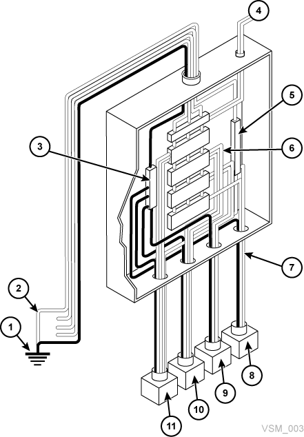
A typical input power configuration, shown in Figure 5-1, is either a five-wire high-voltage or a four-wire low-voltage type, with three-phase service coming from a service entrance or separately derived source, and with overcurrent protection and suitable grounding. A three-phase, five-wire distribution system provides the greatest configuration flexibility, since it allows power to be provided to both three-phase and single-phase equipment.
In Figure 5-1:
1 - Service entrance ground or suitable building ground
2 - Only valid at service entrance or separately derived system (transformer)
3 - Ground Terminal Bar (bound to enclosure) Same size as neutral
4 - Remotely Operated Power Service Disconnect
5 - Neutral Bus
6 - Circuit Breakers of Appropriate Size
7 - Branch Circuits
8 - 120V Single Phase
9 - 208/240V Single Phase
10 - 208/240V 3-Phase (4 wire)
11 - 208/240V 3-Phase (5 wire
Equipment Grounding
For safety and ESD protection, VSM 6 system equipment must be properly grounded. VSM 6 cabinet power cables contain an insulated green/yellow grounding wire that connects the VSM 6 frame to the ground terminal at the AC source power outlet. A similar insulated green or green/yellow wire ground, of at least the same diameter as the phase wire, is required between the branch circuit panel and the power receptacle that attaches to each cabinet.
Source Power Input
Voltage and frequency ranges at the AC source power receptacle(s) that will supply power to VSM 6 system equipment must be measured and verified to meet the following specifications:
-
Source Power: AC, single-phase, 3-wire
-
Voltage Range: 170-240
-
Frequency Range (Hz): 47-63
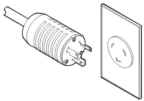
If you are installing the VSM 6 cabinet in the North and South America, Japan and Taiwan, ensure that the designated power sources are NEMA L6-30R receptacles, and ensure that the cabinet power cords are terminated with the required NEMA L6-30P plugs. The factory ships power cords with NEMA L6-30P plugs to North and South America, Japan and Taiwan. Shipments to EMEA and APAC will ship with IEC309 32A 3 PIN 250VAC IP44 plugs. Figure 5-2 shows a NEMA L6-30P plug and L6-30R receptacle.
If you are installing the VSM 6 cabinet outside of North and South America, Japan and Taiwan, ensure that designated source-power receptacles meet all applicable local and national electrical code requirements. Then attach the required connectors to the three-wire ends of the cabinet power cords.
Dual Independent Source Power Supplies
VSM 6 cabinets have a redundant power distribution architecture designed to prevent disruption of system operations from single-source power failures. Four 30 Amp power plugs are required. To ensure continuous operation, all power cables must be connected to separate, independent power sources that are unlikely to fail simultaneously (for example, one to local utility power, the others to an uninterruptible power supply (UPS) system). Connecting multiple power cables to the same power source will not enable this redundant power capability.
Transient Electrical Noise and Power Line Disturbances
Reliable AC source power free from interference or disturbance is required for optimum performance of VSM 6 system equipment. Most utility companies provide power that can properly operate system equipment. However, equipment errors or failures can be caused when outside (radiated or conducted) transient electrical noise signals are superimposed on power provided to equipment.
Additionally, while VSM 6 system equipment is designed to withstand most common types of power line disturbances with little or no effect on operations, extreme power disturbances such as lightning strikes can cause equipment power failures or errors if steps are not taken to mitigate such disturbances.
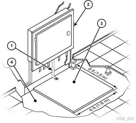
To mitigate the effects of outside electrical noise signals and power disturbances, data center source power panels should be equipped with a transient grounding plate similar to that shown in Figure 5-3.
In Figure 5-3:
1 - Flat Braided/Strained Wire
2 - Power Panel
3 - Plate
4 - Concrete Floor
Electrostatic Discharge
Electrostatic discharge (ESD) static electricity is caused by movement of people, furniture, and equipment. ESD can damage circuit card components, alter information on magnetic media, and cause other equipment problems. The following steps are recommended to minimize ESD potential in the data center:
-
Provide a conductive path from raised floors to ground.
-
Use floor panels with nonconducting cores.
-
Maintain humidity levels within recommended control parameters.
-
Use grounded anti-static work mats and wrist straps to work on equipment.
HVAC Requirements
Cooling and air-handling systems must have sufficient capacity to remove heat generated by equipment and data center personnel. Raised-floor areas should have positive underfloor air pressure to facilitate airflow. If conditions change within a data center (for example, when new equipment is added or existing equipment is rearranged), airflow checks should be done to verify sufficient airflow.
Environmental Requirements and Hazards
VSM 6 system components are sensitive to corrosion, vibration, and electrical interference in enclosed environments such as data centers. Because of this sensitivity, equipment should not be located near areas where hazardous or corrosive materials are manufactured, used, or stored, or in areas with above-average electrical interference or vibration levels.
For best performance, equipment should be operated at nominal environmental conditions. If VSM 6 system equipment must be located in or near adverse environments, additional environmental controls should be considered to mitigate those factors before installation of the equipment.
Floor Construction Requirements
VSM 6 system equipment is designed for use on either raised or solid floors. Carpeted surfaces are not recommended since these retain dust and contribute to the buildup of potentially damaging electrostatic charges. A raised floor is preferable to a solid floor since it permits power and data cables to be located safely away from floor traffic and other potential floor-level hazards.
Floor Loading Requirements
Flooring with an overall (superimposed) load rating of 490 kg/m2 (100 lbs./ft.2) is recommended. If floors do not meet this rating, a site engineer or facilities manager must consult the floor manufacturer or a structural engineer to calculate actual loads and determine if the weight of a particular VSM 6 system configuration can be safely supported.
WARNING:
Exceeding recommended raised-floor loads can cause a floor collapse, which could result in severe injury or death, equipment damage, and infrastructure damage. It is advisable to have a structural engineer perform a floor-load analysis before beginning installation of VSM 6 system equipment.
Caution:
When being moved, a VSM 6 cabinet creates almost twice the floor load as when static. To reduce floor load and stress, and the potential for damage or injury when moving a VSM 6, consider using 19 mm/0.75 in. plywood on the floor along the path where the cabinet will be moved.Floor Loading Specifications and References
-
The basic floor load is 730 kg/m2 (149 lbs./ft2).
This is the load over footprint surface area (7093.7 cm2/1099.5 in2) of an unpackaged VSM 6 cabinet, with a maximum weight of 620 kg/1365 lbs (if fully loaded with 192 array disk drives).
-
The maximum superimposed floor load is 485 kg/m2 (99 lbs./ft2).
This assumes minimum Z+Z axis dimension of 185.3 cm/73.0 in. (cabinet depth 77.1 cm/30.4 in. + front service clearance of 54.1 cm/21.3 in. + rear service clearance of 54.1 cm/21.3 in.), minimum X+X axis dimension of 104.9 cm/41.2 in. (cabinet width 92.1 cm/36.3 in. + left clearance of 6.4 cm/2.5 in. + right clearance of 6.4 cm/2.5 in.).
Raised-Floor Lateral Stability Ratings
In areas of high earthquake activity, the lateral stability of raised floors must be considered. Raised floors where VSM 6 system equipment is installed must be able to resist the following horizontal force levels applied at the top of the pedestal:
-
Seismic Risk Zone 1: 13.5 kg / 29.7 lbs horizontal force
-
Seismic Risk Zone 2A: 20.2 kg / 44.6 lbs horizontal force
-
Seismic Risk Zone 2B: 26.9 kg / 59.4 lbs horizontal force
-
Seismic Risk Zone 3: 40.4 kg / 89.1 lbs horizontal force
-
Seismic Risk Zone 4: 53.9 kg / 118.8 lbs horizontal force
Note:
Horizontal forces are based on the 1991 Uniform Building Code (UBC) Sections 2336 and 2337, and assume minimum operating clearances for multiple VSM 6 cabinets. Installations in areas not covered by the UBC should be engineered to meet seismic code provisions of the local jurisdiction.
Raised-Floor Panel Ratings
Raised floor panels must be able to resist a concentrated load of 620 kg (1365 lbs.) and a rolling load of 181 kg (400 lbs.) anywhere on the panel with a maximum deflection of 2 mm (0.08 in.). Perforated floor panels are not required for VSM 6 system equipment, but if used must follow the same ratings.
VSM 6 Environmental Specifications
Note:
Statistics for power and cooling data are approximate due to variations in data rates and the number of operations occurring.VSM 6 Base Configuration
VSM 6 consists of a base unit and optional capacity upgrades. The base unit is a VSM 6 in its minimum configuration, including:
-
A standard Sun Rack II cabinet, Model 1242
-
Depending on country, two VLE50HZ-POWER-Z or two VLE60HZ-POWER-Z power Power Distribution Units (PDUs)
-
Two Sun SPARC T4-2 servers in a specific configuration and factory preconfigured for VSM 6
-
Two disk shelves, in a specific configuration depending on date of manufacture:
-
For VSM 6 units built starting in December 2013, the base unit has two Oracle DE2-24C disk shelves, each with three 73GB or 200GB Flash SSDs and 21 4TB SAS HDD drives, representing 370TB approximate user capacity (configured, with 4:1 compression).
-
For VSM 6 units built before December 2013, the base unit has two Sun J4410 disk shelves, each with three 73GB Flash SSDs and 21 3TB SAS HDD drives, representing 270TB approximate user capacity (configured, with 4:1 compression).
-
VSM 6 Capacity
Total approximate user capacity (configured, with 4:1 compression) is as follows:
Oracle DE2-24C Disk Shelves:
-
VSM 6 with two Oracle DE2-24C disk shelves: 370TB
-
VSM 6 with four Oracle DE2-24C disk shelves: 800TB
-
VSM 6 with six Oracle DE2-24C disk shelves: 1200TB
-
VSM 6 with eight Oracle DE2-24C disk shelves: 1600TB
Sun J4410 Disk Shelves:
-
VSM 6 with two Sun J4410 disk shelves: 270TB
-
VSM 6 with four Sun J4410 disk shelves: 600TB
-
VSM 6 with six Sun J4410 disk shelves: 900TB
-
VSM 6 with eight Sun J4410 disk shelves: 1200TB
VSM 6 Service Clearance
SunRack II 1242 Cabinet (inches):
-
Top: 36 inches. This is the generic Sun Rack II specification. VSM 6 does not require access through the top except for cabling.
-
Front: 42
-
Rear: 36
VSM 6 Weight
In Pounds: (Base 712 pounds, Max 1372 pounds)
-
Servers: [80 pounds] times [two servers] equal [160 pounds]
-
Cabinet: 332 pounds
-
Disk shelves: [110 pounds] times [two disk shelves] equal [220 pounds]
-
[Max eight disk shelves] equal [880 pounds]
-
Total max weight: 1372 pounds
-
Shipping material: 280 pounds
-
[Total max weight] plus [shipping material] equal [1652 pounds]
In Kilograms: (Base: 323.64 kilograms, Max 623.64 kilograms)
-
Servers: [36.36 kilograms] times [two servers] equal [72.73 kilograms]
-
Cabinet: 150.91 kilograms
-
Disk shelves: [50 kilograms] times [two disk shelves] equal [100 kilograms]
-
[Max eight disk shelves] equal [400 kilograms]
-
Total max weight: 623.64 kilograms
-
Shipping material: 127.27 kilograms
-
[Total max weight] plus [shipping material] equal [750.91 kilograms]
VSM 6 Power
Base Watts 2834, Max Watts 5852
-
Servers: [914 (peak) 590 (idle)] times [two servers] equal [1828 (peak) 1180 (idle)]
-
Each disk shelf: 503 (peak) 201 (Idle)
-
Eight disk shelves: 4024 (peak) 1608 (Idle)
-
Minimum total power (with two disk shelves): 2834 (peak) 1582 (Idle)
-
Maximum total power (with eight disk shelves): 5852 (peak) 2788 (Idle)
VSM 6 HVAC
Base Watts 2834, Max Watts 5852
-
Servers: [914 (peak) 590 (idle)] times [two servers] equal [1828 (peak) 1180 (idle)]
-
Each disk shelf: 503 (peak) 201 (Idle)
-
Eight disk shelves: 4024 (peak) 1608 (Idle)
-
Minimum total power (with two disk shelves): 2834 (peak) 1582 (Idle)
-
Maximum total power (with eight disk shelves): 5852 (peak) 2788 (Idle)
x3.414 BTUs/Watt: Base BTUs 9670, Max BTUs 19968
-
Servers: [3119 (peak) 2013 (idle)] times [two servers] equal [6238 (peak) 4026 (idle)]
-
Each disk shelf: 1716 (peak) 686 (Idle)
-
Eight disk shelves: 13730 (peak) 5487 (Idle)
-
Minimum total power (with two disk shelves): 9670 (peak) 5398 (Idle)
-
Maximum total power (with eight disk shelves): 19968 (peak) 9513(Idle)