3 Designing and Onboarding Network Services and VNFs
This chapter provides information about designing and onboarding network services and VNFs.
About the Design Components
The design components constitute resources that you create in Oracle Communications Design Studio. The Network Service Orchestration solution uses different types of files that you create in Design Studio to describe the behavior of your network services and VNFs.
-
Entity Specifications. You create specifications in Design Studio that you use to create instances of VNFs and network services in Oracle Communications Unified Inventory Management (UIM).
See Design Studio Help for information about creating entity specifications in Design Studio.
-
Descriptor files. The descriptor files describe the attributes of the VNF and Network Service specifications.
See "About the Descriptor Files" for more information about the descriptor files.
-
Technical action files. The technical action files describe the actions for the VNFs and Network Services in the VIM. There is one technical action file for each network service and VNF.
See "About the Technical Actions File" for more information about the descriptor files.
-
Configuration and template files. The configuration files contain the configuration and post-configuration details for the VNFs.
See "About the VNF Configuration Files" for more information about the descriptor files.
-
Custom extensions. See "Extending the Network Service Orchestration Solution" for information about implementing custom extensions with the solution.
About the Descriptor Files
The descriptor files contain metadata about the network services and VNFs. The solution defines a number of NFV descriptors in the form of Design Studio specifications. These specifications are used by the Network Service Orchestration solution to create NFV events for managing the life cycles of VNFs and network services.
VNF descriptors describe the behavior of virtual functions that are defined in the Network Service Orchestration cartridges. Network services are assembled from the defined units of behavior provided by the VNFs in the cartridges. Network Service descriptors structure how these network services are populated in the cartridges. There is one descriptor file for each network service and VNF.
About the Network Service Descriptor
Network Service descriptor files describe the deployment requirements, operational behavior, and policies required by network services based on them.
When you instantiate, scale, or terminate a network service, the network service deploys, scales, and undeploys the constituent VNFs based on the parameters and policies specified in the descriptor file.
In the network service descriptor file, you:
-
Define the networks by either creating them or by reference existing networks and specifying network types.
-
For each network, specify the VNFs the network service should use.
-
Specify the flow path for the network traffic.
-
For each VNF in the network service, specify parameters related to CPU utilization and other factors related to performance of the virtual machine on which the VNF is deployed.
-
Specify when you want to heal a VNF and scale the network service.
In the network service descriptor XML file, you define networks by creating them or by referencing existing networks and specifying their types. You represent networks as virtual links. You can create or reference any number of networks based on your service requirements. You can also specify the number of end points the networks can have.
The following text shows the pattern in which you describe a virtual link descriptor, which corresponds to a network in the sample NPaaS_NSD.xml network service descriptor file:
-<virtualLinkDescriptors>
  -<virtualLinkDescriptor name="network_name" type="network_type" isReferenced="value">
    <numberOfEndPoints>number_of_endpoints</numberOfEndPoints>
    -<connectionPoints>
      <!-- The format is VNFD:ConnectionPoint -->
      <connectionPoint name="vnf_descriptor_name:connection_point_name" type="connection_point_type" order="connectionPoint_order"/>
    </connectionPoints>
  </virtualLinkDescriptor>
</virtualLinkDescriptors>
where:
-
network_name is the name of the network that you want to create or reference.
-
network_type is the type of the network that you want to create or reference.
-
value indicates whether you want to create or reference the network. Specify true or false.
-
number_of_endpoints is the number of endpoints that the network provides.
-
vnf_descriptor_name:connection_point_name is the name of the VNF descriptor XML file and the name of the VNF connection point.
-
connection_point_type is the type of the connection point.
-
connectionPoint_order is the order of the connection points for the VNF.
The following text shows a sample virtual link descriptor element in the sample NPaaS_NSD.xml network service descriptor file:
-<virtualLinkDescriptors>
  -<virtualLinkDescriptor name="Data_IN" type="Data" isReferenced="false">
    <numberOfEndPoints>20</numberOfEndPoints>
    -<connectionPoints>
      <!-- The format is VNFD:ConnectionPoint -->
      <connectionPoint name="Juniper_vSRX_VNFD:CP01" type="IN" order="2"/>
    </connectionPoints>
  </virtualLinkDescriptor>
</virtualLinkDescriptors>
The following text shows the pattern in which you describe a forwarding graph in the NPaaS_NSD.xml network service descriptor file:
-<forwardingGraphDescriptors>
  -<forwardingGraphDescriptor name="ForwardingGraphName" default="default">
   -<networkForwardingPath>
    -<vnfd name="vnf_descriptor_name">
     -<connectionPoints>
      <connectionPoint name="connection_point_name" type="type_of_connectionPoint"/>
     <connectionPoint name="connection_point_name" type="type_of_connectionPoint"/>
    </connectionPoints>
   </vnfd>
  </networkForwardingPath>
 </forwardingGraphDescriptor>
</forwardingGraphDescriptors>
where:
-
ForwardingGraphName is the name of the forwarding graph.
-
default indicates if the network service should use this forwarding graph by default or not.
-
vnf_descriptor_name is the name of the VNF descriptor that you want to use with the network service.
-
connection_point_name is the name of the connection point defined in the VNF descriptor, that you want to use for the forwarding graph.
-
type_of_connectionPoint is the type of the connection point.
The following text shows a sample forwarding graph element in the NPaaS_NSD.xml network service descriptor file:
-<forwardingGraphDescriptors>
  -<forwardingGraphDescriptor name="Data" default="true">
   -<networkForwardingPath>
    -<vnfd name="Checkpoint_NG_FW_VNFD">
     -<connectionPoints>
      <connectionPoint name="CP01" type="IN"/>
     <connectionPoint name="CP02" type="OUT"/>
    </connectionPoints>
   </vnfd>
  </networkForwardingPath>
 </forwardingGraphDescriptor>
</forwardingGraphDescriptors>
The following text shows the pattern in which you describe deployment flavors in the NPaaS_NSD.xml network service descriptor file:
-<serviceDeploymentFlavors>
 -<serviceDeploymentFlavor name="flavorName">
  -<constituentVNFDs>
   -<vnf>
    <vnfd name="VNFDname"/>
     -<assuranceParameters>
      -<assuranceParameter name="assuranceParameterName" action="action">
       <id>Id</id>
       <value>value</value>
       <condition>condition</condition>
      </assuranceParameter>
    -<assuranceParameter name="assuranceParameterName" action="action">
      <id>Id</id>
      <value>value</value>
      <condition>condition</condition>
     </assuranceParameter>
    </assuranceParameters>
   </vnf>
  </constituentVNFDs>
 </serviceDeploymentFlavor>
</serviceDeploymentFlavors>
where:
-
flavorName is the name of the service deployment flavor.
-
VNFDname is the name of the VNF Descriptor.
-
assuranceParameterName is the name of the assurance parameter.
-
action is the action you want to perform on the VNF. You can specify either to heal or scale the VNF.
-
Id is the Id of the assurance parameter.
-
value is the threshold value.
-
condition is the condition based on which the action is performed.
The following text shows a sample service deployment flavor element in the NPaaS_NSD.xml network service descriptor file:
-<serviceDeploymentFlavors>
 -<serviceDeploymentFlavor name="Checkpoint">
  -<constituentVNFDs>
   -<vnf>
    <vnfd name="Checkpoint_NG_FW_VNFD"/>
     -<assuranceParameters>
      -<assuranceParameter name="Low CPU Utilization" action="heal">
       <id>cpu_util</id>
       <value>0.0</value>
       <condition>eq</condition>
      </assuranceParameter>
    -<assuranceParameter name="High CPU Utilization" action="scale">
      <id>cpu_util</id>
      <value>80.0</value>
      <condition>gt</condition>
     </assuranceParameter>
    </assuranceParameters>
   </vnf>
  </constituentVNFDs>
 </serviceDeploymentFlavor>
</serviceDeploymentFlavors>
About the VNF Descriptor
The VNF descriptor files describe the deployment requirements, operational behavior, and policies required by VNFs that are based on them.
In the VNF descriptor file, you specify:
-
Deployment flavor parameters
-
Connection points for the VNF
-
Software version of the VNF
The following text shows the pattern in which you describe a VNF in the VNF descriptor file:
-<vnfd name="VNFdescriptorName">
 -<deploymentFlavors>
  <deploymentFlavor name="deploymentFlavorName" disk="diskSpace" memory="memory" vcpus="vcpus"/>
  <deploymentFlavor name="deploymentFlavorName" disk="diskSpace" memory="memory" vcpus="vcpus"/>
  </deploymentFlavors>
  -<connectionPoints>
    <connectionPoint name="ConnectionPointName"/>
    <connectionPoint name="ConnectionPointName"/>
    <connectionPoint name="ConnectionPointName"/>
   </connectionPoints>
   <defaultDeploymentFlavor>defaultDeploymentFlavorName</defaultDeploymentFlavor>
  -<versions>
   <version imagePasswd="" imageUserName="" imageName="imageName" number="versionNumber"/>
  </versions>
</vnfd>
where:
-
VNFdescriptorName is the name of the VNF Descriptor.
-
deploymentFlavorName is the name of the VNF deployment flavor.
-
diskSpace is the disk space that you want to allocate for the VNF.
-
memory is the memory you want to allocate for the VNF.
-
vcpus is the number of virtual CPUs that you want to allocate for the VNF.
-
ConnectionPointName is the name of the connection point.
-
defaultDeploymentFlavorName is the name of the deployment flavor that you want to use for the VNF by default.
-
imageName is the name of the VNF image.
-
versionNumber is the version number of the VNF image.
The following text shows sample VNF elements in the Juniper_vSRX_VNFD.xml VNF descriptor file:
-<vnfd name="Juniper_vSRX_VNFD">
 -<deploymentFlavors>
  <deploymentFlavor name="vsrx.medium" disk="20" memory="4" vcpus="2"/>
   <deploymentFlavor name="m1.medium" disk="40" memory="4" vcpus="2"/>
  </deploymentFlavors>
  -<connectionPoints>
    <connectionPoint name="CP01"/>
    <connectionPoint name="CP02"/>
    <connectionPoint name="CP03"/>
   </connectionPoints>
   <defaultDeploymentFlavor>vsrx.medium</defaultDeploymentFlavor>
  -<versions>
   <version imagePasswd="" imageUserName="" imageName="vsrx-12.1X47-D20.7-npaas-v0.3" number="1.0"/>
  </versions>
</vnfd>
Creating a Descriptor File
To create a descriptor file:
-
In Design Studio, import all the required cartridges. See "Setting Up Design Studio for the Network Service Orchestration Solution Cartridges" for more information about importing the cartridges into Design Studio.
-
Switch to the Navigator view.
-
In the root directory of the cartridge, create the following folder structure:
model\content\product_home\config
-
Right-click on the config folder and create an XML file with the name ServiceSpecificationName.xml.
-
Copy the sample content from the sample cartridge to the XML file and modify it according to your solution requirements.
About the Technical Actions File
The technical action files describe the actions for the VNFs and Network Services in the VIM. There is one technical action file for each network service and VNF.
Figure 3-1 shows a sample VNF service configuration model in Design Studio.
Figure 3-1 VNF Service Configuration Model
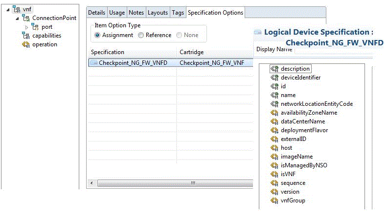
Description of ''Figure 3-1 VNF Service Configuration Model ''
The following example shows the elements in the technical actions file:
<technicalActionCalculator
    xmlns="http://xmlns.oracle.com/communications/inventory/actioncalculator"
    xmlns:invactcalc="http://xmlns.oracle.com/communications/inventory/actioncalculator"
    xmlns:xsi="http://www.w3.org/2001/XMLSchema-instance"
    xsi:schemaLocation="http://xmlns.oracle.com/communications/inventory/actioncalculator schemas/TechnicalActionCalculator.xsd">
    <invactcalc:action>
        <name>DEPLOY_VNF</name>
        <actionCode>DEPLOY_VNF</actionCode>
        <subject>
            <class>LogicalDevice</class>
        </subject>
        <target>
            <class>LogicalDevice</class>
        </target>
        <parameter>
            <name>serviceID</name>
            <type>string</type>
        </parameter>
        <parameter>
            <name>vnfID</name>
            <type>string</type>
        </parameter>
        <parameter>
            <name>vnfName</name>
            <type>string</type>
        </parameter>
        <parameter>
            <name>vnfdName</name>
            <type>string</type>
        </parameter>
        <parameter>
            <name>imageName</name>
            <type>string</type>
        </parameter>
    </invactcalc:action>

    <invactcalc:match>
        <invactcalc:diff>
            <invactcalc:path>/root/after/vnf/Assignment[@State='PENDING_ASSIGN'
                and /root/service[state!='PENDING_DISCONNECT']]/..</invactcalc:path>
        </invactcalc:diff>
        <invactcalc:action>DEPLOY_VNF</invactcalc:action>
        <invactcalc:anchor>.</invactcalc:anchor>
    </invactcalc:match>

    <invactcalc:generator>
        <invactcalc:action>DEPLOY_VNF</invactcalc:action>
        <invactcalc:condition>/root/after/vnf/Assignment[@State='PENDING_ASSIGN']</invactcalc:condition>
        <subject>.</subject>
        <target>.</target>
        <binding>
            <parameter>serviceID</parameter>
            <path>/root/service/id</path>
        </binding>
        <binding>
            <parameter>vnfID</parameter>
            <path>Assignment/id</path>
        </binding>
        <binding>
            <parameter>vnfName</parameter>
            <path>Assignment/name</path>
        </binding>
        <binding>
            <parameter>vnfdName</parameter>
            <path>Assignment/specification</path>
        </binding>
        <binding>
            <parameter>imageName</parameter>
            <path>Assignment/imageName</path>
        </binding>
    </invactcalc:generator>
</technicalActionCalculator>
About Technical Actions
In the technical actions file, for each technical action, you define the following elements:
-
action: This element declares a technical action, its signature, which contains the name and type of each parameter, and the type of its subject and target.
-
match: This element declares configuration differences that match an XPath expression.
-
generator: This element defines all the bindings of the configuration to the parameters, subject, and target of the action to be generated.
Creating a Technical Action File
In Design Studio, you create a technical action file for each Network Service specification and VNF Service specification.
To create a technical action file:
-
In Design Studio, switch to the Navigator view.
-
In the root directory of the cartridge, create the following folder structure:
model\content\product_home\config
-
Right-click on the config folder and create an XML file with the name ServiceSpecificationName_TechnicalActions.xml.
-
Copy the sample content from the sample cartridge to the XML file and modify it according to your solution requirements.
About the VNF Configuration Files
After a VNF is deployed, you can configure the VNF based on the configuration requirements of the VNF.
Note:
Configuration is not required for all VNFs. Configuration is required only for those VNFs that need additional configurations other than the configuration in the VNF's software image.To configure the VNF, the solution requires the following configuration files to be created:
-
VNFD_NameTemplate.conf
This is a VNF-specific configuration template in which you specify the placeholder fields for instance-specific parameters.
-
VNFD_NameConfig.xml
This is a configuration file in which you specify the VNF instance-specific configuration parameter values as name-value pairs.
The solution generates the VNFD_Name.conf configuration file based on the VNFD_NameTemplate.conf file and the VNFD_NameConfig.xml file.
The solution reads all the name-value pairs in the VNFD_NameConfig.xml file and replaces the placeholder fields in the VNFD_NameTemplate.conf file and generates the VNFD_Name.conf file.
The following text shows a sample configuration template for the Juniper vSRX VNF in the Juniper_vSRX_VNFDTemplate.conf configuration file:
   <rpc>
    <edit-config>
        <target>
            <candidate/>
        </target>
        <config>
            <configuration>
                <security>
                    <utm>
                        <custom-objects>
                            <url-pattern>
                                <name>bad-sites</name>
                                <value>{{site-name}}</value>
                            </url-pattern>
                        </custom-objects>
                    </utm>
                </security>
            </configuration>
        </config>
    </edit-config>
    </rpc>
The following example shows a sample configuration for the Juniper vSRX VNF in the Juniper_vSRX_VNFDConfig.xml configuration file:
<vnfConfiguration>
    <config>
        <param>
            <name>site-name</name>
            <value>www.example.com</value>
        </param>
        <sbiToPushConfiguration>
            <interface>netconf</interface>
            <interface-script></interface-script>
        </sbiToPushConfiguration>
        <action>null</action>
    </config>
    </vnfConfiguration>
About the Sample Network Protection Service Model
The Network Service Orchestration solution provides the following sample cartridges that you can use as references for designing and implementing network protection as a service on your network:
-
NPaaS_NetworkService. This sample cartridge contains functionality to implement a Network Protection service on your network.
-
Juniper_vSRX_VNF. This sample cartridge contains the functionality to implement a Juniper vSRX firewall as a VNF.
-
Checkpoint_NG_FW_VNF. This sample cartridge that contains the functionality to implement a Checkpoint firewall as a VNF.
Figure 3-2 shows how the Network Protection service is modeled in the sample Network Service cartridge.
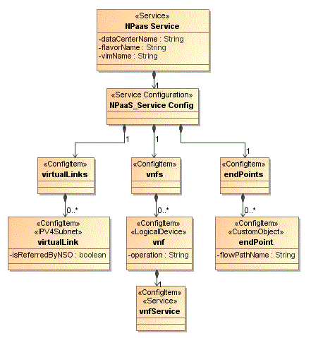
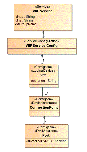
Figure 3-3 shows how a VNF service is modeled in the sample VNF cartridge.
The solution includes sample descriptor files for the sample Network Protection service and the constituent VNFs. The descriptor files enable you to define the behavior of the network service and the VNFs.
-
NPaaS_NSD.xml. This is the descriptor file for the Network Protection service.
-
Juniper_vSRX_VNFD.xml. This is the descriptor file for the Juniper vSRX firewall VNF.
-
Checkpoint_NG_FW_VNFD.xml. This is the descriptor file for the Checkpoint NG firewall VNF.
You open the descriptor files in Design Studio and specify the deployment requirements, operational behavior, and policies required by network services.
In the descriptor file:
-
Specify the networks that you want to create or reference. In the descriptor file, networks are represented as virtual link descriptors.
-
Specify the VNFs and the flow path that you want the network traffic to pass through.
-
Specify the CPU utilization and other parameters for each VNF in the network service.
See "About the Descriptor Files" for more information about the Network Service descriptor file.
See "About the VNF Descriptor" for more information about the VNF descriptor file.
The solution includes sample technical action files for the VNFs. The technical action files enable you to describe the actions for the VNFs in the VIM.
-
NPaaS_NSD_TechnicalActions.xml. This is the technical actions file for the Network Protection service.
-
Juniper_vSRX_ServiceDescriptor_TechnicalActions.xml. This is the technical actions file for the Juniper vSRX firewall VNF.
-
Checkpoint_NG_FW_ServiceDescriptor_TechnicalActions.xml. This is the technical actions file for the Checkpoint NG virtual firewall.
Implementing a Network Service By Using the Sample Cartridges
The sample network protection service uses the following software components:
-
UIM 7.3.2 and the Network Service Orchestration Solution 1.1 cartridges
-
OpenStack VIM, with Open vSwitch capability
-
OpenDaylight SDN Controller
-
Software images for the firewall VNFs
To implement the network protection service:
-
In OpenStack, create a tenant or reference an existing tenant with administrator privileges.
-
Create a management network or reference an existing management network that can be shared by all the components of the solution.
The management network requires, at a minimum:
-
One IP address for each:
-
Virtual machine on which UIM is installed
-
Virtual machine on which Open vSwitch is installed
-
Virtual machine on which OpenDaylight is installed
-
-
One IP address for each virtual machine on which you want to bring up the VNFs
-
-
Connect the management network and the external network to a virtual router. This enables you to use floating IP addresses for providing access to the data center.
-
Create a customer-side network that facilitates the customer's network traffic to reach the VNFs.
Table 3-1 shows a sample network and subnet configuration for the customer-side network.
-
Create an Internet-side network that facilitates the traffic from the customer-side network to the Internet.
Table 3-2 shows a sample network and subnet configuration for the Internet-side network.
-
Create packet-in and packet-out networks.
Table 3-3 shows a sample network and subnet configuration for the packet-in network.
Table 3-3 Sample Network and Subnet Configuration for Packet-in Network
CIDR IP Allocation Pool Gateway IP DHCP Enabled Additional Routes DNS Name Server 192.0.2.128/24
Start 192.0.2.129
End 192.0.2.140
-
Yes
None
None
Table 3-4 shows a sample network and subnet configuration for the packet-out network.
-
Start the OpenDaylight virtual machine on the management network.
-
Start the Open vSwitch virtual machines on the management network, customer-side network, Internet-side network, packet-in network, and packet-out network.
-
On the Open vSwitch virtual machine, run the following commands:
-
Create a steering bridge:
ovs-vsctl add-br steeringwhere steering is the name of the integration bridge.
-
Add the interfaces of the networks you created to the steering bridge:
ovs-vsctl add-port steering networkInterface
where networkInterface is the name of the network interface. For example, eth1.
ovs-vsctl add-port steering eth1
ovs-vsctl add-port steering eth2
ovs-vsctl add-port steering eth3
ovs-vsctl add-port steering eth4
ovs-vsctl add-port steering eth5
-
Set the IP address and port number of the OpenDaylight virtual machine as the controller to the steering bridge:
ovs-vsctl set-controller steering tcp:OpenDaylight_IPAddress
8 ovs-vsctl set bridge steering protocols="OpenFlow13"
where OpenDaylight_IPAddress is the IP address of the OpenDaylight virtual machine.
-
Get the port numbers:
ovs-vsctl -- --columns=name_of_port list Interface
where name_of_port is the name of the Open vSwitch port.
-
-
In Design Studio, open the nso.properties file and do the following:
-
Update the corresponding Open vSwitch port numbers of the network interfaces:
-
nso.ovs.pktInToOVSPort = ovsPort
where ovsPort is the Open vSwitch port number of the network interface that you attached to the steering bridge.
-
nso.ovs.pktInToOVSPort = 4
-
nso.ovs.pktOutToOVSPort = 1
-
nso.ovs.custNetToOVSPort = 5
-
nso.ovs.internetToOVSPort = 2
-
-
Update the following server details:
-
NSO_HOST: IPv4address
-
NSO_USERNAME: username
where IPV4address is the IP address and username is the username of the machine on which UIM is installed.
Note:
By default, the nso.properties file displays the username and password of the Network Service Orchestration solution user in plain text. You can encrypt the password by running the EncryptText ruleset in UIM.To encrypt the password:
-
Create a text file and type the password.
-
Save and close the file.
-
In UIM, run the EncryptText ruleset, and browse and specify the text file that contains the password in plain text.
UIM displays the encrypted password.
-
Copy the encrypted password and paste it in the nso.properties file.
-
-
Specify the following networks:
-
NPaaS_NSD.ManagementNetwork=management_network
where management_network is the name of the management network.
-
NPaaS_NSD.Data_IN=packet_in_network
where packet_in_network is the name of the packet-in network.
-
NPaaS_NSD.Data_OUT=packet_out_network
where packet_out_network is the name of the packet-out network.
-
-
Specify the name of the network service descriptor:
ServiceDescriptors = NPaaS_NSDwhere NPaaS_NSD is the name of the Network Service descriptor.
-
-
Open the NPaaS_NSD.xml file and set isReferenced to true.
-
Open the nfvi.properties file and update the odlManager path:
sdnController.ODL=com.oracle.communications.inventory.nso.nfvi.sdn.ODLManager -
In OpenDaylight, retrieve the OpenFlow ID by calling the following OpenDaylight REST API:
http://odl_IPaddress:port/restconf/operational/opendaylight-inventory:nodes/
where odl_IPaddress is the IP address and port is the port number of the OpenDaylight virtual machine.
-
In the nso.properties file, update the OpenFlow ID:
nso.ovs.bridge_id=openflow:OpenFlow_ID -
Redeploy the cartridges in Design Studio. See "Configuring UIM for the Network Service Orchestration Solution" for information about deploying the cartridges in the specified order.
-
Register the VIM by calling the corresponding RESTful API. See "Integrating the VIM with the Solution" for instructions.
-
Discover the VIM resources. See "Discovering VIM Resources" for instructions.
Designing New Network Services and VNF Services
You can define and model network services and VNFs depending on the network functions that you want to virtualize on your network.
To define and model network services and VNFs, you work in Design Studio. In Design Studio, you define specifications and properties for your network services, VNFs, and their hierarchical and related components.
To model a network service with a VNF, you create two cartridges in Design Studio: one cartridge for the VNF and one cartridge for the network service.
In the cartridge for the Network Service, do the following:
-
Specify the following UIM entity specifications:
-
One Service specification for the Network Service
-
One Service Configuration specification for the network service
-
-
Create a technical actions file for the Network Service specification. See "Creating a Technical Action File" for more information.
-
Create a network service descriptor file for the Network Service specification. See "Creating a Descriptor File" for more information.
-
Create a custom properties file for the Network Service specification.
-
Create custom code for extension.
In the cartridge for the VNF Descriptor, do the following:
-
Specify the following UIM entity specifications:
-
One Service specification for the VNF
-
One Service Configuration specification for the VNF
-
A Logical Device specification for the VNF
-
-
Create a technical actions file for the VNF Service specification. See "Creating a Technical Action File" for more information.
-
Create a VNF descriptor file for the VNF Service specification. See "Creating a Descriptor File" for more information.
-
Create a configuration file for the VNF.
-
Create a post-configuration template configuration file for the VNF. See "About the VNF Configuration Files" for more information.
-
Create a template file for the VNF.
-
Create custom code for extension.