1 Introduction to Disaster Recovery
Best Practices for Enterprise Disaster Recovery (DR) basically consist of designing and implementing fault-tolerant hardware and software systems that can survive a disaster ("business continuance") and resume normal operations ("business resumption"), with minimal intervention and, ideally, with no data loss. Building fault-tolerant environments to satisfy Enterprise DR objectives and real-world budget constraints can be expensive and time consuming and requires a strong commitment by the business.
DR plans typically address one or more of these types of disasters:
-
Extensive or extended IT facility damage due to natural disaster (earthquake, storm, flooding, and so forth) or other causes (fire, vandalism, theft, and so forth).
-
Extended loss of IT facility critical services, for example., loss of power, cooling or network access.
-
Loss of key personnel.
The DR planning process begins by identifying and characterizing the types of disasters a business must survive and resume operations. The planning process identifies high-level business continuance (BC) and business resumption (BR) requirements, including the required degree of fault tolerance. The product of DR planning is a recovery and resumption architecture for fault-tolerant systems, applications and data to support these requirements subject to established constraints. Typical DR constraints include recovery time objective (RTO), recovery point objective (RPO) and available budget. The DR architecture plus the business constraints leads to DR procedures that integrate all system elements in a true "end-to-end" fashion to guarantee predictable results for the overall DR process.
Fault tolerant systems typically achieve robustness and resiliency through redundancy. Often achieved at great expense, a fully redundant system has no single point of failure within its architecture and can operate during and resume operations from the worst possible disaster within its limits. Space shuttle and aircraft flight control systems are good examples of fully-redundant systems. Less critical IT applications typically use less robust systems with lower redundancy. These systems are less costly to construct and will necessarily incur a service outage after disaster strikes, during which time the business works to reinstate its recoverable systems, applications and data.
Ultimately, the nature of a business, its customer requirements, and the available budget for DR are key factors in formulating DR requirements. A comprehensive DR solution can cost a lot...but it has to be architected. You cannot just throw money, hardware, and software at a potential disaster and hope to survive and resume your business operations. If you plan and architect intelligently, however, you may have to incur longer outages, degraded service, or both until full services can resume, but you can still have a dependable, limited DR solution.
Understand, however, that perhaps no amount of planning can anticipate and respond to all possible DR scenarios. For example, what begins as an apparently trivial problem on one system can spread over time to affect other systems in different ways, all adding up to a disaster for which there is no recovery scenario. Similarly, a business's ability to honor service agreements may suffer if key assumptions do not hold true...for example, if key parts or service are unavailable, or if the DR provider's delivery capability is not as robust as advertised. The real key, however is that if a disaster occurs that exceeds the worst-case scenario that you planned for, recovery may not be possible.
Defining the Recovery Time Objective (RTO)
RTO is a service level objective of the time it takes to achieve a desired operational capability after a disaster has occurred. For example, business requirements may dictate the RTO that all production systems are up and running at 80% of pre-disaster capability within 30 minutes of any unplanned outage that would last longer than one hour (if no DR capability existed). RPO processing time, availability of qualified IT staff and the complexity of manual IT processes required after a disaster are examples of constraints that may shape RTO determination. RTO does not apply to fully fault tolerant systems because these systems recover implicitly during and after a disaster, with no service interruption.
DR planners might set different RTOs for some or all of the defined BC requirements. Different types of business operations may require different RTOs, for example different RTOs for online systems versus batch windows. Further, different RTOs may apply in stages for a phased DR plan, where each phase has a defined RTO. Even further, a recoverable application may have different RTOs for each of its various service levels.
BC data availability requirements are extremely important to RTO planning. When data that must be input to the DR recovery process is not present at the disaster recovery site, the time it takes to retrieve the data on-site will delay RTO. For example, data residing in offsite storage vaults will take time to retrieve. Recovery can proceed quickly if up-to-date input data is duplicated at the recovery site before the start of disaster recovery operations.
Defining the Recovery Point Objective (RPO)
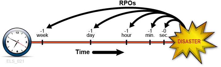
RPO is a business continuance objective that dictates the business state, or business currency, that is achieved after the disaster recovery process has reinstated all recoverable systems. Conceptually, RPO is a known "rollback" or synchronization target state before disaster. That is, RPO is the post-disaster recovery point from which interrupted recoverable applications can resume processing. All transactions occurring during the interval between the RPO and the time of disaster are unrecoverable. RPO does not apply to fully fault tolerant systems because disaster does not affect the business continuance of these systems.
Figure 1-1 illustrates RPO concepts by suggesting various recovery points for DR planners to consider. Planning must ensure the desired RPO is feasible vis-à-vis the chosen RTO and vice versa. Generally, disaster recovery plans that mandate RPOs nearer to the time of disaster require greater fault tolerance and are more costly to implement versus more distant RPOs. As with RTO, DR planners might set different RPOs for different BC requirements, DR plan phases or application service levels.
More broadly, RPO planning must identify all supporting elements that must be present to reinstate each recoverable system, including data, metadata, applications, platforms, facilities and personnel. Planning must also ensure these elements are available at the desired level of business currency for recovery. BC data currency requirements are especially crucial to RPO planning. For example, if BC requirements dictate a one-hour RPO, any data or metadata that feeds the recovery process must be current up to the RPO, otherwise the RPO cannot be achieved. The organization's DR processes will specify the procedures to achieve all defined RPOs within the stated RTOs.
System metadata required for RPO recovery includes OS catalog structures and tape management system information. These items must be updated during the disaster recovery process to enable all of the chosen RPOs. For example, to ensure consistency among the various metadata inputs to the DR recovery process, existing data sets that will be recreated at RPO must be uncataloged; data sets updated between the RPO and the time of disaster must be restored to the version that existed at or before the RPO; and any tape-related catalog changes must be synchronized with the tape management system.
Handling Temporary Outages
Disaster recovery provides remediation for very long-term outages that would render a production site unusable for an extended period. While the remainder of this introduction addresses disaster recovery practices, it might be just as important to develop procedures to mitigate relatively brief outages that could negatively affect production if left unchecked. Consider, for example, a service outage where certain hardware or network facilities are unavailable for an hour or two, but production can continue during this outage in ”degraded mode” with a few quick, temporary adjustments. A temporary outage procedure would document how to isolate the problem, what changes to make, whom to notify and how to revert to the normal operating environment after service is restored.
Key Concept: Synchronization Point Recovery
Restarting production applications at defined RPOs is a key activity performed during true disaster recovery and during DR testing. The most resilient DR environments will ensure every recoverable application, whether sourced or developed in-house, enforces a core DR requirement: namely, that the application is designed to restart from a planned epoch, called a synchronization point, to mitigate the effects of an unscheduled interruption during its execution. When an interrupted application is restarted at a synchronization point, the results are the same as if the application had not been interrupted.
The restart procedure for a recoverable application depends on the nature of the application and its inputs. Quite often, the application restart procedure for true disaster recovery or DR testing is the same procedure used for restarting the application should it fail during a normal production run. Where possible, reusing production restart procedures for true disaster recovery or DR testing simplifies the creation and maintenance of DR procedures and leverages these proven procedures.In the simplest case, a recoverable application is a single job step with only one synchronization point, which is the beginning of the program invoked by that step. In this case, the recovery procedure might be as simple as resubmitting the interrupted job. A slightly more complex restart procedure might involve uncataloging all of the output data sets produced by the application during its last run, and then restarting the application.
The restart procedures for applications having multiple internal synchronization points to choose from might not be so simple. Applications that use checkpoint/restart techniques to implement these synchronization points periodically record their progress and can, for example, use recorded checkpoint information to restart at the last internal synchronization point recorded before an interruption. Restart procedures will conform to the requirements of each synchronization point. When checkpointing is in use, data sets associated with a checkpoint must not be expired, uncataloged or scratched while the checkpoint remains valid for application recovery.An easy way to establish a synchronization point for a job step that modifies its existing input data sets is to make a backup copy of each modifiable data set before running the step. These modifiable input data sets are easily identified by searching for JCL attribute DISP=MOD in DD statements or in dynamic allocation requests. If a job step failure or interruption, simply discard any modified input data sets, restore those input data sets from backup copies, and restart the step from the restored copies. These backup copies are also useful to restart a failed or interrupted job step that had expired, uncataloged or scratched the originals.
Relating RPO to Synchronization Point Recovery
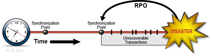
When the RPO aligns with a synchronization point, performing the application restart procedure that was developed for this synchronization point will resume the application from this origin as if no interruption has occurred (Figure 1-2). All transactions processed after this RPO up to the disaster are presumed unrecoverable.
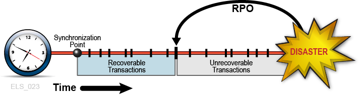
At other times, BC requirements may justify placing the RPO between synchronization points. In these cases, inter-synchronization point recovery relies on supplemental data describing any critical application state changes or events occurring after the most recent synchronization point is established. Consider, for example, the RPO of one minute before disaster. Suppose a recoverable application is designed to use checkpoints to record its progress, but suppose the overhead of taking these checkpoints at one-minute intervals is intolerable. One solution is to take checkpoints less frequently and to log all transactions committed between checkpoints. This transaction log then becomes supplemental input data used by the checkpoint recovery process to restart from an RPO beyond the most recent synchronization point. In this example, the application restart procedure accesses the most recent checkpoint data and applies the supplemental transaction log to reinstate all committed transactions processed after the checkpoint and before the RPO (Figure 1-3) In this way, synchronization point recovery can achieve a target RPO using input data from multiple sources. All transactions processed after the RPO up to the disaster are presumed unrecoverable.
Figure 1-3 RPO Between Synchronization Points
Description of ''Figure 1-3 RPO Between Synchronization Points''
Planning for Data High Availability (D-HA)
Data is often one of the most precious assets held by a business. Many companies take great care and make extra investment to safeguard business-critical data against loss, and to ensure data is available for its intended purpose when needed. A firm that cannot cope with critical data loss might well suffer from disastrous consequences.Perhaps the most common way to protect against data loss is by storing copies of critical data on different storage media or subsystems, and by storing some of these copies at different physical locations. Copies stored on removable storage media, including magnetic cartridge tape, CD-ROM and DVD are typically vaulted at offsite storage locations. Extra copies are also typically stored on-site at IT facilities where applications can process that data.Creating and storing critical data copies increases data redundancy and improves data fault tolerance. For removable media, and in particular for magnetic cartridge tape, increasing data redundancy alone is usually not enough to ensure data is also highly available to the applications that will use it. For example, Oracle's VSM system for mainframe virtual tape stores data on physical tape volumes called MVCs. VSM can make MVC copies automatically to improve data redundancy and to reduce risk due to a media failure or a misplaced tape cartridge. A production VSM system utilizes many specialized hardware components to retrieve data stored on an MVC, including a VTSS buffer device, an automated tape library and library-attached tape drives called RTDs, which are also attached to the VTSS buffer device. Host applications depend on all of these VSM components operating together to retrieve data from MVCs. Even though most people would not regard a single component failure as a disaster on par with losing an entire data center in an earthquake, it certainly might become impossible to retrieve any MVC data if a single VSM critical component fails without a backup, no matter how many redundant MVC copies exist. Thus, while creating MVC copies is a proven best practice to mitigate vulnerability and risk, it does not always sufficiently guarantee data high availability (D-HA) in the presence of faults.D-HA requirements are key business continuance requirements for DR planning. D-HA is typically achieved by increasing redundancies to eliminate single points of failure that would prevent applications from accessing data amidst storage system faults. For example, a VSM system that includes redundant components improves VSM system fault tolerance. Installing multiple VTSS devices, redundant SL8500 handbots and multiple RTDs aims to eliminate VSM single points of failure along the data path from the application to the critical data stored on an MVC. The VSM architecture is designed throughout to support adding redundant components to increase fault tolerance and promote D-HA.
Highly-Available Physical Tape
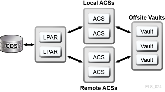
Oracle's mainframe tape automation solutions enable D-HA for physical tape applications by storing redundant copies of data in different ACSs within a tapeplex, that is, within a tape complex mapped by a single CDS. For example, applications running at an IT facility with a single tapeplex can easily store duplicate copies of tape data sets in one or more ACSs within that tapeplex. This technique improves D-HA by adding redundant media, tape transports and automated tape libraries. In a simple case, an application stores redundant copies of a critical data set on two different cartridge tapes in a single SL8500 library with redundant electronics, dual handbots on each rail and two or more library-attached tape transports on each rail that are compatible with the data set media. To remove the SL8500 library as a potential single point of failure, a second SL8500 is added to the ACS to store even more redundant copies of the critical data set. To eliminate the IT facility itself as a single point of failure, redundant data set copies can be vaulted offsite or created at a remote ACS with channel-extended tape transports (Figure 1-4).
Figure 1-4 FD-HA Physical Tape Configuration
Description of ''Figure 1-4 FD-HA Physical Tape Configuration''
You can also make two or more copies of physical tapes in different physical locations when each location has its own independent CDS, that is, when the hardware at each location represents a separate tapeplex. By using the SMC Client/Server feature and defining policies that direct data set copies to a remote tapeplex, jobs can create tape copies in an ACS in another tapeplex with no JCL changes.
Highly-Available Virtual Tape
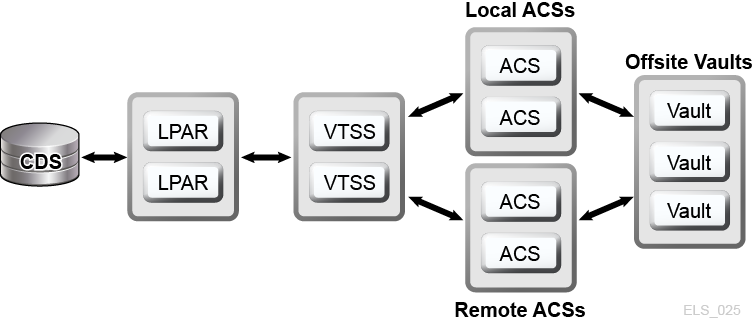
VSM provides MVC N-plexing and clustering technologies to enable D-HA for mainframe virtual tape. VSM N-plexing involves creating multiple MVC copies (for example, duplex, quadplex) in one or more ACSs for greater redundancy (Figure 1-5). ACSs receiving N-plexed copies can be local libraries or remote ACSs with channel-extended tape transports. VSM migration policies control the movement of VTSS buffer-resident VTVs onto local or remote MVCs, which may be cycled to offsite vaults.
Figure 1-5 D-HA VSM N-plexing Configuration
Description of ''Figure 1-5 D-HA VSM N-plexing Configuration''
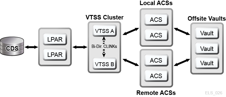
A VSM cluster comprises two or more VTSS devices (nodes) networked for data interchange over a communications link (CLINK.) CLINKs are either unidirectional or bidirectional channels. The simplest VSM cluster configuration consists of two VTSS nodes in the same tapeplex linked with a unidirectional CLINK, but bi-directional CLINKs are commonly deployed (Figure 1-6). Each cluster node may be located at a different site. VSM uni-directional storage policies control the automatic replication of virtual tape volumes (VTVs) from VTSS A to VTSS B over a unidirectional CLINK. Bidirectional storage policies and bi-directional CLINKs enable VTSS A to replicate to VTSS B and vice versa.
Figure 1-6 D-HA VSM Cluster Configuration
Description of ''Figure 1-6 D-HA VSM Cluster Configuration''
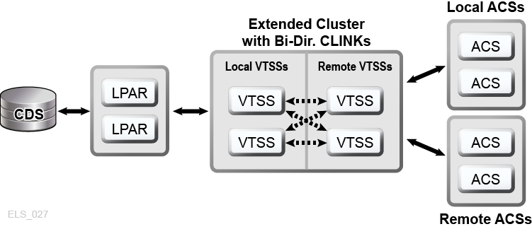
VSM Extended Clustering enables many-to-many connectivity among three or more VTSS devices in a tapeplex for even higher degrees of data availability (Figure 1-7). Installing VTSS cluster devices at two or more sites within a tapeplex as shown increases redundancy by eliminating each site as a single point of failure.
Figure 1-7 D-HA Extended Cluster Configuration (offsite vaults not shown)
Description of ''Figure 1-7 D-HA Extended Cluster Configuration (offsite vaults not shown)''
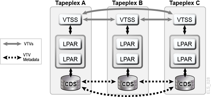
A VSM Cross-Tapeplex Replication cluster (CTR cluster) allows VTSS cluster devices to reside in different tapeplexes and provides the capability to replicate VTVs from one tapeplex to one or more other tapeplexes, enabling many-to-many cluster replication models over uni-directional or bi-directional CLINKs (Figure 1-8). Sending and receiving tapeplexes may be located at a different sites. Replicated VTVs are entered into the CDS for the receiving tapeplex as read-only volumes. This provides strong data protection against alteration by applications running in the receiving tapeplex. The CDS for the receiving tapeplex also indicates the CTR-replicated VTV copies are owned by the sending tapeplex and, as added protection, CTR ensures a tapeplex cannot modify any VTV it does not own.
Figure 1-8 D-HA VSM Cross-Tapeplex Replication Configuration
Description of ''Figure 1-8 D-HA VSM Cross-Tapeplex Replication Configuration''
D-HA and Synchronization Point Recovery
Creating multiple copies of physical volumes (MVCs or non-MVCs) improves data redundancy but these copies pose special considerations for synchronization point recovery. The most important aspect of synchronization point recovery is ensuring the data created at a synchronization point stays in a read-only state while it remains valid for disaster recovery usage. This means physical tape volume copies that could be used for disaster recovery must be kept in a read-only state. One way to do this is to send these copies to an offsite vault location where no tape processing capability exists. Be aware that any unprotected copies that undergo alteration are unusable for synchronization point recovery because the updated contents no longer reflect the associated synchronization point.Virtual tape environments add an extra dimension to managing multiple volume copies for synchronization point recovery. VTV copies can exist in multiple VSM buffers and on multiple MVCs all at the same time. Even when all MVCs for a given VTV are vaulted offsite, VTV copies remaining on-site in VSM buffers can be modified. An updated buffer-resident VTV copy must not be used for synchronization point recovery unless this VTV belongs to a new synchronization point that invalidates the offsite copies vaulted for disaster recovery usage.
Conducting True Disaster Recovery
The success of a true disaster recovery operation rests on having an adequate DR site, trained personnel, a proven DR procedure, a recoverable production workload with synchronization points to meet defined RPO(s), and all input data and system metadata necessary to attain these RPOs. Input data and system metadata must be accessible at the DR site when needed and must be available at the required level(s) of currency. With careful planning, thorough preparation and well-rehearsed execution, true disaster recovery operations can flow smoothly according to plan to achieve the defined RPO(s) and RTO(s.)Production data generated at the DR site must be adequately protected while the DR site is functioning as a production site. Suppose, for example, the D-HA architecture requires the production workload to replicate redundant data copies at three remote sites, and suppose the DR site is one of these remote replication sites before disaster. When the production site experiences a disaster and its workload is moved to the DR site, the DR site can no longer serve as a remote replication site for the production workload now running locally at that site. To meet the D-HA requirement of three remote replication sites, a new third remote replication site must be brought online for as long as production remains at the DR site. This example illustrates how a thorough analysis of D-HA requirements will enable DR planners to address all critical D-HA requirements that must be met when production is moved to a DR site.A comprehensive DR plan encompasses not only the activities to reinstate production at the DR site but also includes the process to vacate the DR site when the production site is repaired and ready for business, assuming the DR site is only a temporary substitute for production. For example, when the production site is ready to resume operation, production data must be reinstated at that site. Methods include bi-directional clustering between the DR site and the production site, allowing enough time for production work running at the DR site to repopulate the former production site by data replication. It may, however, be necessary, or more timely or efficient, to simply transport physical MVCs back to the reinstated production site. The chosen methods will depend on the post-disaster recovery requirements.
Planning for DR Testing
True disaster recovery readiness is assessed by testing the efficiency and effectiveness of DR systems and procedures at recovering a production workload at a designated DR test site. The DR test environment may be a dedicated DR test platform, but usually it is more economical to share resources between production and DR test systems. DR testing performed in parallel with production and using resources shared with production is called concurrent DR testing. If an application must execute in parallel on production and DR test systems, DR planners should ensure these two instances of the application will not interfere with each another while they run concurrently. Isolating the production and DR test systems on separate LPARs and limiting access to production data from the DR test system usually provides sufficient separation.DR testing is often conducted piecemeal to allow targeted testing of different applications at different times, rather than testing recovery of the entire production environment all at once. Targeted testing is key to reducing the amount of dedicated hardware required for the DR test system. For example, if DR testing for a recoverable application requires only a small subset of VSM resources, those resources can be shared between the production and DR test systems and reassigned to the DR test system for the DR test cycle. This approach reduces DR test system hardware expense at the risk of impacting production system performance while the DR test is running. Typically, however, a DR test cycle dedicates only a small percentage of shared resources to the DR test system, and the diminished production environment is not greatly impacted by parallel DR testing. Nevertheless, some organizations have policies against altering or impacting production to facilitate DR testing.Your auditors might require an exact match between DR test results and production results to certify the DR recovery process. One way to meet this requirement is to establish a synchronization point just ahead of a scheduled production run, save a copy of the production results, recover the production run at this synchronization point on the DR test site and compare the output against the saved production results. Any difference between results highlights a gap that must be investigated. Failure to address gaps in a timely fashion could put an organization's true disaster recovery capability at risk. No matter whether a DR test is designed to recover a complex workload or a single application, the DR test process must be performed using the same procedures that would be used for true disaster recovery. This is the only sure way to demonstrate the DR test was successful.
Data Movement for DR Testing
There are two methods to stage application data for DR testing at a DR test site: physical data movement and electronic data movement. Physical data movement involves transporting physical tape cartridges to the DR test site in a process described below called Physical Export/Import. Electronic data movement uses remote tape drives, remote RTDs or VSM cluster techniques to create copies of application data at a DR test site. Both of these data movement methods enable DR testing, but electronic data movement avoids physical data transfer and any potential problems with lost tapes, and so forth Electronic transfer also improves time to access data by placing it where needed for true disaster recovery, or by staging data in a VSM buffer ahead of a DR test cycle. Electronic data movement for virtual volumes can be done within a single tapeplex by using VSM Extended Clustering, or between two tapeplexes by using Cross-Tapeplex Replication. For data within a single tapeplex, Oracle's Concurrent Disaster Recovery Test (CDRT) software streamlines DR testing.
DR Testing With Physical Export/Import
Suppose you want to perform DR testing for a production application that uses virtual and physical tape. Your goal is to test this application at the DR test site by repeating a recent production run and verifying the test output matches the recent production output. In preparation you'll need to save copies of any input data sets used by the production run and a copy of the production output for comparison.Suppose the DR test site is isolated and shares no equipment with production. You could conduct the DR test using this Physical Export/Import process.
Production Site:
-
Make a copy of the requisite VTVs and physical volumes.
-
Export those VTV copies.
-
Eject associated MVC copies and physical volume copies from the production ACS.
-
Transport ejected MVCs and physical volumes to the DR test site.
DR Test Site:
-
Enter transported volumes into the DR ACS.
-
Synchronize OS catalogs and tape management system with the entered volumes.
-
Import VTV/MVC data.
-
Run the application.
-
Compare results.
-
Eject all volumes entered for this test.
-
Transport ejected volumes back to production site.
Production Site:
-
Enter transported volumes back into the production ACS.
This process allows DR testing to proceed safely in parallel with production since the DR test system is isolated from the production system. The DR test system has its own CDS, and the DR test process as above enters volume information into the DR test CDS in preparation for the DR test. This enables the recovered application to test with the same volumes and data set names it uses in production.Physical Export/Import incurs site expenses for physical tape handling and courier expenses to transport tape cartridges between the production and DR test sites. Sensitive data moved by courier should be transported on encrypted tape cartridges. DR testing timeliness is affected by the time spent transporting and handling the tape cartridges moved between sites.
DR Testing With CDRT
With planning and with sufficient hardware at the production and DR sites, CDRT combined with electronic data movement can eliminate the need to transport physical tape cartridges to the DR site and enables concurrent DR testing more economically than maintaining an isolated, dedicated DR test site. CDRT enables DR testing of almost any production workload, configuration, RPOs or RTOs imaginable. The DR test procedure will include a few extra steps to start CDRT and clean up after a DR test.Before running a DR test with CDRT, you should electronically move all of the application data and system metadata (OS catalog information and tape management system information) needed for the test to the DR test site. You can move application data electronically with VSM clustering or by migrating VTV copies to MVCs at the DR site. You then use CDRT to create a special CDS for the DR test system that mirrors the production CDS. The production and DR test systems are separate environments, and the DR test environment will use the special DR test CDS instead of the production CDS. Because CDRT creates the DR test CDS from information in the production CDS, it contains metadata for all of the volumes that were electronically moved to the DR test site before the DR test. This enables DR test applications to use the same volume serial numbers and tape data set names used in production.CDRT enforces operational restrictions on the DR test system to prevent the DR environment from interfering with the production environment. You can strengthen these protections by using ELS VOLPARM/POOLPARM capabilities to define separate volser ranges for MVCs and scratch VTVs for exclusive use by CDRT. CDRT allows the DR test system to read from production MVCs and write to its own dedicated pool of MVCs that is logically erased after each DR test cycle.For virtual tape applications, CDRT requires at least one dedicated VTSS device for the duration of the DR test cycle. These dedicated VTSSs can be temporarily reassigned from production to facilitate a DR test, and the DR test VSM system may access production ACSs in parallel with the production workload. Figure 1-9 and Figure 1-10 illustrate splitting a production VSM cluster to loan a cluster device to the CDRT DR test system, in this case VTSS2 at the DR test site. When this cluster is split, you must alter production policies to substitute migration for replication so VTSS1 will create redundant VTV copies at the DR site in ACS01, and so VTSS1 will not fill to capacity while the cluster is split. VTSS2 is taken offline to production and brought online to the DR test LPAR. In Figure 1-9, CDRT has created the DR test CDS from a remote copy of the production CDS. Only the production system may access volumes in VTSS1 and ACS00 throughout the DR test cycle, and only the DR test system may access VTSS2. The production and DR test systems share concurrent access to volumes in ACS01. Figure 1-9 and Figure 1-10 maintaining a remote copy of the production CDS at the DR test site, for example by remote mirroring, to ensure an up-to-date production CDS is available at the DR site for true disaster recovery use. Note, however, that the DR test CDS created by CDRT from the remote CDS copy is a special DR test version of the production CDS only for use by CDRT.Before re-forming the production cluster after the DR test cycle has ended, the DR VTSS must be purged to avoid production data loss, as would happen if VTSS2 contained a newer version of a VTV that also existed in VTSS1. You must also alter production policies to revert from migration to replication when the cluster is re-formed.If splitting a production cluster as shown here is not an option, an alternative is to maintain a separate VTSS at the DR site exclusively for DR testing. In this case, VTVs needed for the test will be recalled from MVC copies.
Figure 1-9 Production Cluster with Remote Cluster Node VTSS2 at DR Test Site
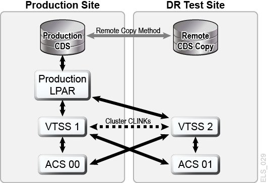
Description of ''Figure 1-9 Production Cluster with Remote Cluster Node VTSS2 at DR Test Site''
Figure 1-10 Production Configuration with VTSS2 Loaned for CDRT DR Testing
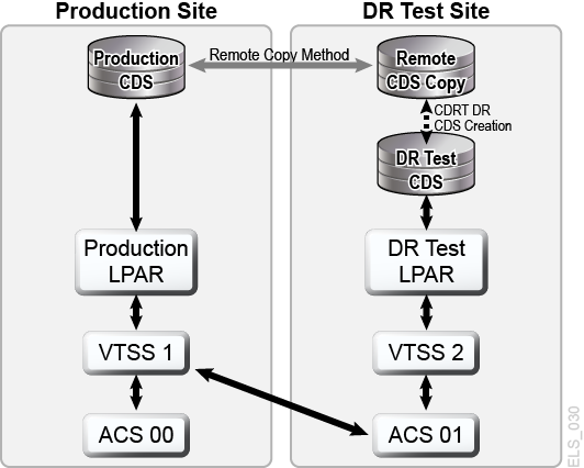
Description of ''Figure 1-10 Production Configuration with VTSS2 Loaned for CDRT DR Testing''
DR Testing with VSM Cross-Tape Replication
VSM Cross-Tapeplex Replication enables symmetric, clustered, production tapeplex designs that facilitate DR testing without using CDRT, without requiring dedicated VTSS hardware purely for DR testing and without altering the production environment for DR testing. For example, CTR enables each production tapeplex to replicate data to the other production tapeplexes in the same CTR cluster. Production CTR peer-to-peer clusters can eliminate the need for a dedicated DR test site. CTR enables many different types of clustered tapeplex designs and facilitates DR testing of any production workload or configuration, with any feasible RPOs or RTOs.In a simple example, a bi-directional CTR cluster joins two production tapeplexes symmetrically, and each tapeplex replicates data to the other TapePlex (Figure 1-11). A receiving tapeplex enters a replicated VTV into its CDS in read-only status and marks the VTV as owned by the sending tapeplex. In this example, DR testing for a tapeplex A application involves replicating application data at tapeplex B and recovering the application on tapeplex B.
Figure 1-11 Symmetric Production CTR Cluster for DR Testing
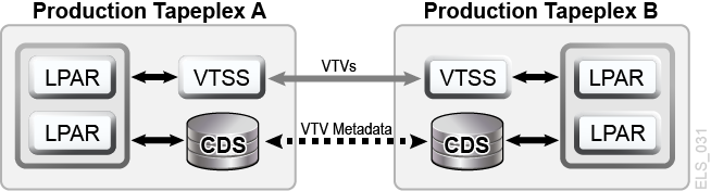
Description of ''Figure 1-11 Symmetric Production CTR Cluster for DR Testing''
The symmetry of this peered CTR cluster design means the recovered application being tested at the peer site runs the same during a DR test as during production. The peer CDS contains all the replicated volume information needed for DR testing, which proceeds in parallel with production, and the same VTSS hardware supports concurrent use by production and DR test workloads. Production VTSS clusters may exist within each TapePlex and need not be split to share hardware across tapeplexes for DR testing. The production tapeplex on which application DR testing is performed cannot modify any CTR-replicated VTVs, so all replicated production data is fully protected during the DR test cycle. Most importantly, CTR-based DR testing guarantees a validated DR test procedure will deliver identical results during true disaster recovery.SMC host software will issue a message if an attempt is made to update a CTR-replicated VTV, which serves to identify the application as one that modifies an existing input data set. Following best practices for managing synchronization points as above, you should ensure the production environment saves a copy of this data set before the application modifies it, should a backup copy be needed for synchronization point recovery.