| Oracle® Healthcare Master Person Index Relationship Management User's Guide Release 4.0 E71323-02 |
|
|
PDF · Mobi · ePub |
| Oracle® Healthcare Master Person Index Relationship Management User's Guide Release 4.0 E71323-02 |
|
|
PDF · Mobi · ePub |
The relationship management policies are used to specify custom business logic and process logic for a variety of relationship management transactions and events. The relationship policy is pluggable and written in standard groovy script. The custom relationship policy is loaded in the relationship management task table and identified by the reserved system task names. By default, the relationship management contains the default relationship policies which define the default business logic and process logic. The default business logic and process logic satisfy common use cases. You must understand the supported common use cases to see if your business cases are covered during the solution design phase. You must define and create your relationship policy for your business logic and process logic.
The relationship management supports the following types of relationship policies:
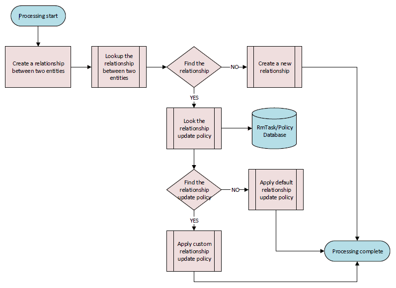
Relationship Update Policy: The relationship update policy defines processing logic on how to update or merge the attributes of two relationships when two relationships get updated or merged. The default strategy is 'most recent modified'. This strategy ranks the field values from the incoming message in descending order according to the time that the relationship was last modified. The value populated in the relationship comes from the most recently modified relationship. Each relationship type can define its own update policy. The policy is triggered by the relationship management when the relationship management creates a relationship between two entities while the two entities already have the same relationship.
Relationship Event Policy: The relationship event policy is a set of relevant policies and defines processing logic on how to process events from the incoming message. ADD event is for adding a new entity. MRG event is for merging two entities to be one. UNMRG event is for splitting one entity to two entities. These events are coming from the integrated MPI applications or integration tier application. The event policy is triggered by the relationship management when the user invokes the event synchronization REST API.
For any inbound message of requesting to establish a relationship of a specific relationship type between the source entity and the target entity, the same relationship between these two entities might exist already in the relationship management database, the difference between the newly attempted relationship and the existing relationship can be only with changes of the attribute values such as expiration date or adding new attributes. Therefore, how to update the existing relationships is the business decision. For example,
Allow one relationship instance of a specific relationship type between the two entities, merge the new relationship and the old relationship based on the business use cases
Allow multiple relationship instances of a specific relationship type exist between the two entities such as Doctor A is PCP of Patient B at the different clinics.
A pluggable relationship update policy of a relationship type manages how to update the existing relationships for various use cases in the relationship management database. This provides flexibility to customize the update relationship business logic and process for satisfying different use cases.
Figure 6-1 illustrates the process steps, and includes the triggering process of the default or custom relationship update policy.
Figure 6-1 Relationship Update Policy Processing Dataflow
The following are the strategies of the default relationship update policy:
You can create only one singular relationship between two entities
Update the existing attributes of existing relationship based on the most recent modified date
Add the new attributes of the existing relationship based on the relationship type metadata
Each relationship type can be associated with a specific custom update policy. This section explains how to customize the relationship update policy. To customize the update policy, perform the following steps:
Define the custom update business and process logic
Implement the custom update policy interface in groovy script.
Create the policy interface implementation file name with .groovy extension file name. For example, CustomPatientOfUpdatePolicyImpl.groovy.
Load the custom update policy interface implementation either using the relationship management Metadata REST API or the relationship management data manager by assigning a unique policy task name.
Register a new custom relationship policy using the management REST API:
POST /management/tasks/{task}
For example,
POST /management/tasks/CustomPatientOfUpdatePolicyImpl
{"name": "CustomPatientOfUpdatePolicyImpl"}
Upload the custom relationship update policy script groovy file using the management REST API:
PUT /management/tasks/{task}files
For example,
PUT/management/tasks/CustomPatientOfUpdatePolicyImpl/files
CustomPatientOfUpdatePolicyImpl.groovy
Update the update policy task of the relationship type using metadata REST API:
PUT /metadata/relationships/{name}
For example,
PUT /metadata/relationships/patient-of
{"name": "patient-of",
"task": {"name": "CustomPatientOfUpda
   "description": "customized update policy for updating patient-of relationship"}
}
Now, you can create a new relationship of the same relationship type between two entities that are already linked by the existing relationship. The result will be a single instance of the relationship for the same relationship type.
package oracle.hsgbu.ohmpi.rm.policy;
import java.util.List;
import oracle.hsgbu.ohmpi.rm.data.Relationship;
/**
*  Relationship UpdatePolicy interface
* @author <author_name>
*/
public interface UpdatePolicy {
/**
* Apply business and process logic of updating the existing relationship
* @param oldRelationship The existing relationship
* @param newRelationship The newly attempted relationship
* @return List<Relationship> A list of updated relationships
* @throws RelationshipPolicyException Throw exception if any error occurs
*/
List<Relationship> apply(Relationship oldRelationship, Relationship newRelationship)
   throws RelationshipPolicyException;
}
To implement the relationship update policy interface, you must have the ohmpi-rm-client.jar file under your relationship management project folder.
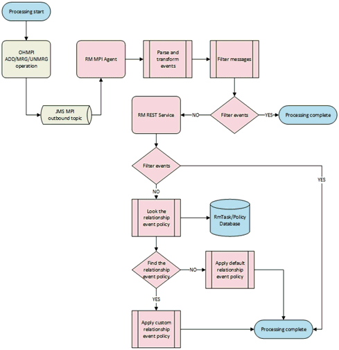
The OHMPI is setup to deliver JMS outbound notification for operations such as an update or a merge and a un-merge. When an operation occurs, the OHMPI creates an event message in XML and sends the event message to a JMS topic to notify external integrated applications of changes in data. The RM is integrated with the OHMPI applications and reacted to the OHMPI notification events by subscribing the JMS topic. The events are broadcasted from the OHMPI applications through the JMS topic to the RM MPI agent. And the RM MPI agent transforms the XML events to the messages in the RM format and sends to the RM by invoking the RM REST API. The RM takes the expected actions according the events. The following are the six events: ADD, MRG, UNMRG, DEA, REA, and UPD. This release provides the default business and processing logic for the following events:
ADD: When a new entity, such as Patient or IndProvider is added and a new enterprise object is added in the OHMPI, the OHMPI generates ADD event and publishes it to the MPI JMS topic. The ADD event contains the event type, the domain type, the EUID, the SBR and the all the necessary information.
MRG: When two enterprise objects, such as Patient or IndProvider are merged in the OHMPI, the OHMPI generates MRG event and publishes it to the MPI JMS topic. The MRG event contains the event type, the domain type, the survived EUID, the survived SBR, the merged EUID, the merged SBR and the all the necessary information.
UNMRG: When an enterprise object, such as Patient or IndProvider gets unmerged in the OHMPI, the OHMPI generates UNMRG event and publishes it to the MPI JMS topic. The UNMRG event contains the event type, the domain type, the survived EUID, the survived SBR, the merged EUID, the merged SBR and the all the necessary information.
The event policy defines and implements the business and processing logic for the event. The event policy is written in groovy script and completely pluggable. The relationship management contains the out-of-box default event policies for processing ADD, MRG, and UNMRG events. The relationship management does not provide the default relationship event policies for UPD, DEA, and REA events. You must define and implement the relationship event policy in order to process these events.
This relationship event policy defines and implements the default business and processing logic for processing MRG event. The policy performs the following steps to process MRG event:
Deactivate the merged entity.
Deactivate all the relationships associated with the merged entity.
These relationships are named by the merged relationships.
Replicate the merged relationships to the surviving entity if the relationships associated with surviving entity do not have the merged relationships.
Update the relationships associated with the surviving entity if the relationships associated with surviving entity already contain the merged relationship.
Record the merge information in the relationship management merge table to keep track of the merge process.
This section explains the default MRG use cases which are handled by the default MRG event policies. The more complicated MRG use cases can be built upon of them and can be also handled by default MRG event policies or the custom event policies. To understand the use cases better, the use cases are addressed based on an example that the user has Patient MPI and IndProvider MPI. The user also has the corresponding relationship date model including Patient source entity and IndProvider target entity and the relationship types between these two entity types, such as Patient-Of and Admitted-By.
Two MPI entities from one MPI domain have the relationships of the same relationship type with the same entity from other MPI domain. Figure 6-2 illustrates a sample MRG use case A diagram.
Figure 6-3 Merge Result of Sample MRG Use Case A

After the default MRG event policy processes the MRG event, the result is illustrated in Figure 6-3. The Patient EUID 0000005005 is merged to the Patient EUID 0000005006. The Patient EUID 0000005005 is the merged entity and the Patient EUID 0000005006 is the surviving entity. The following are the steps performed by the default MRG event policy:
Deactivate the merged entity.
Deactivate Patient EUID 0000005005.
Deactivate the relationship associated with the merged entity.
This relationship is the merged relationship.
Deactivate the merged relationship Patient-Of 0001.
Update the attributes of the surviving relationship using from the merged relationship.
If the surviving relationship has the attribute from the merged relationship, the surviving relationship wins the value of the attribute.
If the surviving relationship does not have the attribute from the merged relationship, the surviving relationship replicates the attribute from the merged relationship.
Update Patient-Of 0001 to Patient-Of 0002.
Record the merge information in the relationship merge table to keep track of the merge.
Each of two MPI entities from one MPI domain has the different relationship of the different relationship type with the same entity from other MPI domain. Figure 6-4 illustrates a sample MRG use case B diagram.
Figure 6-5 Merge Result of Sample MRG Use Case B

After the default MRG event policy processes the MRG event, the result is illustrated in Figure 6-5. The Patient EUID 0000005005 is merged to the Patient EUID 0000005006. The Patient EUID 0000005005 is the merged entity and the Patient EUID 0000005006 is the surviving entity. The following are the steps performed by the default MRG event policy:
Deactivate the merged entity.
Deactivate Patient EUID 0000005005.
Deactivate the relationship associated with the merged entity.
Deactivate the merged relationship Patient-Of 0001.
Create a new relationship which to the surviving entity.
Replicate the merged relationship Patient-Of 0001 between the surviving Patient EUID 0000005006 and IndProvider 1000000000.
Record the merge information in the relationship merge table to keep track of the merge.
Each of two MPI entities from one MPI domain has the relationships of the same relationship type with the different entities from other MPI domain. Figure 6-6 illustrates a sample MRG use case C diagram.
Figure 6-7 Merge Result of Sample MRG Use Case C
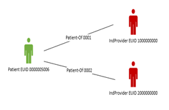
After the default MRG event policy processes the MRG event, the result is illustrated in Figure 6-7. The Patient EUID 0000005005 is merged to the Patient EUID 0000005006. The Patient EUID 0000005005 is the merged entity and the Patient EUID 0000005006 is the surviving entity. The following are the steps performed by the default MRG event policy:
Deactivate the merged entity.
Deactivate Patient EUID 0000005005.
Deactivate the relationship associated with the merged entity.
Deactivate the merged relationship Patient-Of 0001.
Replicate the merged relationship to the surviving entity.
Replicate the merged relationship Patient-Of 0001 between the surviving Patient EUID 0000005006 and IndProvider 2000000000.
Record the merge information in the relationship merge table to keep track of the merge.
Each of two MPI entities from one MPI domain has the different relationship of the different relationship type with the different entities from other MPI domain. Figure 6-8 illustrates a sample MRG use case D diagram.
Figure 6-9 Merge Result of Sample MRG Use Case D
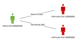
After the default MRG event policy processes the MRG event, the result is illustrated in Figure 6-9. The Patient EUID 0000005005 is merged to the Patient EUID 0000005006. The Patient EUID 0000005005 is the merged entity and the Patient EUID 0000005006 is the surviving entity. The following are the steps performed by the default MRG event policy:
Deactivate the merged entity.
Deactivate Patient EUID 0000005005.
Deactivate the relationship associated with the merged entity.
Deactivate the merged relationship Patient-Of 0001.
Create a new relationship which to the surviving entity.
Replicate the merged relationship Patient-Of 0001 between the surviving Patient EUID 0000005006 and IndProvider 1000000000.
Record the merge information in the relationship merge table to keep track of the merge.
This relationship event policy defines and implements the default business and processing logic for processing UNMRG event.
Each MRG use case has its corresponding UNMRG use case logically. The UNMRG process is a reverse process of the MRG to roll back the changes resulted from the MRG.
The processing of the above use cases is about changing source entity of a relationship. The same logic can apply to the changing of target entity of a relationship and multiple relationships.
This relationship event policy defines and implements the default business and processing logic for processing ADD event. The policy performs the following steps to process ADD event:
Validate the entity
Look up the entity
Update the attributes of the entity based on the entity type metadata if the entity exists in the relationship management database
Create a new entity if the entity does not exist in the relationship management database
Look up the Ruleset registry
Execute the ruleset to create a relationship if the ruleset is found for the entity
Process completes if the ruleset is not found
By default, no ruleset is configured in the ruleset registry. Therefore, the default Add event policy creates or updates the entity in the relationship management database.
The relationship management MPI agent is used for subscribing to the OHMPI JMS outbound topic and receiving all the OHMPI events from the OHMPI applications. The relationship management MPI agent transforms the XML event into the relationship management message, and sends it to the relationship management service by invoking the relationship management synchronization REST API. The relationship management MPI agent can filter out the unwanted events to the relationship management service. The filter is configurable.
In order for the relationship management to synchronize the MPI events from the MPI applications, several applications are required to be configured and deployed. Figure 6-10 illustrates the required software and applications.
Figure 6-10 Deployment Architecture of OHMPI and MPI Agent, and the Relationship Management
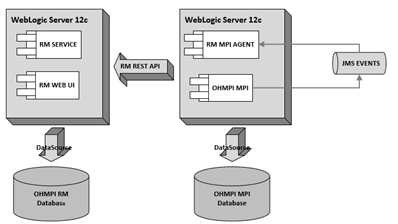
Figure 6-11 illustrates the process of the OHMPI JMS outbound events, the relationship management MPI agent, and includes the triggering process of the default or custom relationship event policy.
Figure 6-11 Relationship Event Policy Processing Dataflow
To create a relationship management MPI agent application, perform the following steps:
Create the relationship management MPI application. For information, see Chapter 2, "Creating the Relationship Management Project".
Create and build the relationship management MPI agent application. For information, see Section 6.3.2.1, "Creating and Building the Relationship Management MPI Agent".
Configure the relationship management MPI agent application. For information, see Section 6.3.2.2, "Configuring the Relationship Management MPI Agent".
Deploy the relationship management MPI agent application. For information, see Section 6.3.2.3, "Deploying the Relationship Management MPI Agent".
In the Projects window, right-click on the RM project and select Create MPI Agent.
The Create MPI Agent dialog box appears.
Enter values for the following:
MPI application name
Base Url
Wallet File Path
RM Date Format
MPI Date Format
MPI Events
Click Create.
The relationship management wizard creates the MPI agent and builds the EAR file of the MPI agent in the dist folder of the project. The file name is <MPI application name>-ohmpi-rm-agent-1.0.0.ear.
To create a different MPI agent, repeat steps 1 through 3.
To open the existing relationship management project:
From the NetBeans IDE, click File and then select Open Project.
In the Open Project panel, browse to the path where you have created the relationship management project.
Select the relationship management project and click Open Project.
In the Projects window, expand the relationship management project > configuration node > Agent node.
Right-click the rm_agent.properties file and select Edit.
The MPI agent properties appear in the right panel.
Edit the following properties in the rm_agent.properties file:
Edit the base URL (relationship.management.base.url) of the relationship management REST APIs
Edit the wallet file path (relationship.management.wallet.file) of the relationship management MPI agent
Edit the relationship management supported MPI events (relationship.management.events)
You can define multiple events delimited by a comma. The default events are ADD, MRG, and UNMRG. You can add UPD, DEA, and REA events. The relationship management provides out-of-box default event policies for processing ADD, MRG, and UNMRG events, but does not provide any default event policies for UPD, DEA, and REA events.
Edit the date format (relationship.management.date.format) of the relationship management service
Edit the date format (relationship.management.mpi.date.format) of the MPI domain application
Edit the MPI domain application name (relationship.management.mpi.application.name)
To configure the RM MPI agent:
Open the file that you want to modify.
From the Configuration\agent folder, you can modify the following file:
rm_agent.properties
From the Configuration\agent\META-INF folder, you can modify the following files:
application.xml
web.xml
weblogic.xml
Edit the file, as required.
Save the file.
The relationship management MPI agent is always deployed to the same WebLogic Server domain where the OHMMPI application runs. Each OHMPI application requires its own specific MPI agent. To deploy the MPI agent, you must first configure the OHMPI outbound JMS topic and deploy the OHMPI application, and then perform the following steps:
Create and install the MPI agent wallet file. For information, see Section 6.3.2.3.1, "Creating the RM MPI Agent Wallet Files".
Deploy and run the MPI agent application. For information, see Section 6.3.2.3.2, "Deploying and Running the MPI Agent Application on Oracle WebLogic Server".
Note:
Make sure that JVM 1.7.0_67 or higher version is set in the system execution path.Go to the relationship management project folder on the command console.
Execute the following command in the wallet creation utility:
run generate-wallet.bat/generate-wallet.sh [userName] [password] [walletpwd]
where,
username: Username for the RM agent connecting or executing to the RM APIs
password: Password for the RM connecting or executing to the RM APIs
walletpwd: Wallet password for securing the wallet content
The ohmpiRMWallet folder is created.
Copy the ohmpiRMWallet folder to the MPI domain config folder of your WebLogic Server.
Expand your relationship management project in the Projects windows and open the rm_agent.properties file.
Edit relationship.management.wallet.file in the rm_agent.properties file and set it to be ./config/ohmpiRMWallet.
Build and deploy the RM MPI agent. For information, see Section 6.3.2, "Creating the Relationship Management MPI Agent".
On the left panel of the WebLogic Server Administration Console, under Domain Structure, select Environment > Deployments.
The Summary of Deployments panel appears.
Click Install.
The Summary of Deployments panel with a Deployments table containing a list of EAR files appears.
Locate your application EAR and click Next.
The Install Application Assistant section appears in the right panel.
Locate the deployment file you want to install and prepare for deployment.
Tip:
Select the file path that represent the application root directory, archive file, exploded archive directory, or application module descriptor that you want to install. You can also enter the path of the application directory or file in the Path field.Note:
Only valid file paths are displayed. If you cannot find your deployment files, upload your file(s) and/or confirm that your application contains the required deployment descriptors.Click Next.
Note:
When deploying an MPI EAR file through the WebLogic Administrator Console, under Security, make sure that you select the DD Only option.Click Finish.
This section explains how to customize the relationship event policy. To customize the relationship event policy, you must implement the Event Policy interface using groovy script, and load it to the relationship management task registry using the reserved task names for the relationship event policies.
AddEventPolicy is the reserved task name for the custom relationship ADD event policy
MrgEventPolicy is the reserved task name for custom relationship MRG event policy
UnmrgEventPolicy is the reserved task name for custom relationship UNMRG event policy
To customize the relationship event policy:
Determine which event needs to be customized.
Define the custom event business and processing logic.
Implement the custom relationship event policy interface in groovy script.
You create the event policy interface implementation file name with the .groovy extension file name. For example, CustomAddEventPolicyImpl.groovy.
Load the custom relationship event policy interface implementation either using the relationship management REST API or the relationship management data manager by assigning the reserved task name for the relationship event policy.
To use the relationship management REST API:
Register the custom relationship event policy using the management REST API:
POST /management/tasks/{task}
For example,
POST /management/tasks/MrgEventPolicy
{"name": "MrgEventPolicy"}
Upload the custom relationship update policy script groovy file using the management REST API:
PUT /management/tasks/{task}files
For example,
PUT/management/tasks/MrgEventPolicy/files
CustomAddEventPolicyImpl.groovy
package oracle.hsgbu.ohmpi.rm.policy;
/**
* EventPolicy Interface
* @author <author_name>
*/
public interface EventPolicy {
   /* The reserved task name for custom relationship ADD event policy*/
   public static final String ADD_EVENT_POLICY = "AddEventPolicy";
   /* The reserved task name for custom relationship UPD event policy*/
   public static final String UPD_EVENT_POLICY = "UpdEventPolicy";
   /* The reserved task name for custom relationship MRG event policy*/
   public static final String MRG_EVENT_POLICY = "MrgEventPolicy";
   /* The reserved task name for custom relationship UNMRG event policy*/
   public static final String UNMRG_EVENT_POLICY = "UnmrgEventPolicy";
   /* The reserved task name for custom relationship DEA event policy*/
   public static final String DEA_EVENT_POLICY = "DeaEventPolicy";
   /* The reserved task name for custom relationship REA event policy*/
   public static final String REA_EVENT_POLICY = "ReaEventPolicy";
   /**
   * callback method to execute the event policy
   * @param context EventPolicy context
   * @throws EventPolicyException
   */
   void apply(EventPolicyContext context)
      throws EventPolicyException;
}