6 VSM 7 Ethernet (IP) Data Path Connectivity
Unlike VSM 6, customer networks are not connected directly to the VSM 7 server nodes. Instead, the customer network uplinks connect to the two ES1-24 switches, which in turn connect to the Ethernet ports on the two VSM 7 server nodes.
VSM 7 Ethernet (IP) Port Assignments
Figure 6-1 shows the IP Ethernet ports on each VSM 7 node.
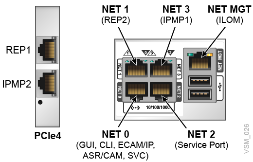
The network ports (NET0, NET1, NET2) are connected to various networks through the two ES1-24 switches:
-
Port 0 (NET0) is for user interface connections (CLI, GUI, ECAM over IP).
-
Port 1 (NET1) connects to the Oracle Switch ES1-24 10GbE Ethernet switches
-
Port 2 (NET2) is a dedicated maintenance port reserved for direct connection by Services. Port 1 on each switch is dedicated to field maintenance for Port 2 (NET2); Switch 1 goes to Node 1 and Switch 2 goes to Node 2.
Port 3 (NET3) is not connected to the network switches. It is connected directly to NET3 on the other server node.
The Twinville HBA ports PCIe4 are connected to their respective networks through the ES1-24 switches:
-
Port 4 is used for replication over IP (RoIP).
-
Port 5 is used for IPMP connections
Network Switch Port Assignments
The two Oracle ES1-24 network switches are mounted at the top of the rack to aggregate or fan out network connections from the servers to the customer's network environment.
Specifically, the switches provide:
-
Redundant connections for all network connections except the ILOM ports.
-
Aggregation and fan-out of the four RoIP connections from the two VTSS servers to four copper or four optical RoIP connections that may be connected to the customer's network environment.
-
Aggregation of the ILOM and Service port connections from the servers to a pair of single, redundant ports, one on each switch.
-
Aggregation of the ECAM, VSM GUI, ASR/CAM networks from the two servers to a pair of single, redundant ports, one on each switch.
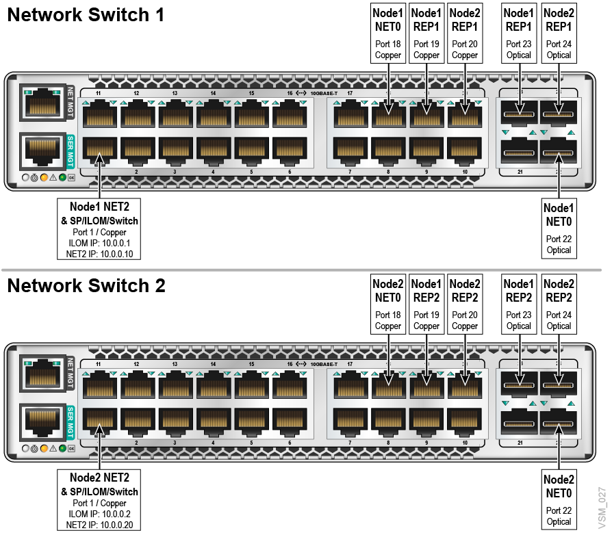
Figure 6-2 shows the port assignments from the servers to the two ES1-24 Ethernet switches.
A port connection must use all copper or all optical but not both on a single switch (for example, NET0, REP1, REP2).
Customer networks must be connected to the ES1-24 switches and may not be connected directly to the VSM 7 server ports.
Customer Network Integration
The ES1-24 switches in the VSM 7 rack represent a major change from VSM 6, where customer network connections were plugged directly into the servers. Now, with VSM 7, the customer network is instead plugged into the switches, and the switches in turn are plugged into the servers.
To access NET0 interfaces, the customer connects to either port 18 (if copper/RJ45) or port 22 (if optical) on both Switch-1 (Node 1 interfaces) and Switch-2 (Node 2 interfaces).
-
For Net0 traffic on Node 1, an uplink is connected from the customer infrastructure to port 18 (if copper/RJ45) or port 22 (if optic) to switch 1
-
For Net0 traffic on Node 2, an uplink is connected from the customer infrastructure to port 18 (if copper/RJ45) or port 22 (if optic) to switch 2
Replication traffic warrants two 10Gb uplinks for REPx traffic (20Gb total). REP1 traffic goes through Switch 1 and REP2 traffic goes through Switch 2. To provide adequate bandwidth to nodes, uplinks on switches for REPx traffic are assumed to be on the same subnet and configured in port-channel from the customer infrastructure.
-
For REP1 traffic to both Node 1 and Node 2, uplinks are connected from the customer infrastructure to ports 19 and 20 (if copper/RJ45) or ports 23 and 24 (if optic) to switch 1.
-
For REP2 traffic to both Node 1 and Node 2, uplinks are connected from the customer infrastructure to ports 19 and 20 (if copper/RJ45) or ports 23 and 24 (if optic) to switch 2.