12 Controlling the Reporting of Monitored Traffic
This chapter describes how the reporting of monitored traffic can be fine optimized to meet your information requirements. This includes the specification of the cookie technologies used within your network environment, use of named web server and client groups, as well as a number of advanced facilities, such as rule ordering and data retention policies.
12.1 Viewing a Traffic Summary
You can open an overview of the monitored network traffic by selecting System, then Status, and then Data processing. A list of the processing systems within your RUEI deployment is displayed. An example is shown in Figure 12-1.
Figure 12-1 Data Processing Status Window
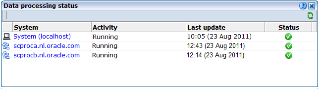
Description of ''Figure 12-1 Data Processing Status Window''
Click the required system to view information about hits, pages, and session processing, as well as the system load. An example is shown in Figure 12-2.
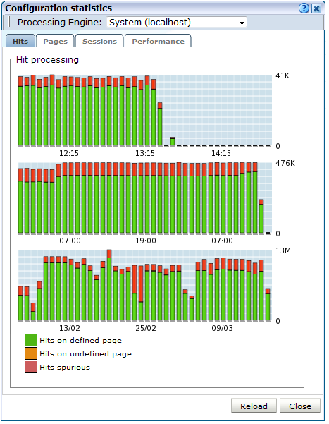
Note the Available resource usage (%) item on the Performance tab indicates the current processing level. If this approaches 100%, it means a lag in the processing of data is starting to occur, and it is no longer possible to process data in real time.
Be aware that because this facility is based on application logic, non-application traffic (such as suites, services, and SSOs), are not represented in the displayed reports.
Important:
In order for RUEI to correctly report on monitored traffic, it is strongly recommended that you regularly review this traffic summary. If necessary, review the RUEI configuration accordingly. For example, add additional cookie technologies. In addition, if the system is unable to track sessions, proper tracking of user flows will also not be available because user flow reporting requires session tracking.12.2 Specifying the Session Tracking Mechanism
In order to accurately monitor your web environment, RUEI needs to know and understand the cookie technology or other session-tracking mechanism your web site is using. This will either be a standard technology (such as ASP or ColdFusion), or a custom implementation. In the case of the latter, you will need to provide the system with information about it.
Cookie technologies can be specified for specific applications and suites, as well as for global session tracking. Note that application-specific session tracking definitions take precedence over global session tracking settings. You can define a maximum of nine application-specific cookie technologies and nine global cookie technologies for use when monitoring.
Specifying Application-Specific Cookie Technologies
Do the following:
-
Select Configuration, then Applications or Suites, and select the required application. The application overview appears. Click the Advanced tab, and then the Session tracking tab.
-
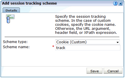
Click Add new session tracking mechanism or an existing definition. A dialog similar to the one shown in Figure 12-3 appears.
Figure 12-3 Add Session Tracking Scheme Dialog
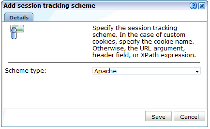
Description of ''Figure 12-3 Add Session Tracking Scheme Dialog''
-
Select the cookie technology used in your web environment from the Scheme type menu. If you are using a non-standard technology, select "(custom)" and specify the name of the cookie used by your organization. You can specify wildcard characters (*) as part of the cookie name. Note that cookie names are case sensitive.
The "XPath (custom)" option specifies that session tracking is based on an XPath expression applied to the request or response. For more information on the use of XPath expressions, see Appendix F, "Working with XPath Queries". The "Header (custom)" option specifies that session tracking is based on a specified request or response header.
If you select "(URL argument)", you are required to specify the name of the URL argument used by your organization. The use of URL arguments in session tracking is explained in Appendix B, "Cookie Structures".
When ready, click Save. Any changes you make are applied after a short interval (typically, 5 - 10 minutes), and are then visible within the Reporter system shortly after this.
Specifying Global Session Tracking Mechanisms
Do the following:
-
Select Configuration, then Applications, and then Global session tracking. Note that this option is only available to Administrators. The currently defined global settings are displayed. An example is shown in Figure 12-4.
Figure 12-4 Global Session Tracking Window
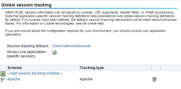
Description of ''Figure 12-4 Global Session Tracking Window''
-
Select the option for Always use application specific sessions. If selected sessions are always handled as application-specific. If two hits are identified as different applications, they never become part of the same session. When unchecked, sessions are handled as application specific only when there is a match on a configured application-specific cookie.
-
Click Add session tracking scheme or an existing definition. The procedure is the same as described above.
-
The use of the Session tracking fallback setting is described in Section 12.2.2, "Specifying the Fallback Session Tracking Mechanism".
When multiple configured cookies are found in the same hit, RUEI merges all hits with the multiple cookie values into a single user session. For example, consider the situation in which three hits have following cookie values:
hit1: CookieA=123;
hit2: CookieB=321;CookieA=123;
hit3: CookieB=321;
In this case, all three hits will be regarded as belonging to the same user session.
It is recommended that you configure cookie definitions on an application-specific basis, unless you want multiple applications to be reported across the same session.
12.2.1 Implementing JavaScript Cookie Generation
As mentioned earlier, session tracking can be based on cookies. However, in certain circumstances, a cookie may not be suitable or available. For example, consider the following situations:
-
The cookie changes with every hit (for instance, this is the case with
ObSSOCookie). -
The path set within the cookie only covers part of the application.
-
The privacy policies configured on the web server disable the use of cookies.
If no suitable cookie is available for session tracking, it is recommended that you implement a client-side cookie mechanism using JavaScript.
Configuring a Client-Side Cookie Mechanism
Do the following:
-
Add code similar to the following to the appropriate login page:
<SCRIPT
LANGUAGE="JavaScript">if(document.cookie.indexOf('track=')==-1){document.cookie
='track='+parseInt(Math.random()*2147418112)+new
Date().getTime()+';path=/;domain='+document.location.host.substring(
document.location.host.lastIndexOf('.',
document.location.host.lastIndexOf('.') - 1)) ;}</SCRIPT>
Note that the above code is for informational purposes only. You may need to modify it to meet your specific requirements.
-
Select Configuration, then Applications, and then Session tracking. Click Add new cookie. The dialog shown in Figure 12-5 appears.
Figure 12-5 Add Session Tracking Scheme Dialog
Description of ''Figure 12-5 Add Session Tracking Scheme Dialog''
-
Select the cookie technology (custom) from the Scheme type menu, and specify the appropriate cookie name. In the above JavaScript code, this is
track. Note that the name should match that specified in the login page JavaScript code, and should only contain alphanumeric characters. In addition, it is recommended that the cookie name is restricted to no more than 10 characters in order to minimize header sizes. When ready, click Save.
Verifying the Cookie Configuration
To verify that your cookie configuration is being tracked correctly, do the following:
-
Clear all cookies in the browser.
-
(Re)login to the monitored application.
-
Perform a number of page views.
-
Logout out of the monitored application.
-
Wait for at least 10 minutes.
-
Open the RUEI Reporter environment, and select Browse data, open the All sessions group, select Session diagnostics, and locate the recorded session (by user ID or time). You can filter on applications.
-
Open the session and verify that there where more page views than just the login page. This verifies that the session ID is preserved after the login.
12.2.2 Specifying the Fallback Session Tracking Mechanism
If you do not specify a cookie technology, then (by default) a combination of the client network and client browser is used to track sessions. However, in the event that this is not suitable for your environment, the client IP address can be used as an alternative tracking mechanism.
To specify the fallback session tracking mechanism, do the following:
-
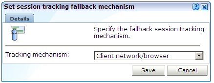
Select Configuration, then Applications, and then Session tracking. The currently defined cookie settings are displayed. Click the currently defined session tracking fallback mechanism. The dialog shown in Figure 12-6 appears.
Figure 12-6 Set Session Tracking Fallback Dialog
Description of ''Figure 12-6 Set Session Tracking Fallback Dialog''
-
Use the Tracking mechanism menu to specify if a client network and browser combination should be used (the default), or the client IP address.
When ready, click Save. Any change you make takes effect immediately.
Which Fallback Session Tracking Mechanism Should be Selected?
When considering which fallback mechanism to use, a general rule is that external-facing applications should use the default network/browser combination, while internal-facing applications should use client IP address. In the case of multiple users behind the same proxy server, the use of the default fallback mechanism is recommended. However, be aware this will result in all such users being recorded in one single session. The use of the client IP address mechanism is generally recommended in the following circumstances:
-
All users have a unique IP address. Note that for each application, you can specify if the client IP address should be retrieved from the TCP packet or a specific HTTP request header. This is described in Appendix Q, "Monitoring NATed Traffic".
-
The organization enforces the use of a normalized browser. That is, a standard browser (such as Internet Explorer or Mozilla Firefox), with a standard version and plug-ins.
-
Some (or all) of the monitored applications are partially implemented in Java. Oracle E-Business Suite (EBS) is an example of such an application architecture. For these applications, the use of the client IP address mechanism prevents both Java and client requests appearing in the same reported session.
Important:
The accurate specification of the cookie technologies used within your web site is strongly recommended to ensure the accurate reporting of your network traffic.In addition, you should that the cookie specified to track visitor sessions is not blinded. If it is, session creation based on the cookie will fail.
12.3 Defining Named Web Server Groups
You can use the Named servers facility to obtain more detailed insight into server usage within your monitored web sites. This facility allows you to assign ranges of server IP addresses to a web server group, and to individual web servers. For example, a server group could be a department or data center, and the server name refers to specific web servers within that group. In this way, you can easily identify the location of specific web servers when problems (such as failed pages) occurred. The Named server facility is only available to users with Full IT user access (see Table 14-2).
The web server information collected during monitoring can be viewed in the Data Browser via the All pages, Key pages, All functions, Failed functions groups, Failed URLs, Failed pages, and Slow URLs groups. The server IP identifies the specified IP addresses, and the server group refers to the group name. By zooming into a server group, you can view the individual web server names that comprise the group. Zoom in again, and you can view the individual IP addresses assigned to that web server.
Sources for Named Server Identification
When reporting named servers, the server's IP address is, by default, fetched from the IP packet. However, when the web server is placed in front of a NAT device, it may be more useful for the IP address to be obtained from a specific HTTP header, cookie, or other item. For this reason, you can specify a hierarchy of sources from which it should be obtained. Similar source schemes can also be specified for group and server names. Note that you can also define fallback identification that should be used when these schemes fail to yield a value.
12.3.1 Defining Named Server Identification Sources
To define how your web servers should be identified and reported, do the following:
-
Select Configuration, then General, and then Named servers. Select one of the following options:
-
IP address sources: use this option to specify the sources from which server IP addresses should be obtained.
-
Named sources: use this option to specify the sources from which server names should be obtained.
-
Group sources: use this option to specify the sources from which server group names should be obtained.
-
Identification fallback: use this option to specify the IP address ranges, groups, and names that should be used for server identification when they cannot be obtained from their defined sources. The use of this option is described in Section 12.2.2, "Specifying the Fallback Session Tracking Mechanism".
-
-
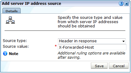
Click Add new source. A dialog similar to the one shown in Figure 12-7 appears.
Figure 12-7 Add Server IP Address Source Dialog
Description of ''Figure 12-7 Add Server IP Address Source Dialog''
-
Use the Source type and Source value fields to specify the identification scheme that should be used for the selected item. The available options are explained in Table 12-1. When ready, click Save.
Table 12-1 Identification Options
Option Description Header in request
The identification item should be taken from a specified request header.
Header in response
The identification item should be taken from a specified response header.
Cookie
The identification item should be taken from a specified cookie element.
SSL Client certificate name
The identification item should be taken from the SSL client certificate. This option is not available for IP addresses.
Literal value
Specifies a literal value for the identification item. This option is not available for IP addresses.
-
Once created, you can use the ruling facility to specify additional matching rules that should be used to refine the newly created definition. This is described in Section 7.3.5, "Using the Ruling Facility".
-
It is important to understand that the defined sources for a server's identification are evaluated in the order in which they appear in the list. If necessary, you can use the Move up and Move down options within an item's context menu to modify its position within the list.
12.3.2 Defining the Server Identification Fallback Scheme
You can define a server identification scheme that should be used if information about a server cannot be obtained from its specified sources. This is referred to as server identification fallback. To define a identification fallback scheme, do the following:
-
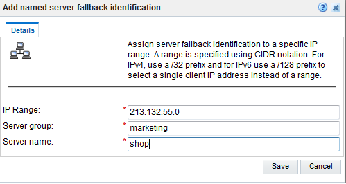
Select Configuration, then General, then Named servers, and then Identification fallback. Click Add new server. The dialog shown in Figure 12-8 appears.
Figure 12-8 Add Named Server Fallback Identification Dialog
Description of ''Figure 12-8 Add Named Server Fallback Identification Dialog''
-
Specify a range of IP addresses (or a specific IP address) within a netmask, and the associated web server and group names. When ready, click Save.
Important:
The specified IP address/ CIDR prefix length combination must be unique. CIDR with prefix length equals to 0 is not acceptable. In addition, if duplicate IP addresses with different netmasks are specified, the more specific one is used for reporting purposes.Uploading a List of Fallback Identifications
Optionally, you can click Upload to merge a list of fallback identification definitions with those that are currently defined. The file must contain only one entry per line, and the information for each server (as shown in Figure 12-8) must be tab-separated. Note that any definition in the merged file for an already defined server identification overwrites its existing definition.
12.4 Defining Named Client Groups
In some instances, you want to be able to enhance the information associated with visitor IP addresses. This is especially useful when monitoring Intranet traffic and you want to be able to use your own client classification.
To use this facility, do the following:
-
Select Configuration, then General, and then Named clients. The currently defined named servers are listed. Click Add. This option is only available to users with IT Full level access. The dialog shown in Figure 12-9 appears.
-
Use the fields within the dialog to specify a range of IPv4 or IPv6 addresses or a specific address within a netmask, the client, and their associated group (for example, company department). When ready, click Save.
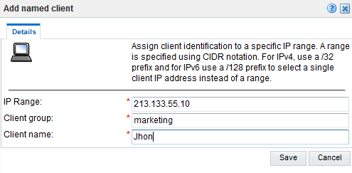
The specified IP address combination must be unique. In addition, if duplicate IP addresses with different netmasks are specified, the more specific one is used for reporting purposes.
12.4.1 Uploading a List of Named Clients
Optionally, you can click Upload to merge a list of named clients with those that are currently defined. The file must contain only one entry per line, and the information for each client (shown in Figure 12-9) must be tab-separated. Note that any definition in the merged file for an already defined named client overwrites its existing definition.
Any changes made to your defined named client groups are applied after a short interval (typically, 5-10 minutes), and are then visible within the Reporter system shortly after this.
12.5 Controlling Slow URL and Function Call Reporting
The Slow URLs and Slow functions data groups described in Table 3-6 report on the slowest 5000 objects per 5-minute period detected by the system, based on the function call's end-to-end time. Note that, by default, objects and function calls must have an end-to-end time of at least 2000 milliseconds to be reported in their respective views. However, this threshold can be modified in order to meet your reporting requirements.
Modifying the Slow Reporting Threshold
Do the following:
-
Select Configuration, then General, then Advanced settings, then URL handling, and then Slow URL and function call threshold. The dialog shown in Figure 12-10 appears.
Figure 12-10 Edit Slow URL and Function Call Threshold Dialog Box
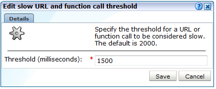
Description of ''Figure 12-10 Edit Slow URL and Function Call Threshold Dialog Box''
-
Specify (in milliseconds) an object's or function's call required end-to-time before it is considered slow. When ready, click Save.
12.6 Ignoring Failed URL Hits
Hit failures are recorded in the failed URL group. Because hit failures can occur for a wide variety of reasons, you can control what is recorded. For example, it is unlikely that you want incidents related to remote robot searches to be recorded. Do the following:
-
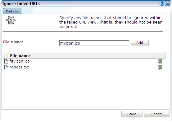
Select Configuration, then General, then Advanced settings, then URL handling, and then Ignore failed URLs. Note that this option is only available to Administrators. The dialog shown in Figure 12-11 appears.
-
Specify any file names that should be ignored within the failed URL view. That is, they should not be seen as errors. Note that any directory information within file name definitions are ignored, and the defined files are also removed from the listed object URLs. Click Add to define a new file name that should be ignored. Click the Remove icon to the right of a defined file name to delete it from the list of files to be ignored.
Upon installation, two default files,
robots.txtandfavicon.ico, are automatically configured. When ready, Click Save. Any changes to this setting are applied after 10 minutes. A short period after this time, the changes you have specified are visible in the Reporter interface.
12.7 Filtering Arguments in the Page URL Dimension
You can control whether you want all, some, or no URL arguments recorded within the lowest level page URL dimension. Do the following:
-
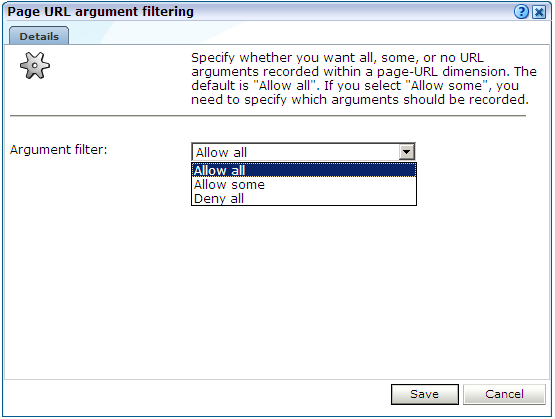
Select Configuration, then General, then Advanced settings, then Page URL handling, and then Page URL argument filtering. Note that this option is only available to Administrators. The dialog shown in Figure 12-12 appears.
Figure 12-12 Page URL Argument Filtering
Description of ''Figure 12-12 Page URL Argument Filtering''
-
Use the Argument filter menu to select the appropriate filter. The default is ”allow-all”. That is, record all arguments. When ready, click Next.
-
If you selected the "allow-some" filter, the next dialog requires you specify which arguments should be recorded. Separate multiple arguments with an ampersand (&) symbol. When ready, click Next.
The new setting is applied after 10 minutes. Shortly after this time, the changes you have specified are visible in the Reporter interface.
Note:
It is recommended that you make use of this facility if session or other random arguments are included in your page URLs. Otherwise, the content of page-based views (such as all pages or failed URLs) can become very large.12.8 Controlling Session Reporting
Within RUEI, session information is reported within the All sessions group. Here, information about a visitor session is available appropriately five minutes after the start of a session. By default, a visitor session is considered terminated if the visitor has been inactive for longer than the defined session idle time (by default, 60 minutes).
In order to optimize the reporting of sessions, the Session idle time advanced setting is available to specify the period (in minutes) of inactivity after which a visitor session is regarded as terminated. The default is 60 minutes.
Important:
Because of the impact this setting can have on the performance of your installation, as well as the accuracy of the reported data, it is strongly recommended that you only change it under guidance from Customer Support.In order to specify the idle time that should used when reporting sessions, do the following:
-
Select Configuration, then General, then Advanced settings, then Session processing, and then Session idle time. The dialog shown in Figure 12-13 appears.
Figure 12-13 Change Session Reporting Dialog
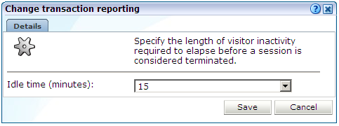
Description of ''Figure 12-13 Change Session Reporting Dialog''
-
Specify, in minutes, the period of visitor inactivity after which the session should be regarded as terminated. The default is 60 minutes. When ready, click Save.
Any change you make to this setting takes effect within five minutes.
12.9 Controlling Rule Ordering Within RUEI
By default, the order in which application, SSO profile, suite, and service filters are matched within RUEI is determined by the level of detail specified in the definition. That is, the definitions with the most information specified for them are applied first. However, sometimes you may want to modify the order in which filters are applied.
For example, you want to monitor network traffic for the domain "shop.oracle.com". You have defined two applications: one for the domain "shop*", and one for the domain "*oracle*. Because the string "*oracle*" is longer than the string "shop*", it is applied first. However, you want page identification for the "shop*" domain to take priority. You can use the rule ordering facility to override the default rule matching order, and specify the order in which pages for the required domains should be applied.
Note:
It is recommended you use the default rule ordering, and that you define your applications, SSO profiles, suites, and services with sufficient information for them to be mutually exclusive.To use the rule ordering facility, do the following:
-
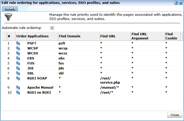
Click the Configuration tab, select the Configuration menu option, and then the option Edit ruling orders. Note this option is only available to users with Full IT access permissions. The dialog shown in Figure 12-14 appears.
-
Use the Automatic rule ordering check box to specify whether the rule ordering is automatically derived from the currently defined applications, SSO profiles, suites, and services. As explained earlier, by default, the definitions with the most information specified for them are applied first. This is check box is automatically unchecked if you use the order controls to specify the order in which the rules should be applied. If you re-check it, the filter ordering is automatically reset to the default.
To change the order, click the up/down icon in the Order column and specify the New priority order you require in the pop up screen.
Note any changes you make are immediately put into effect. When ready, click Close.
Important:
Be aware that if you modify the default rule ordering, and then define a new application, SSO profile, suite, or service, its associated filter is immediately placed at the bottom of the current rule ordering. Therefore, you should always review the rule ordering after the creation of new filters.
12.10 Specifying Data Retention Policies
The level of detail of RUEI reporting depends on the measured traffic volume and the amount of disk space available. In order to cope with huge traffic volumes, data is processed into data types (All Pages, All sessions, and Slow URLs) for specific reporting goals and is per data type aggregated over time.
The time based aggregation method is called Data Aggregation. The following data aggregation levels are available:
-
Instance: (default 8 days)
-
5-minute: (default 15 days)
-
Hourly: (default 32 days)
-
Daily: (default 90 days)
-
Monthly: (default 60 months)
Data retention is about balancing between the amount of available disk space and the level of reporting details available over time. For example, setting Instance data aggregation for Applications from 8 to 40 days will mean that for 40 days, high level application detail will be available for reporting (probably costing a lot of disk space). In addition, setting Monthly aggregation from 60 to 90 months will allow (lower detail) trend reporting, but with also the extra cost of disk space.
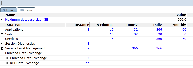
The reported data retention policy advanced settings screen consist of two tabs Settings and DB Usage. The Settings tab is shown in Figure 12-15:
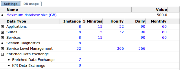
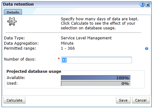
Policies can be specified per data type group and by clicking the + sign on a finer grained level for each data type. Data aggregation levels can be configured per data type group or data type. Click a number in the settings tab to open data retention dialog, as shown in Figure 12-16:
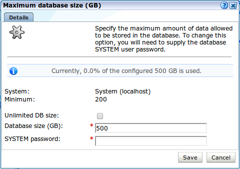
Maximum database size can be configured per database in the settings tab. In a stand-alone setup only one database can be configured. But in a scaled setup (Reporter with multiple processing nodes), the maximum size per database can be specified. Click Maximum database size (GB) to open the dialog shown in Figure 12-17:
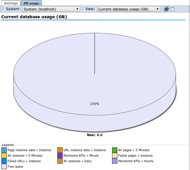
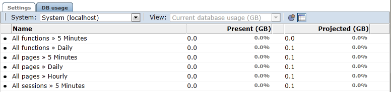
The DB usage tab shows the current and projected disk space used per database (Reported Database or Databases on the processing nodes). Use the system drop down to select the node and the view drop down to alternate between current and projected database usage. Click the table icon to switch from pie chart to table, as shown in Figure 12-18.
Oracle recommends that you regularly check current and projected database usage, particularly with a new deployment. The more data is measured, the more accurate the projections will be. Note that when the RUEI configuration is changed, for example by adding an new application, or changes are made to an existing application, caution must be taken to monitor the effect on the database usage.
12.10.1 Defining Reporter Retention Policies
This procedure describes how to define the Reporter retention policies.
Note:
The following settings do not only configure the reporter data retention policy for the current data, but also control the time based collector data retention policy for the replay stores.-
Session Diagnostics (days) also controls the time based retention for Full session replay store.
-
The larger number set for Application/Failed URLs setting (days) or Application/Failed Pages setting (days) also controls the time based retention for Error page replay store.
For example, if Session Diagnostics (days) is set to 8 days, the Session Diagnostics data will contain up to 8 days worth of sessions and a maximum of 8 days of full session replay data.
For more information on the collector data retention policy see Section 13.9, "Defining Collector Data Retention Policies."
To specify the data retention policies used by the Reporter system, do the following:
-
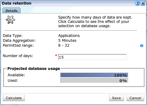
Select Configuration, then General, then Advanced settings, and then Reporter data retention policy. A screen similar to the one shown in Figure 12-19 appears.
-
Select the required setting.
A dialog similar to the one shown in Figure 12-20 appears.
-
Use the dialog's control to specify the retention policy for the selected option.
The projected database utilization (based on monitored traffic levels) is indicated. Information about disk space utilization is available within the dialog boxes for individual settings. Be aware that these estimates are based on the highest usage within the deployed processing systems. For example, if an item has a usage within the Reporter of 50%, and 20% within a Processing Engine, the higher value is used to report usage and availability.
For most settings, you can click Calculate to see the effect of your selection on database or disk space usage, as applicable.
When ready, click Save. Note that changes to disk space allocations take effect after approximately 10 minutes, while changes to database allocations only take effect after midnight.
-
Optionally, click the DB usage tab for an indication of the total database space (in gigabytes) currently used for an item, and the proportion this represents of the database's maximum permitted size. An example is shown in Figure 12-21.
Note:
It is recommended that if you want to increase the amount of data kept, you start with the low-level data retention setting and work towards the high-level data retention setting. If you want to decrease the amount of data kept, start with the high-level data retention setting, and work towards the low-level data retention setting.The minimum value for the monthly setting is determined by calculating the largest number of months that can be required to cover the specified number of days. For example, if 90 days is specified, the minimum value for the monthly setting is 4, since February, March, and April combined only cover 89 days. Conversely, when 3 months is specified, the maximum value for the daily setting is 89.
Note that configuration of Collector data retention policies is described in Section 13.9, "Defining Collector Data Retention Policies".
12.11 Controlling the Reporting of the Current Period
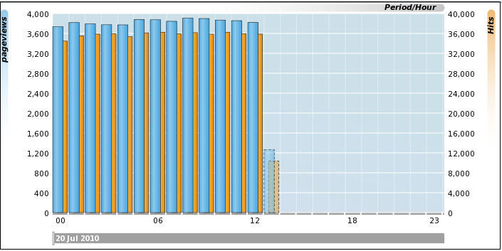
By default, information about the current (incomplete) period is always shown within selected periods that extend to the present time. In graphical visualizations, this is indicated with a dotted line. An example is shown in Figure 12-22.
Figure 12-22 Example of Incomplete Period Reporting
Description of ''Figure 12-22 Example of Incomplete Period Reporting''
Specifying When Incomplete Periods Should be Reported
To specify when incomplete periods should be reported, do the following:
-
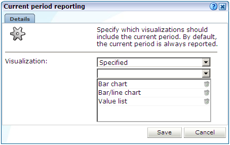
Select Configuration, then General, then Advanced settings, then Data visualization, and then Current period reporting. The dialog shown in Figure 12-23 appears.
Figure 12-23 Current Period Reporting Dialog
Description of ''Figure 12-23 Current Period Reporting Dialog''
-
Select the visualization scheme to be used when reporting the current period. The options shown in Table 12-2 are available.
Table 12-2 Visualization Options
Options Description Enabled
Specifies that all incomplete periods should be reported within all graphical visualizations, as well as value lists, reports, and exports. This is the default.
Disabled
Specifies that no incomplete period should ever be reported.
Specified
Specifies that incomplete periods should only be reported within the specific visualizations. Note that the "Value list" option covers not only value lists within the Data Browser, but also reports and exports.
When ready, click Save. Any change you make to this setting takes effect immediately.
12.12 Specifying KPI and SLA Reporting Precision
KPI and SLA values are reported to a certain level of precision. By default, this is two decimal places. However, you are free to modify this to reflect your reporting requirements. Do the following:
-
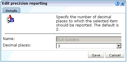
Select Configuration, then General, then Advanced settings, and then KPI and SLA precision reporting. Select the item whose reporting you want to modify. For example, SLA success. A dialog similar to the one shown in Figure 12-24 appears.
Figure 12-24 Edit Precision Reporting Dialog
Description of ''Figure 12-24 Edit Precision Reporting Dialog''
-
Specify the number of decimal places to which the selected item should be reported. When ready, click Save. Any change to these settings takes effect immediately.
12.13 Defining KPI Threshold Profiles
A threshold profile specifies the parameters to use when evaluating automatic targets for KPIs as described in Section 8.3.3, "Automatic and Fixed Targets".
RUEI includes a "System default" threshold profile. Create new profiles or edit this profile, but it is recommended that you do not delete it.
To define a KPI threshold profile:
-
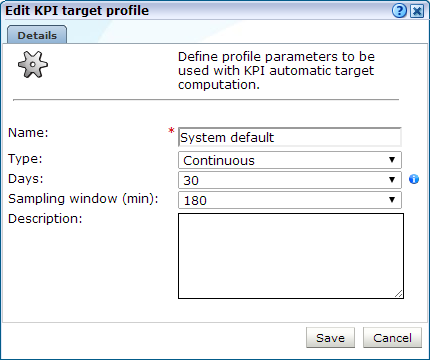
Select Configuration, then General, then Advanced settings, and then KPI threshold profiles. Select the item you want to modify or click Add.A dialog similar to the one shown in Figure 12-25 appears.
-
Specify the Name for the threshold profile.
-
Choose a Type from the following:
-
Continuous uses data from all the days available to the profile.
-
Same day of week uses data from the same day of the week that is available to the profile. For example, if there is data from two previous Mondays available, it will use that data to evaluate trends for a Monday.
-
Workweek allows you to specify working days for a week, creating two groups of days for trend evaluation. For example, data from Monday to Friday can be used to evaluate trends for any Monday to Friday. Similarly, data from Saturday and Sunday can be used to evaluate trends for weekend days.
-
-
Specify the number of Days or Weeks available to the profile. If you chose a Continuous type threshold profile, you specify the number of days of data that you want to make available for trend evaluation. For other threshold profiles, you specify the number of weeks of data that should be available. The maximum number of days or weeks for this setting is determined by the reporter data retention described in Section 12.10.1, "Defining Reporter Retention Policies".
Note:
Trend evaluation is more accurate if more data is available. If you choose a continuous type threshold profile and provide 30 days of data, the system has more data to work with than if you choose Same day of week type and provide 6 weeks of data because each day is matched, meaning there are only 6 matches for a particular day, for example Monday. -
Choose the Sampling window (min) for the threshold profile. This determines the responsiveness of the target with regard to changes in the data. For example a 90 minute window means that RUEI will look 45 minutes before and 45 minutes after the current 1 min period to determine the target minimum and maximum. A larger window means that short-lived variations in the data are less likely to affect the target over the period, while smaller window values means that the automatic target will fluctuate faster.
-
Enter a Description of the threshold profile and click Save.
Note:
You cannot delete a threshold profile while it is being used by a KPI.12.14 Setting System-Wide Preferences
As explained in Section 1.5, "Customizing Your Environment", users can customize the formatting settings used in their sessions. They can specify the characters used for the decimal point indicator and the thousand separator, and the date format that should be used. Administrators can also specify defaults for these settings on a system-wide basis by selecting System, then Maintenance, and then Formatting preferences.
12.15 Modifying Client Location Reporting
The client location information reported by RUEI is derived from a predefined table that specifies the geographical location associated with specific IP address and netmask combinations.
If the information held in this table does not meet your reporting requirements (that is, it is insufficient or incorrect), you can define exceptions to it that should be used when reporting. To define an IP address location exception, do the following:
-
Select Configuration, then General, and then IP address origins. Note that this option is only available to users with IT Full level access. The currently defined IP address location exceptions are listed. Click Add to define a new exception, or click an existing one to modify it. The dialog shown in Figure 12-26 appears.
Figure 12-26 Add IP Address Origin Dialog
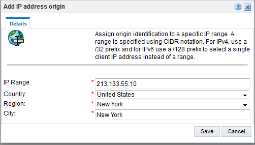
Description of ''Figure 12-26 Add IP Address Origin Dialog''
-
Use the fields within the dialog to specify an exception to the predefined IPv4 or IPv6 address locations. When ready, click Save.
The specified IP address combination must be unique. Note that if the client IP address in the monitored traffic matches multiple IP address/netmask combinations, the one with the smallest subnet range is used for reporting purposes.
12.15.1 Uploading a List of Named Locations
Optionally, you can click Upload to merge a list of exceptions with the currently defined IP address location exceptions. The uploaded file must contain one entry per line, and information fields must be tab-separated. Note that any definition in the file for an existing exception (that is, the same IP address/netmask combination) overwrites the existing exception. In addition, each of the fields in the uploaded file must meet the requirements shown in Table 12-3.
Table 12-3 Requirements for Uploaded File
| Field | Requirements |
|---|---|
|
IP address (in CIDR notation) |
Must be of valid IP format and CIDR prefix length equal to 0 is not acceptable |
|
Country code |
Must be a valid 2-character ISO 3166-1 country code (for example, "AL"). A complete list of supported country codes is available from the following location: https://en.wikipedia.org/wiki/ISO_3166-1 |
|
Region code |
This must be the code used to identify the region in the MaxMind database ( https://en.wikipedia.org/wiki/ISO_3166-2 |
|
City name |
There are no requirements for this field other than it cannot be blank. |
12.16 Controlling the Reporting of Objects as Pages
Within RUEI, forced objects are always be recorded as objects, and never as pages. This is regardless of the response time, or any errors that are reported for them. Table 12-4 shows the default file extensions used for forced objects.
Table 12-4 Default Forced Object File Extensions
| Extension | Extension | Extension |
|---|---|---|
.bmp |
.class |
.css |
|
|
.doc |
.gif |
.ico |
.jar |
.jpeg |
.jpg |
.js |
.mid |
.mpeg |
.mpg |
.png |
.ppt |
.properties |
.swf |
.tif |
.tiff |
.xls |
You can control whether objects with particular file extensions should be regarded as forced objects. Do the following:
-
Select Configuration, then General, then Advanced settings, then URL handling, and then Forced objects. The dialog shown in Figure 12-27 appears.
-
Specify the object file extension (without period) that should be treated as a forced object. When ready, click Add. The file extension is immediately added to the displayed list. Note that you can remove an object file extension from the list by clicking the Remove icon immediately to its right. When ready, click Save.
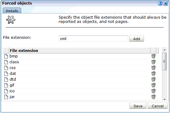
Note that any changes you make to the listed of defined forced object file extensions take effect immediately.
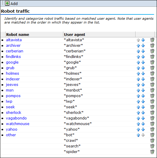
12.17 Controlling the Reporting of Robot Traffic
In order to more effectively monitor your network traffic, you might want to know how much of the traffic to your web site is associated with web crawlers (such as spiders and robots). In this case, you can control the matching of a robot's user agents to identify its origin. Note that robot traffic is reported via the client browser dimension. Do the following:
-
Select Configuration, then General, then Advanced Settings, and then Robot traffic. The currently defined robot identification schemes are shown. An example is shown in Figure 12-28.
-
Click Add. The dialog shown in Figure 12-29 appears.
Figure 12-29 Add Robot Identification Dialog
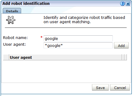
Description of ''Figure 12-29 Add Robot Identification Dialog''
-
Specify the name of the user agent whose traffic should be reported as robot traffic, and the name under which it should be reported. For each user agent, click Add. When ready, click Save. You are returned to the screen shown in Figure 12-28.
-
Use the Move up and Move down icons to control an item's order in the list. Note that user agents are matched in the order in which they appear in the list.
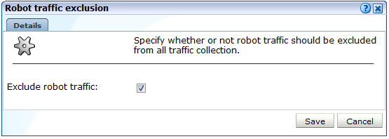
In addition to identifying robot traffic, you can also specify that it should be excluded from reported traffic. Do the following:
-
Select Configuration, then General, then Advanced settings, then Client-based traffic exclusion, and then click Robot traffic exclusion. The dialog shown in Figure 12-30 appears.
-
Use the Exclude robot traffic check box to specify whether the traffic matched to the specified user agents described above should be reported. By default, they are.
12.18 Excluding Client Traffic From Data Collection
In principle, all monitored traffic is reported. However, you can exclude traffic generated by specific clients from being collected. This is useful when, for example, large amounts of traffic is being reported from internal users. In addition, as described in Section 12.17, "Controlling the Reporting of Robot Traffic", it is possible exclude the reporting of robot-related traffic.
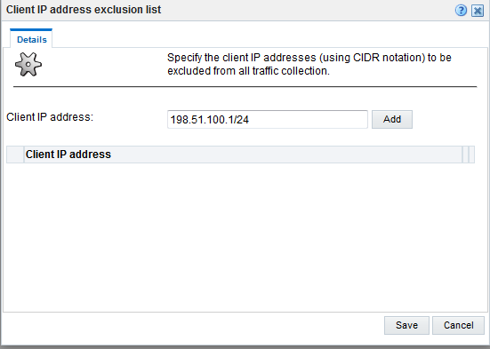
To exclude the collection of client traffic, do the following:
-
Select Configuration, then General, then Advanced settings, and then Client traffic exclusion. Click Client IP address exclusion list. The dialog shown in Figure 12-31 appears.
Figure 12-31 Client IP Address Exclusion List Dialog
Description of ''Figure 12-31 Client IP Address Exclusion List Dialog''
-
Specify the IP address of the clients whose traffic you do not want monitored. Note that this must be specified in CIDR format. For each address, click Add. When ready, click Save.
Note:
Information about the CIDR format is available at the following location:http://tools.ietf.org/html/rfc4632
-
Alternatively, you can exclude the reporting of client traffic based on the contents of the requested page's header information. Click HTTP request header exclusion list. The dialog shown in Figure 12-32 appears.
Figure 12-32 HTTP Request Header Exclusion List Dialog
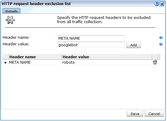
Description of ''Figure 12-32 HTTP Request Header Exclusion List Dialog''
-
Specify the header name=value pair that should be added to the list. For each pair, click Add. When ready, click Save.
12.19 Optimizing Page Download and Browser Time Reporting
The time taken for a requested page to be available to a user within their browser comprises the following components:
-
Page download time: this is the time elapsed between the first page object (normally the page request) and the last page object being delivered.
-
Page browser time: this is the time elapsed between the last page object being delivered and the page browser complete time reported by the client side instrumentation. Client side instrumentation is defined by a Browser JS Library as described in Section 7.3.1, "Defining Browser JS Library Settings".
This period can be quite considerable in the case of web pages that contain large or complex amounts of JavaScript code or if browser plugins like Flash are running. Within all major browsers, page availability is indicated by the execution of an onLoad event. This is shown in Figure 12-33.
If navigation timing is enabled, the following navigation timings are available:
-
Page Browser Interactive Time: this is the time taken before the user can click on an item on the page, that is, the page becomes interactive.
For an example of navigation timings, see Figure 4-4.
Figure 12-33 Page Download and Browser Time Reporting
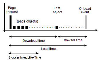
Description of ''Figure 12-33 Page Download and Browser Time Reporting''
Viewing Page Download and Browser Times
Information about page download, browser time and browser interactive time is available within the Page loading time breakdown view. An example is shown in Figure 12-34.
Figure 12-34 Page Loading Time Breakdown View
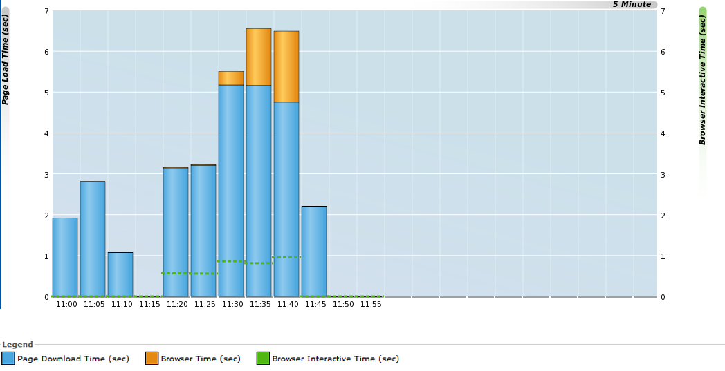
Description of ''Figure 12-34 Page Loading Time Breakdown View''
Defining an Browser JS Library is described in Section 7.3.1, "Defining Browser JS Library Settings".