HA Node Connections
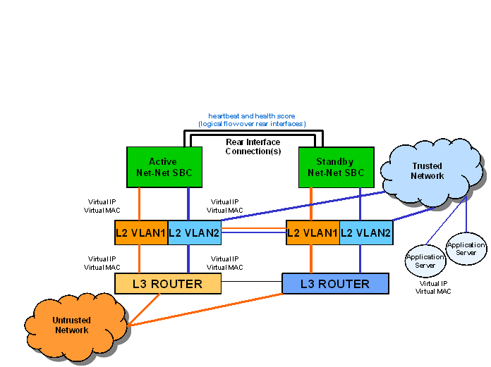
To use HA, you must establish Layer 2 and Layer 3 networks that interconnect two Oracle® Enterprise Session Border Controllers and support HA with the required physical network connections. The basic network set-up in the following diagram shows an HA node deployment where each system is connected to its own Layer 2 switch. This set-up provides a measure of added redundancy in the event that one of the switches fails.
Here, the active system is using the virtual MAC and IP addresses.

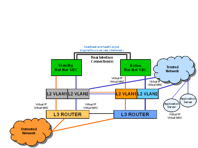
In the second diagram, the same network is shown with the HA node having experienced a switchover. The previously standby Oracle® Enterprise Session Border Controller has taken over the active role in the HA node and is using the virtual IP and MAC addresses.

Note:
Switches should never be in master-slave mode. If they are, HA will not work correctly.The following are hardware set-up and location considerations for placing an HA Node:
- You must set up each Oracle® Enterprise Session Border Controller according to the requirements and safety precautions set out in the Oracle Communications System Hardware Installation Guide.
- Each Oracle® Enterprise Session Border Controller’s media interfaces must be connected to the same switches (or other network entities), as shown in the diagram above.
- The length of the shielded crossover 10/100 category 5 Ethernet cable that connects the Oracle® Enterprise Session Border Controllers from the rear interfaces must be able to reach from the configured rear interface on one Oracle® Enterprise Session Border Controller to the configured rear interface on the other.
HA nodes use Oraclerder element redundancy protocol for its tasks. This protocol uses a connection between the rear interfaces of two Oracle® Enterprise Session Border Controllers to checkpoint the following information: health, state, media flow, signaling, and configuration.
We recommend that you use shielded category 5 (RJ45) crossover cables for all 10/100 Ethernet connections used for HA.
You can set up either single or multiple rear interface support for your HA node. For single interface support, one cable connects the two Oracle® Enterprise Session Border Controllers; for multiple interface support, two cables are used. However, the software configurations for each type of connection mode are different.
When you make these connections, do not use port 0 (wancom0) on the rear interface of the Oracle® Enterprise Session Border Controller chassis; that port should only be used for Oracle® Enterprise Session Border Controller management. Instead, use ports 1 and 2 (wancom1 and wancom2).
To cable Oracle® Enterprise Session Border Controllers using single rear interface support:


