Structured Cabling Examples
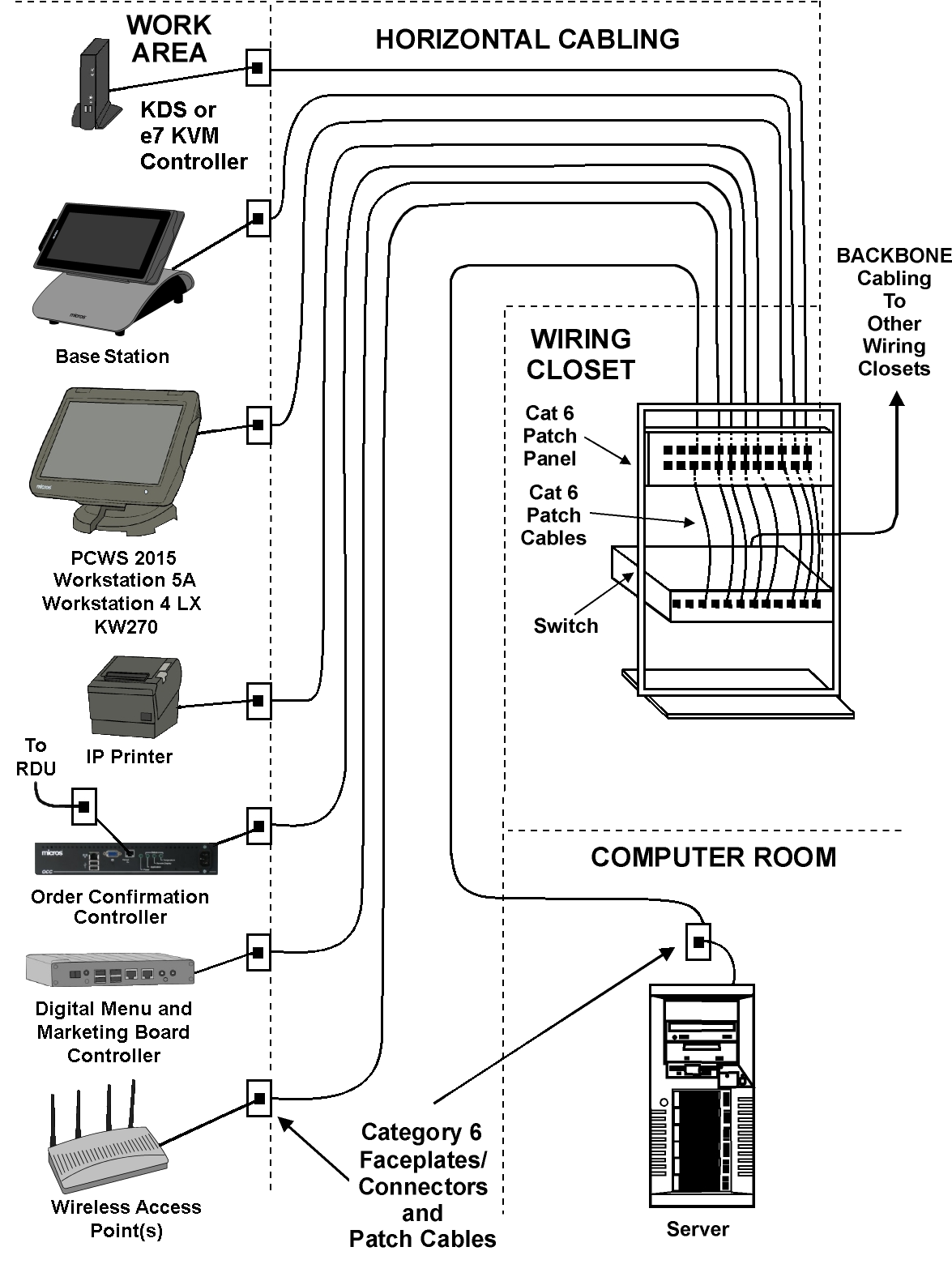
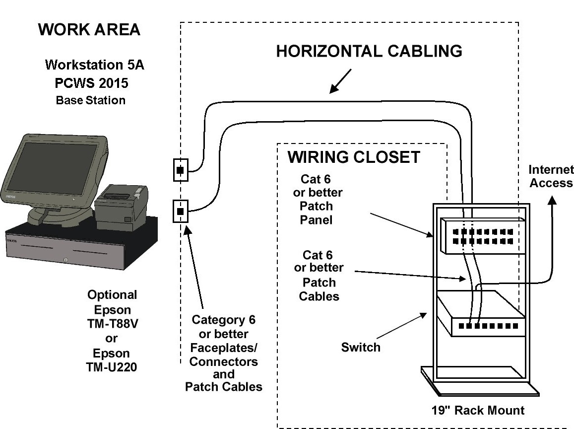
The two figures below show the MICROS workstations and peripherals integrated into a structured cabling system, including an example of a Simphony single workstation and printer installation.
-
Kitchen Display System
The KDS Controller requires a Category 6 or better faceplate and patch cable. If the 7 KVM Controller uses Ethernet, a Category 6 or better faceplate and patch cable are required. In addition to the KDS or e7 KVM, connect all LCD Monitors to dedicated, isolated ground AC outlets installed in accordance with the procedures outlined in the AC Power Requirements section.
-
Wireless Access Points
Install Wireless Access Point(s) after a site survey is performed by a qualified wireless professional.
Connect Wireless Access Point(s) to a dedicated, isolated ground AC outlet installed in accordance with the procedures outlined in the AC Power Requirements section.
-
MICROS Workstations
Each MICROS Workstation location requires a Category 6 faceplate and patch cable. Each MICROS workstation requires a dedicated, isolated ground AC outlet installed in accordance with the procedures outlined in the AC Power Requirements section.
-
IP Printers
The IP Printer is any supported Epson model equipped with Ethernet Module. Each printer requires one Ethernet channel as well as a dedicated, isolated ground AC outlet installed in accordance with the procedures outlined in the AC Power Requirements section.
-
Order Confirmation Controller
The Order Confirmation Controller requires a Category 6 faceplate and patch cable to connect to the POS application. It also requires a second Category 5e or better faceplate and patch cable as well as a Category 5e or better cable run to the Remote Display Unit housed in the pedestal.
The Installing the Order Confirmation System section provides installation instructions for the Order Confirmation System.
-
Digital Menu and Marketing Board Controller
Each Digital Menu Board Controller in a system requires a Category 6 or better Ethernet faceplate and patch cable. Each Digital Menu Board Controller(s) and each LCD monitor requires a dedicated, isolated ground AC outlet installed in accordance with the procedures outlined in theAC Power Requirements section.
-
e7 KVM Controller
If the KVM Controller Ethernet port is used, place the Category 6 or better Face Plate and Patch Cable near the unit and host workstation. The Cable Requirements section contains more information.
The KVM Controller, Monitors, and optional printer require the Preferred AC Power System detailed in the AC Power Requirements section.
-
IP Printers
The IP Printer is any supported Epson model equipped with Ethernet Module. Each printer requires one Ethernet channel as well as a dedicated, isolated ground AC outlet installed in accordance with the procedures outlined in the AC Power Requirements section.
-
Order Confirmation Controller
The Order Confirmation Controller requires a Category 6 faceplate and patch cable to connect to the POS application. It also requires a second Category 5e or better faceplate and patch cable as well as a Category 5e or better cable run to the Remote Display Unit housed in the pedestal.
The Installing the Order Confirmation System section provides installation instructions for the Order Confirmation System.
-
Digital Menu and Marketing Board Controller
Each Digital Menu Board Controller in a system requires a Category 6 or better Ethernet faceplate and patch cable. Each Digital Menu Board Controller(s) and each LCD monitor requires a dedicated, isolated ground AC outlet installed in accordance with the procedures outlined in the AC Power Requirements section.
-
e7 KVM Controller
If the KVM Controller Ethernet port is used, place the Category 6 or better Face Plate and Patch Cable near the unit and host workstation. See the Cable Requirements section for details.
The KVM Controller, Monitors, and optional printer require the Preferred AC Power System detailed in the AC Power Requirements section.
Figure 29-1 Example of MICROS Equipment in a Structured Cabling System

Figure 29-2 Example of a Single Workstation and Printer Installation for Simphony

Parent topic: Network Requirements and Planning