| Oracle® Retail Financial Integration for Oracle Retail Merchandise Operations Management and Oracle Financials Installation Guide Installation Guide Release 16.0.030 E99915-01 |
|

 Previous |
 Next |
| Oracle® Retail Financial Integration for Oracle Retail Merchandise Operations Management and Oracle Financials Installation Guide Installation Guide Release 16.0.030 E99915-01 |
|
Previous |
Next |
To enable the PeopleSoft - RFI Integration the following tasks need to be completed on PeopleSoft (PSFT) side
Integration Broker (IB) Configuration
Importing PSFT project
Security configuration
Service Configuration
Providing Web Service - GL Account Validation
Providing permission to required services
This section includes:
For more information on Installation, Please refer to PeopleTools installation guide 8.5x. Database, Web Server, PeopleTools and PIA are all installed.
Application server Domain Configuration
Application server should have been booted with Pub/Sub Servers - Yes value
|
Note: If the Application Server is not booted with this value, it needs to be restarted after changing Pub/Sub Servers parameter value to Yes. |
For more information on Application Server Domain configuration, Please refer to PeopleTools installation guide 8.5x. Section - Configuring the PeopleSoft Application Server.
To verify the Pub/Sub parameter value:
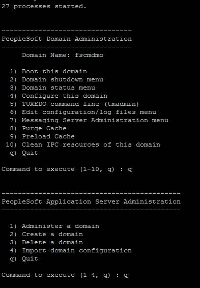
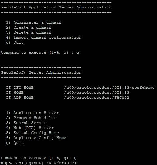
Access the PSADMIN Quick-Configure menu by launching psadmin.sh from the PS_HOME\appserv directory
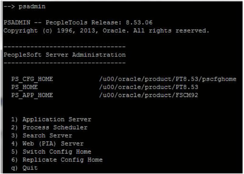
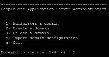
Select option 1 [Application Server]
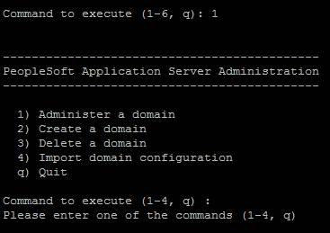
Select Option 1 [Administer a domain]
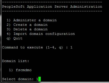
Select the domain to configure [E.g. - fscmdmo].
Select Option 4 [Configure this domain]
The system will prompt "This option will shut down the Domain. Do you want to continue? (y/n) [n] :"
Select "y" to shut down the domain
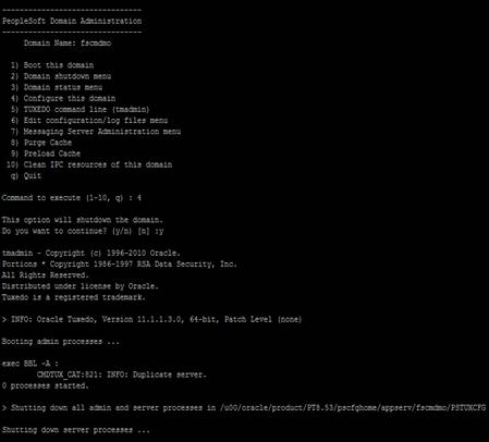
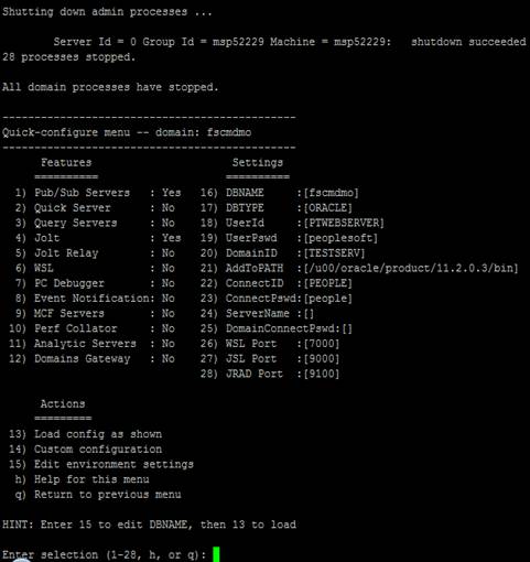
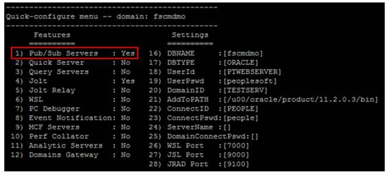
Confirm that Pub/Sub Servers parameter value is set to Yes. If not select 1 to change the value to Yes.
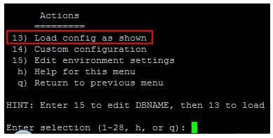
If the value is changed ,select option 13 to load the new configuration. If it is not changed, select q to return to previous menu.
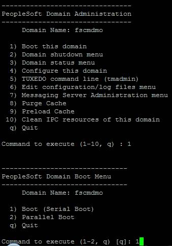
Select Option 1 to boot the domain.
System will prompt for user Options
1) Boot (Serial Boot)
2) Parallel boot
q) Quit
Select Option 1 [Serial Boot] to boot.
Exit from Configuration
Enter q to exit from Domain Administration menu
Enter q to exit from Application Server Administration menu
Enter q to exit from PeopleSoft Server Administration menu
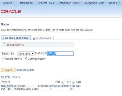
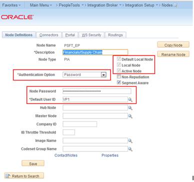
Each database involved in integration must contain a default local node definition which needs to be Active. The default authentication option to be set as required. In case of Password Node's UserId and Password values need to be configured.
Navigation: PeopleTools -> Integration Broker -> Integration Setup à Nodes
Search and Open the default node (e.g. PSFT_EP).
Make the changes and Save the page.
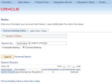
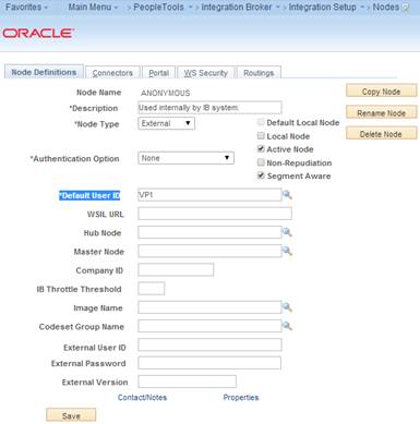
PeopleSoft uses the Anonymous node when receiving messages from third party system. The user need to verify the default user ID configured for this node is valid.
Navigation: Main Menu à PeopleTools -> Integration Broker -> Integration Setup -> Nodes
Search for ANONYMOUS node and open it.
Verify the Default User ID is valid. E.g. VP1
Prerequisites for Activating the Pub/Sub Server Domain:
To activate the pub/sub server domains, the pub/sub server option in the PSADMIN domain configuration, 1.) Pub/Sub Servers, must be set to Yes.
For more information on Application Server Domain configuration, Please refer to Enterprise 8.5x PeopleBook: Integration Broker Administration section - Activating Pub/Sub Server Domains.
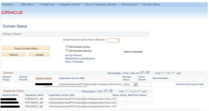
To Activate the Domain:
Navigation: PeopleTools -> Integration Broker -> Service Operation Monitor -> Administration -> Domain Status
Click Purge domain status button.
From the Domain Status drop-down list, select Active.
Click the Update button.
Click the Refresh button.
|
Note: Three dispatcher processes should appear in the Dispatcher Status grid with the status of active (ACT). On occasion it may take a few moments for the processes to start. If the processes don't immediately appear in the grid, wait a few moments and click the Refresh button again. If the three processes appear in Dispatcher Status grid, but with the status of inactive (INACT), click the Update button. |
Table 8-1 IB Configuration Activities
| Sl No | Activity | Description |
|---|---|---|
|
1 |
Set up gateway |
Define the gateway URL and load target connectors. Register nodes on the local gateway. Define integration gateway keystore values. |
|
2 |
Add target locations. |
Define the schema namespace and the service namespace. Define the target location. |
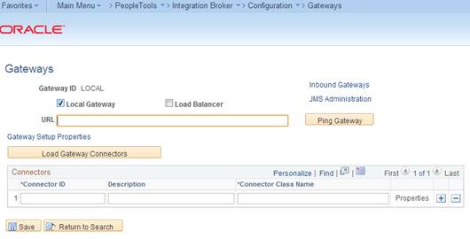
Set up the Gateway.
Define the gateway URL and load Target Connectors.
The integration gateway URL specifies the location of the PeopleSoft listening connector used to "listen" for inbound request/integrations. The target connectors handle outbound requests/integrations.
Navigation: PeopleTools -> Integration Broker -> Configuration -> Gateways.
Configure URL field value.
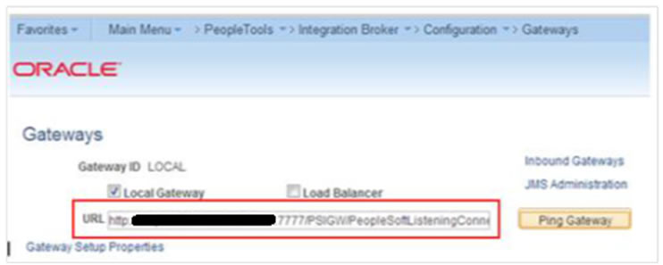
Enter the gateway URL in the following format
http://<machinename>:<port>/PSIGW/PeopleSoftListeningConnector
|
Note: The machine name is the name of the machine where PIA is installed. By default the port number is 80 for HTTP and 443 for HTTPS. If using the default port number, no need to specify it in the URL. (Ensure to have the correct port numbers specified at the time of PeopleSoft installation. |
For example:
http://peoplesofthost.example:7777/PSIGW/PeopleSoftListeningConnector
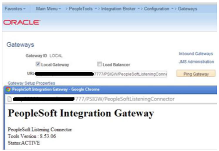
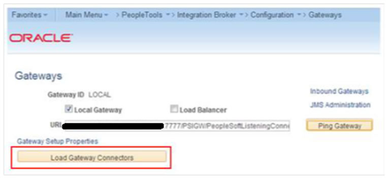
Check the Gateway Communication.
Click on "Ping Gateway" button and check the status. A successful ping means that the system can properly communicate with the gateway. If the ping is not successful, check that the correct URL is entered and that it is entered in the proper format.
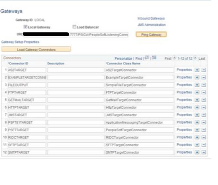
Load Gateway Connectors.
Click the Load Gateway Connectors button. A message appears that indicates the connectors were successfully loaded.
Register Nodes on the Local Gateway.
To register nodes on the local gateway:
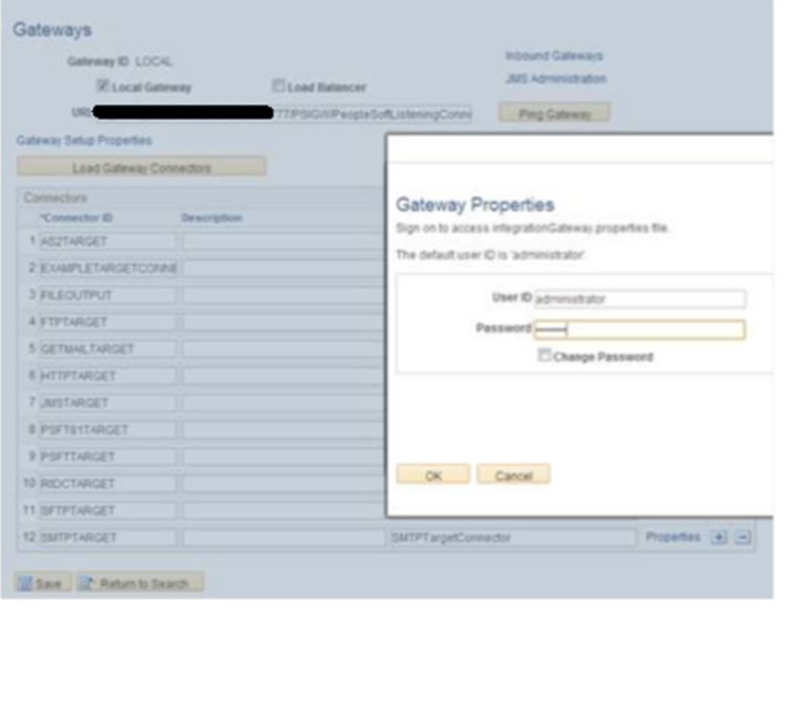
On the Gateways page, click the Gateway Setup Properties link. The Gateway Properties page appears.
Enter the user ID and password for the integration gateway. These credentials were defined when PIA was installed.
In the User ID field, enter the gateway user ID.
In the Password field, enter the gateway password.
Click the OK button.
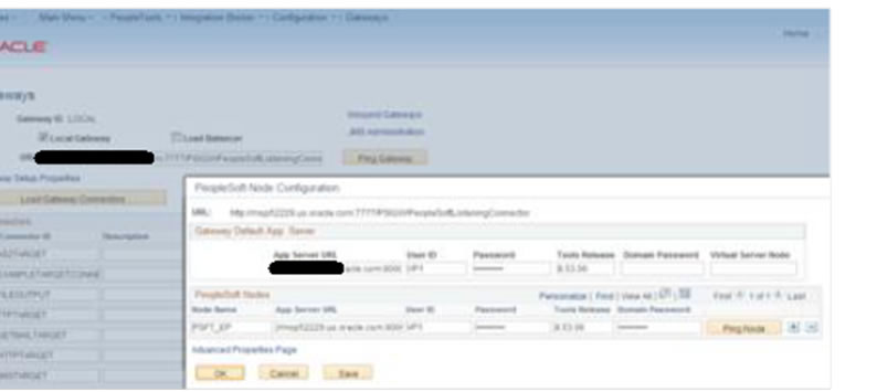
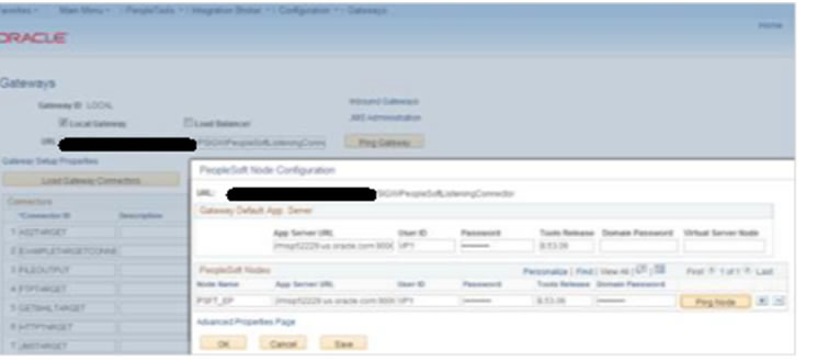
The PeopleSoft Node Configuration page appears.
In the Gateway Default App Server grid, define the following:
In the App Server URL field enter the machine name and Jolt port of the application server.
The format is //<machinename>:<port>.
For Example: //peoplesofthost.example:9000.
In the User ID field, enter the application server user ID.
In the Password field, enter the application server password.
In the Tools Release field, enter the release number of the PeopleTools version installed. For example: 8.53.06.
In the Domain Password field, enter the domain password if one was defined when the application server was configured.
In the PeopleSoft Nodes grid, define the following fields for the local default node.
|
Note: Depending on the technology you're using, you may need to define other PeopleSoft nodes in the grid. |
In the Node Name field, enter the name of the local default node.
In the App Server URL field enter the machine name and Jolt port of the application server.
The format is //<machinename>:<port>.
An example is //peoplesofthost.example:9000.
In the User ID field, enter the application server user ID.
In the Password field, enter the application server password.
In the Tools Release field, enter the release number of the PeopleTools version installed. For example, 8.53.06.
In the Domain Password field, enter the domain password if one was defined when the application server was configured.
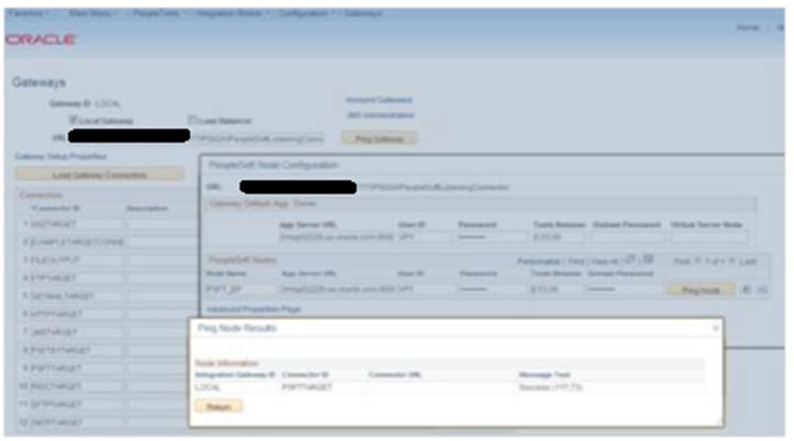
Click the Ping Node button.
A successful ping means that the integration gateway can communicate with the node. If the ping is not successful, PSAdmin needs to check the installation details regarding the gateway.
Define Integration Gateway Keystore Values
The keystore password value in the integration gateway properties file needs to be encrypted. The path to the keystore is populated during the PIA installation process, but it's good practice to confirm that the path is accurate during this task.
|
Note: Integrations will fail if you do not enter an encrypted keystore password for the secureFileKeystorePasswd property. |
For example: The following code snippet shows an example of the keystore values before they are configured:
secureFileKeystorePath= /u00/oracle/product/PT8.53/webserv/FSCMDMO/piaconfig/keystore/pskey
#secureFileKeystorePasswd=
To configure these settings confirm that the path to the keystore is correct. Next, encrypt the keystore password with the provide encryption utility, uncomment the secureKeystorePasswd property, and set the property equal to the encrypted password.
For example: The following code snippet shows an example of the keystore values after they are properly configured:
secureFileKeystorePath= secureFileKeystorePath=/u00/oracle/product/PT8.53/webserv/FSCMDMO/piaconfig/keystore/pskey
secureFileKeystorePasswd={V1.1}7m4OtVwMGDyLc1j6pZG69Q==
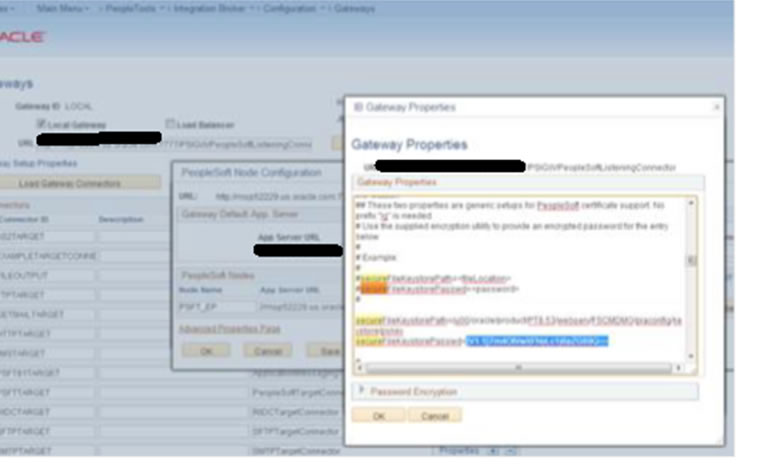
Define integration gateway keystore values.
From the PeopleSoft Node Configuration page, click the Advanced Properties Page link.
The Gateway Properties page appears.
Scroll to the ## Integration Gateway CERTIFICATE Section of the file.
Locate the secureFileKeystorePath property.
Confirm the keystore path setting:
Uncomment the secureFileKeystorePath property if it is not already uncommented.
Confirm that the path defined for the keystore path is accurate.
Enter an encrypted keystore password.
Expand the Password Encryption utility at the bottom of the page.
In the Password field, enter the keystore password.
|
Note: Password should be the domain password set at time of |
In the Confirm Password field, enter the password again.
Click the Enter button to encrypt the password.
The encrypted password appears in the Encrypted Password field.
Copy the value in the Encrypted Password field to the clipboard.
Navigate back to the secureFileKeystorePasswd property in the file.
Uncomment the property and paste the encrypted value, setting the property equal to the encrypted value.
Click the OK button
Encrypt a password using the Password Encryption Utility.
On the page where you are working, click the Password Encryption Utility arrow to display the dialog box.
In the Password field, enter a password.
In the Confirm Password field, enter the password again.
Click the Encrypt button. The encrypted password displays in the Encrypted Password field.
From the Encrypted Password field, cut the encrypted password and paste it into the appropriate location
Add the Target Location.
Define the schema namespace and the service namespace
Namespaces provide a method for qualifying element and attribute names that are used in XML documents and are identified by Uniform Resource Identifier (URI) references.
To define the schema namespace and the service namespace, use the Service Configuration page. To access the page selectPeopleTools, then selectIntegration Broker, then selectIntegration Network WorkCenter, then selectIB Configure Network and click theAdd Target Location(s) link in the left navigation pane.
PeopleTools provides the following default namespaces:
| Service Namespace | http://xmlns.oracle.com/Enterprise/Tools/services |
| Schema Namespace | http://xmlns.oracle.com/Enterprise/Tools/schemas |
You can use the default values or define different values.
To define the schema namespace and the service namespace:
Access the Integration Broker Configuration activity guide (selectPeopleTools, then selectIntegration Broker, then selectIntegration Network WorkCenter, then selectIB Configure Network).
In the left navigation pane click Add Target Location(s).
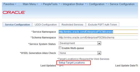
The Service Configuration page appears.
In the Service Namespace field, enter the service namespace.
In the Schema Namespace field, enter the schema namespace.
Click the Save button.
Configure Target and Secure Target Location
Target locations are URLs that PeopleSoft Integration Broker uses to build and validate XML message schemas, export WSDL documents, and as the SOAP endpoint. For REST services, target locations are URLS that PeopleSoft Integration Broker uses to export WADL documents and as the REST endpoint.
In general, the URL you specify as a target location should be an unsecured URL. If you need to enter secure target URLs, please see the product documentation for additional information before proceeding. You need to set the REST target location only if performing integrations with REST-based services.
Use the Target Locations page to define target locations. To access the page, click the Set Target Locations link on the Service Configuration page or
Navigation: PeopleTools -> Integration Broker -> Configuration -> Service Configuration
The Target Locations page provides examples of the format to enter for the target location.
The primary example shows how to enter the target location if you are using a dedicated integration gateway.
The alternate example shows the format to use if the default local node points to a different gateway where WSDL documents and XSD schemas are available. Providing an alternate example is always optional
Define target locations.
On the Service Configuration page, click the Set Target Locations link.
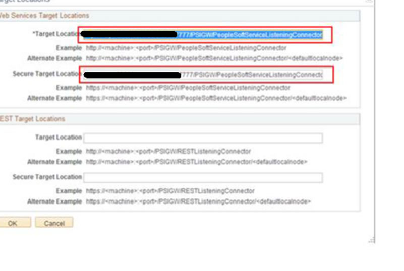
The Target Locations page appears.
In the Web Services Target Locations box, in the Target Locations field enter the target location, following the example format shown. Note that the port value you enter is the HTTP port.
|
Note: Port should be the port number referred in application URL |
If REST Services are used: In the REST Target Locations box, in the Target Locations field enter the target location of REST services, following the example format shown. Note that the port value you enter is the HTTP port.
|
Note: Port should be the port number referred in application URL |
Click the OK button.
The Service Configuration page appears.
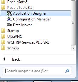
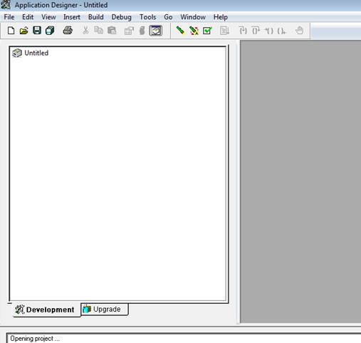
Importing the project can be done using Application Designer tool. Open the application designer from any windows work station. Refer the below screenshots.
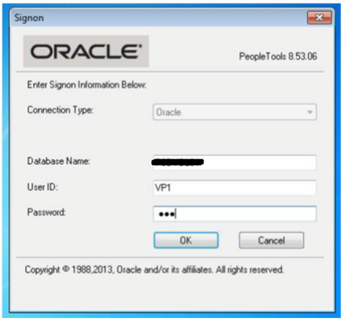
Navigation: All Programs -> PeopleTools 8.x -> Application Designer
Enter the PeopleSoft DB name (E.g. PSDVOLS1), Application User Id and Password (E.g. VP1/VP1)
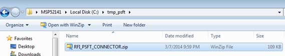
Copy the project file (zip file) in any folder in the workstation available under the <INSTALL_DIR>/psft-financial/psft-integration-broker/src/main/resources/RFI_PSFT_CONNECTOR
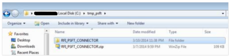
Unzip the file in any folder as required
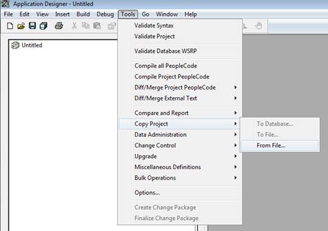
Copying Project from a File
The Copy Project From File command in the Tools menu imports PeopleTools definitions and the project definition from a file that was previously copied by using the Copy To File feature.
This section discusses how to:
– Copy a project that does not exist in the database from a file.
– Copy a project that does exist in the database from a file.
Copy a project that does not exist in the database from a file.
Select select Tools, then select Copy Project, then select From File.
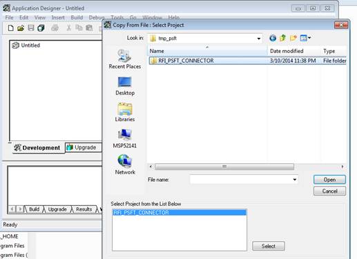
The Copy From File: Select Project dialog box appears.
Browse to locate the project file or select the file from the Projects list.
|
Note: You can use the Open button to open folders while browsing. It does not open the project file and begin the copy process.You can copy only one project from a file at a time. |
Select the Project File Folder
Select the Override Pre-Requisites check box if required.
You can select the Override Pre-Requisites check box if you want the system not to check for project prerequisites and apply the project regardless of prerequisites that have not been applied.
Click Copy.
There are two phases to the Import process: content on the XML file is written to the system cache directory (as specified in the PeopleSoft Configuration Manager) under a stage directory for the current database. Then the cache is copied to the database. When the import is complete, the cache files are deleted.
The Progress dialog box shows the progress of the Copy process as it copies each definition from the export directory into the attached database. When the Copy from File process successfully completes, the system creates a new project definition from the PeopleTools definitions in the current database. Copy process result details will be shown in Application designer local window.
If you click the Cancel button before copying the project, the project becomes invalid and the system deletes the project reference from the database.
|
Note: The below mentioned section can be skippedif previously mentioned steps are executed i.e. Copy a project that does not exist in the database from a file are executed |
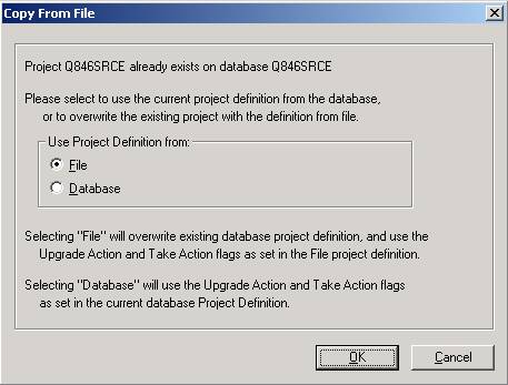
Copy a project that does exist in the database from a file.
The process for copying a project from a file when a project of the same name exists in the database is slightly different. After selecting Tools, Copy Project, From File and a project of the same name already exists in the database to which you are currently signed on, the following dialog box appears.
This prompt enables you to specify which project definition to use, the one stored in the database to which you are signed on or the one stored in the file from which you intend to copy. Keep in mind that the project definition is the metadata of the project and determines which definitions (pages, fields, records, and so on) are members of the project.
Build Project Objects.
After importing the project, all record objects [Tables and Views] need to be built from Application Designer.
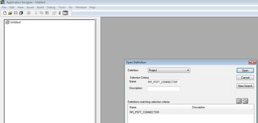
a.Open [Ctrl + O] project definition - RFI_PSFT_CONNECTOR
|
Note: If RFI_PSFT_CONNECTION project is already opened, skip this step. Same can be checked on the left side panel. |
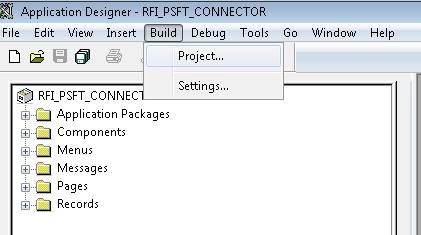
All record objects in project RFI_PSFT_CONNECTOR needs to be built. Select Build à Project menu.
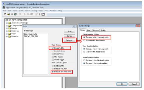
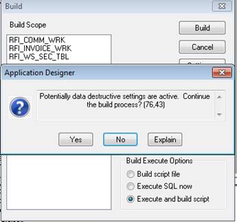
App Designer will list all the record objects to build. Select options as below.
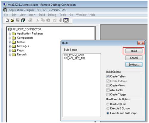
Click on Build button to build the records.
The following system message appears: "Potential data destructive settings are active. Continue the build process?"
Click yes to continue.
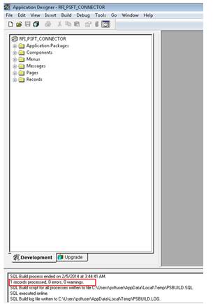
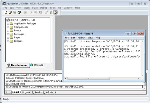
The log file should show one record processed, o errors, o warnings. If any error, click on PSBUILD.log to know more details.
If the system throws any error during Build process, refer the Error Handling / Validation section [Error When Building the Project Objects] for solution.
After checking the log details close the log file.
|
Note: Log shows only one record processed because system will build only physical records and views. For more detail refer Enterprise PeopleTools 8.4X, 8.5X PeopleBook: PeopleSoft Application Designer > Creating Record Definitions |
Note: Some configurations listed in this section might be available already after importing the project [PeopleSoft Setup Tasks - Importing PSFT project] in Target Environment. Verify the details based on the information below and do the configuration only if required.
For all Services involved in RFI Integration, the following configurations need to be completed.
Adding RFI_PL_INTEGRATION permission list to all Service Operations
Updating the Routing Parameter based on the Target system
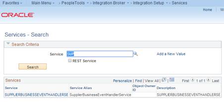
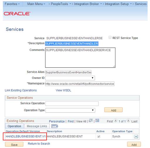
Service: SUPPLIERBUSINESSEVENTHANDLERSE
Service Operation: HANDLEBUSINESSEVENT
Navigation: Main Menu ->PeopleTools -> Integration Broker -> Integration Setup -> Services
Search for service - SUPPLIERBUSINESSEVENTHANDLERSE and click on Service Link.
From the Service Definition page, click on Service Operation link to open Service Operation.
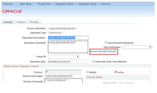
From the Service Operation Definition page, click on Service Operation Security link. This will open a popup window.
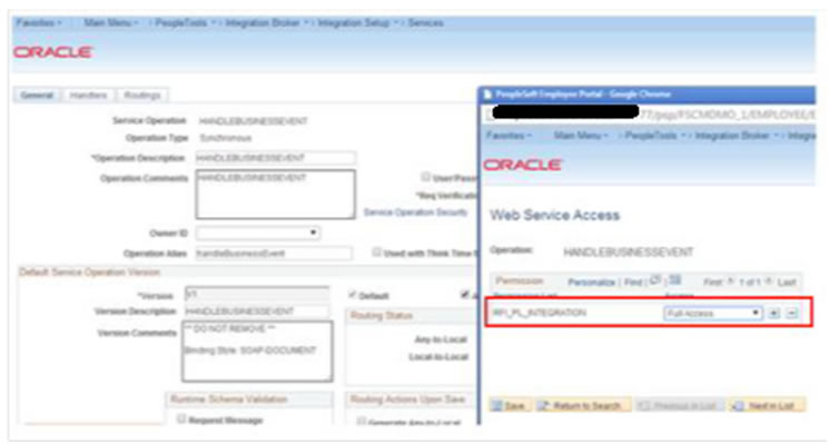
From the Service Operation Web Service Access page, add the permission list - RFI_PL_INTEGRATION (if not available already) to WebService access with full access and click Save.
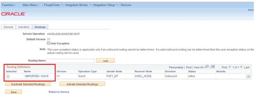
From the Routing Definition tab, go to the Routing Definition tab and click the Routing Definition Link. [Name: ~IMPORTED~10419].
From the IB Routing Definitions page, click on the Connector Properties tab and change the Primary URL value based on the Target system. The primary URL is to point to the RFI service URL that needs to be invoked from PeopleSoft. Click Save.
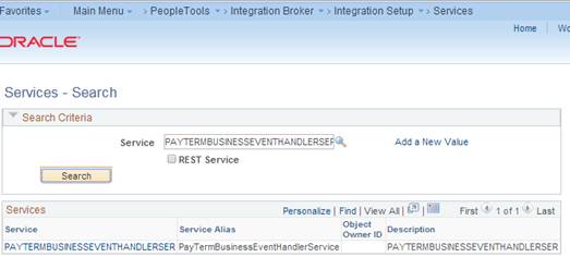
Service: PAYTERMBUSINESSEVENTHANDLERSER
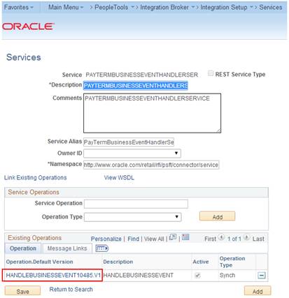
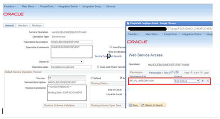
Service Operation: HANDLEBUSINESSEVENT10485
Navigation: Main Menu ->PeopleTools -> Integration Broker -> Integration Setup -> Services
From the Service Definition page, search for service - PAYTERMBUSINESSEVENTHANDLERSER and click the Service Link.
Click the Service Operation link to open the Service Operation.
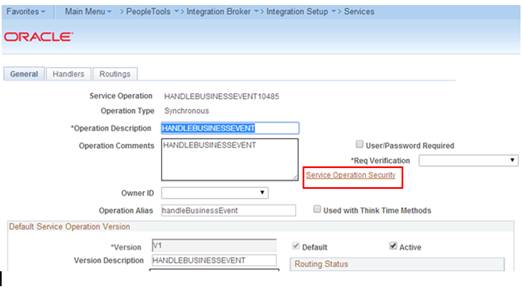
From the Service Operation Definition page, click the Service Operation Security link. This will open a popup window.
From the Service Operation Web Service Access page, add Permission list - RFI_PL_INTEGRATION (if not already available) to WebService access with full access and click on Save.
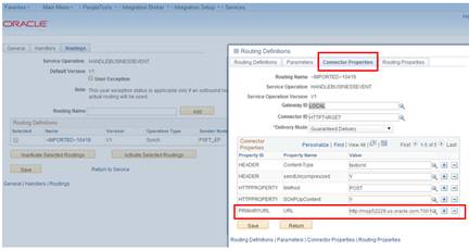
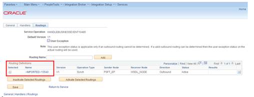
From the Routing Definition tab, go to the Routing Definition tab and click the Routing Definition Link. Routing Definition Name: ~IMPORTED~13540
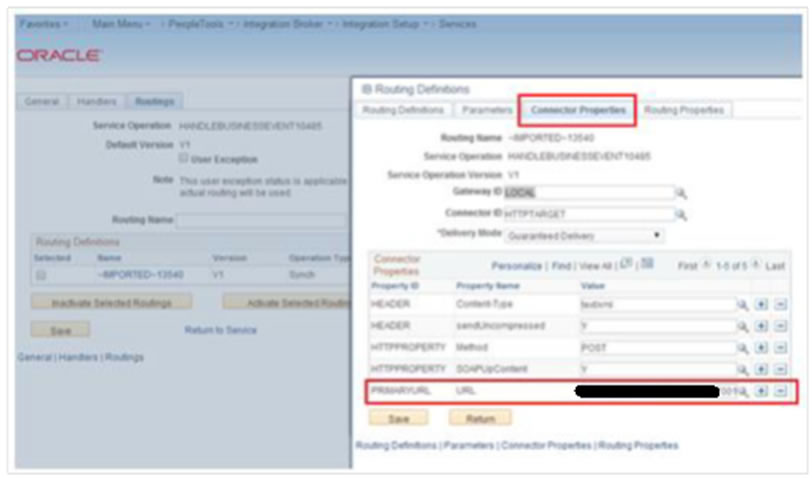
From the IB Routing Definitions page, click the Connector Properties tab and change the Primary URL value based on the Target system. Primary URL is to point to the RFI service URL that needs to be invoked from PeopleSoft. Click Save.
PeopleSoft should provide GL Account Validation WSDL to third party system to consume. It needs to be generated because the WSDL is not delivered by default.
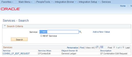
Navigation: Main Menu -> PeopleTools -> Integration Broker -> Integration Setup -> Services
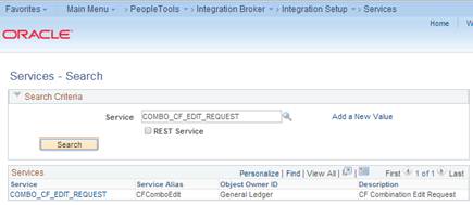
Service Name: COMBO_CF_EDIT_REQUEST
Service Operation Name: CF_EDIT_REQUEST
Verify the Request and Response messages have schemas.
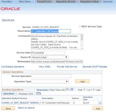
Open the service definition: COMBO_CF_EDIT_REQUEST.
Navigation: Main Menu -> PeopleTools -> Integration Broker -> Integration Setup -> Services
Click the Service - COMBO_CF_EDIT_REQUEST link.
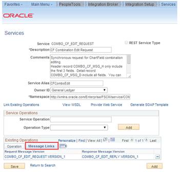
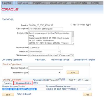
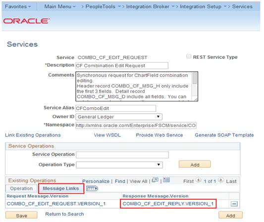
Click the Message Links tab.
Click the Request Message - COMBO_CF_EDIT_REQUEST.VERSION_1 link. It will open a popup window.
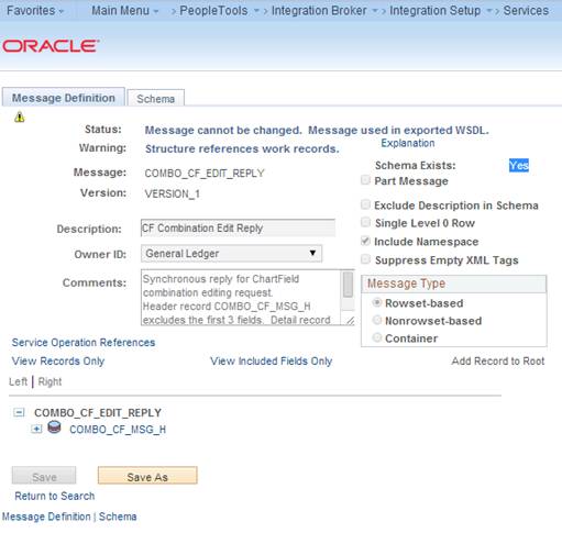
Verify the Schema Exist option is yes. If the value is No, save the message definition without any changes. It will generate the schema. A confirmation message will be displayed.
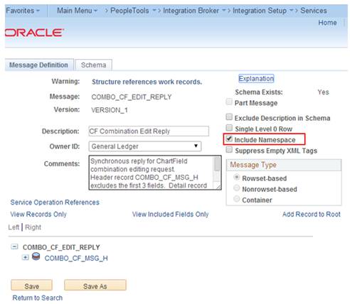
To provide the Web Service, the Include Namespace option needs to be enabled at the Service Operation level.
|
Note: For more details refer to E-IB: Service Response Message Namespace Does Not Match Description in WSDL (Doc ID 1147654.1). |
Open Service and click the Response Message link- COMBO_CF_EDIT_REPLY.VERSION_1
Click the Service link - COMBO_CF_EDIT_REQUEST.
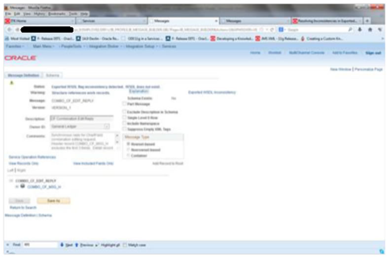
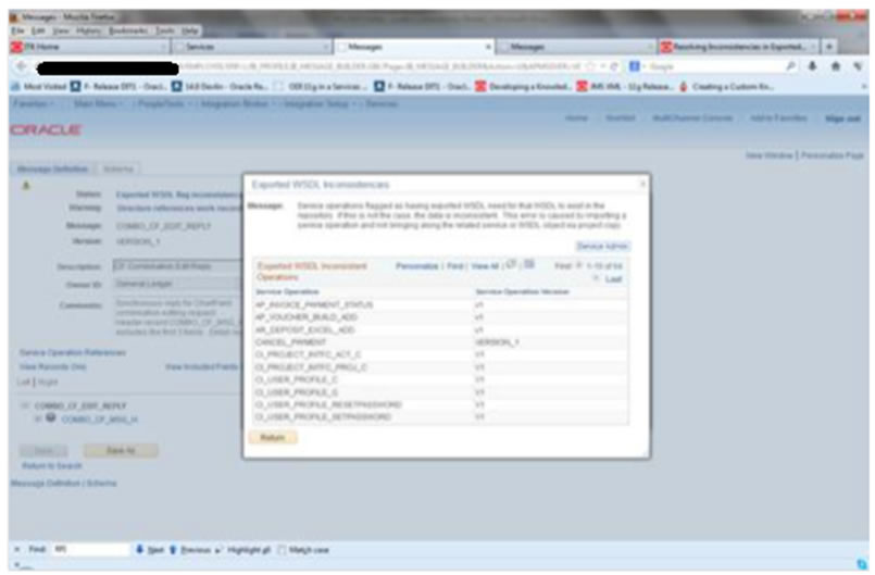
Check the Include Namespace option and click Save. If the Include Namespace option is disabled with an inconsistency, a few settings need to be completed [For more details refer http://docs.oracle.com/cd/E38689_01/pt853pbr0/eng/pt/tibr/task_ResolvingInconsistenciesinExportedWSDLandWADLDocuments-067f83.html
Click the Service Admin link on top of this window. This will open a window, which has the clear wsdl export status link. After doing this, the Include Namespace option will be enabled on the Service - Message Definition page.
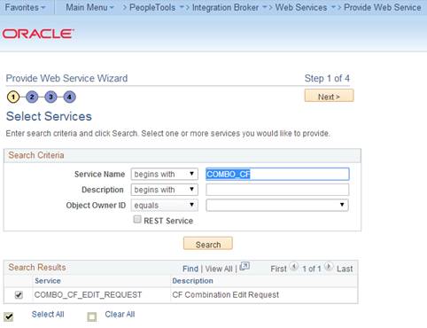
Navigation: Main Menu -> PeopleTools -> Integration Broker -> Web Service -> Provide Web Service
Open COMBO_CF_EDIT_REQUEST and click Next.
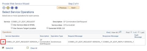
Select the Service Operation - COMBO_CF_EDIT_REQUEST.VERSION_1 and click Next.
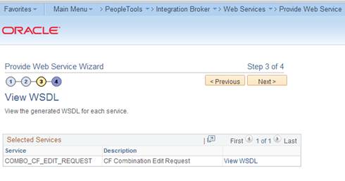
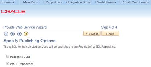
View WSDL and click Next.
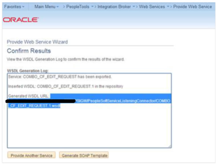
Click Finish and the WSDL will be generated.
Consume the WSDL or make the changes as required in third party system.
For example:
http://hostname:portno/PSIGW/PeopleSoftServiceListeningConnector/COMBO_CF_EDIT_REQUEST.1.wsdl
PeopleSoft should provide Drill Forward Serivice WSDL to third party system to consume. It needs to be generated because the WSDL is not delivered by default.
Validate that you are able to look up DrillForwardBackURLService is available by following the below menu navigation
Navigation: Main Menu -> PeopleTools -> Integration Broker -> Integration Setup -> Services
Lookup for "DRILLBACKFORWARDURLSERVICE". Ensure service is configured properly and "Primary URL" is pointed to correct RFI target service.
|
Note: Refer to the "PeopleSoft service is not able to deliver messages to RFI" section under Appendix - Troubleshooting PeopleSoft Services for detailed navigation. |
If above mentioned service configuration validations fails, then follow the below steps to configure the DrillBackForwardURLService in PeopleSoft else skip the below steps.
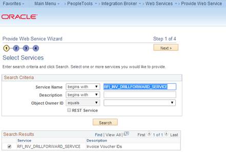
Navigation: Main Menu -> PeopleTools -> Integration Broker ->Web Service -> Provide Web Service
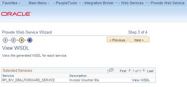
Open RFI_INV_DRILLFORWARD_SERVICE and click Next.
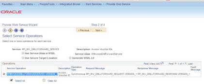
Select the Service Operation - RFIINVOICEDRILLFORWARDSERVICE.VERSION_1 and click Next.
View WSDL and click Next.
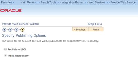
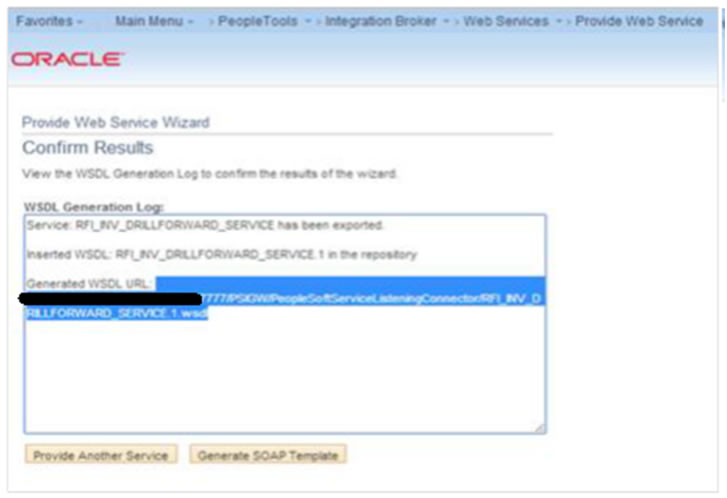
Click Finish. The WSDL is generated.
Consume the WSDL or make the changes as required in RFI.
For example:
http://hostname:portno/PSIGW/PeopleSoftServiceListeningConnector/RFI_INV_DRILLFORWARD_SERVICE.1.wsdl