| Oracle® Retail Integration Bus Hospital Administration Guide Release 16.0.21 E86947-02 |
|

 Previous |
 Next |
| Oracle® Retail Integration Bus Hospital Administration Guide Release 16.0.21 E86947-02 |
|
Previous |
Next |
The RIHA installation chapter widely focuses on ADF 12c runtime installation and deploying the tool's EAR file. For more information about domain creation and other server related information, see the WebLogic application server documents.
This section describes the installation and setup instructions including the installation prerequisite, preparing the WebLogic server, creating a WebLogic domain, verifying installation of ADF runtime libraries, extending an existing domain to add ADF run-time libraries, and deploying the EAR file. It also describes the security setup guidelines.
|
Note: The screen captures included in the following procedures are for example only. Because these procedures must be followed for each application, valid values will vary. Therefore, consider the illustrations as guides only; the values shown may not always apply. |
The RIB Hospital Administration(RIHA) requires Oracle WebLogic Server 12c (12.2.1.2.0) and built with Java 8 (JDK 1.8.0+ 64 bit or later, with the latest security updates.
|
Important: If there is an existing WebLogic 12.x.x or 10.3.xc installation on the server, you must upgrade to WebLogic 12.2.1.2.0. All middleware components associated with WebLogic server 10.3.6 should be upgraded to 12.2.1.2.0Back up the weblogic.policy file ($WLS_HOME/wlserver/server/lib) before upgrading your WebLogic server, because this file could be overwritten. Copy over the weblogic.policy backup file after the WebLogic upgrade is finished and the post patching installation steps are completed. For upgrading your WebLogic server to 12.2.1.2.0 use the appropriate Upgrade Installer. |
Take the following steps to prepare the WebLogic server:
Find fmw_12.2.1.2.0_infrastructure_Disk1_1of1.zip and download this file to your system.
Extract the contents of this zip file to your system. Use the fmw_12.2.1.2.0_infrastructure.jar file to run the installer.
Run the installer by executing the java -jar fmw_12.2.1.2.0_infrastructure.jar file. The Welcome window displays.
Click Next. The Auto Updates window displays.
Select appropriate radio button and click Next. The Installation Location window displays.
Click Browse to select the Oracle Home location where the Weblogic server is to be installed. Click Next. The Installation Type window displays.
Select Fusion Middleware Infrastructure and click Next. The installer performs the pre-requisite checks and ensures all required conditions are satisfied.
When the pre-requisite check completes successfully, click Next. The Security Updates window displays.
Prove the information and click Next. The Installation Summary window displays.
Click Install. The Installation Progress window displays.
Click Next when the installation completes. The Installation Complete window displays.
To create a schema user for the domain, take the following steps:
Run the RCU from the <MW_HOME>/oracle_common/bin folder. The Welcome window displays.
Click Next and select the Create Repository option.
Click Next. Enter the database credentials where the schema user has to be created.
Click Next. Specify the prefix to be used for the schema user creation. For example, INT. Select Metadata Services, Weblogic Services, and Oracle Platform Security Services.
Click Next. Specify the password.
Click Next. The window provides the details of tablespaces created as part of schema creation.
Click Next. The Confirmation window displays.
Click OK. The Summary window displays.
Click Create and proceed to create the schema. This could take a while to complete. The Completion Summary window displays.
To create a new WebLogic domain with JRF, take the following steps:
Run the config.sh from <ORACLE_HOME>/oracle_common/common/bin folder. The Configuration Type window displays.
Select Create a new domain, provide domain location, and click Next. The Templates window displays. By default, the Basic WebLogic Server Domain - 12.2.1.2 [wlserver] checkbox is selected. Select the Oracle JRF - 12.2.1.2 [oracle_common], Oracle Enterprise Manager [em], Oracle WSM Policy Manager - 12.2.1.2 [oracle_common], and Weblogic Advanced WebServices for JAX-WS Extension [oracle_common] check boxes.
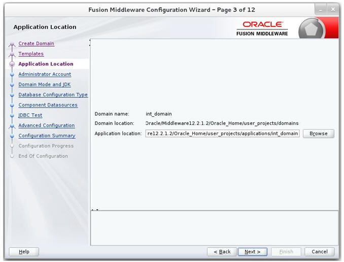
Click Next. The Application location window displays, provide the application location.
Click Next. The Administrator Account window displays. Enter the user credentials you want to use to log in to the WebLogic Administration Console.
Click Next. The Domain Mode and JDK window displays. Set the Domain Mode as Production and select the JDK version (JDK 1.8 with the latest security updates) you want to use.
Click Next. The Database Configuration Type window displays.
Select RCU Data radio button.
Select Oracle as the Vendor.
Select Oracle's Driver (Thin) for Service connections; Version 9.0.1 and later as the Driver.
Enter the Service, Host Name, Port, Schema Owner, and Schema Password for *_STB schema created using RCU.
Click Get RCU Configuration.
The Connection Result Log displays the connection status.
Click Next. The JDBC Component Schema window displays.
Click Next. The JDBC Component Schema Test window displays status on whether the JDBC tests on the schemas were successful.
Click Next. The Advanced Configuration window displays. Select all the checkboxes, except Domain Frontend Host Capture and JMS File Store options, in this window.
Click Next. The Administration Server window displays. Enter the Listen Address and the Listen Port details.
Click Next. The Node Manager window displays. Select the Node Manager Type and enter the Node Manager credentials.
Click Next. The Managed Servers window displays.
Click Add to add a managed server on which you will deploy the application.
Enter the Server Name, Listen Address, and Listen Port for the managed server.
Set the Server Groups to JRF-MAN-SVR.
Click Next. The Clusters window displays.
Click Add to add a cluster. This is an optional step in the procedure.
Click Next. The Server Templates window displays.
Click Add to add a server template. This is an optional step in the procedure.
Click Next. The Coherence Clusters window displays.
Add a coherence cluster. This is an optional step in the procedure.
Click Next. The Machines window displays.
Click Add.
Enter the Name and the Node Manager Listen Address for the managed server.
Click Next. The Assign Servers to Machines window displays. Add the Admin Server and the managed server to the computer.
Click Next. The Virtual targets window displays.
Click Add to add a Virtual target. This is an optional step in the procedure.
Click Next. The Partitions window displays.
Click Add to add a Partition. This is an optional step in the procedure.
Click Next. The Deployments Targeting window displays. Select wsm-pm from Deployments and add it to Admin Server in Targets.
Click Next. The Services Targeting window displays.
Click Next. The Configuration Summary window displays. Verify that all information described in this window is accurate.
Click Create. The Configuration Progress window displays a message when the domain is created successfully.
Click Next. The Configuration Success window displays that describes the Domain Location and Admin Server URL once the configuration is complete. 
Description of the illustration ''jrf_endofconfiggif.gif''
Click Finish to complete creating the WebLogic domain and managed servers.
This section describes the steps to verify the installation of ADF runtime libraries.
Start the Admin Server in the WebLogic domain and log on to the WebLogic Server Administration console with the admin credentials.
In the Domain Structure section, click Deployments. The deployed libraries are listed.
Click on an ADF library and go to the Targets tab. Verify that the library is targeted to both the Admin Server and the managed server. Verify these details for all the ADF libraries.
Click the Targets tab and verify that the created server is selected for that library.
This section describes the steps to extend an existing domain to add ADF runtime libraries.
Run config.sh from the Oracle_home/oracle_common/common/bin folder. The Configuration Type window displays.
Select the Upgrade an existing domain option. Click Browse and choose the location of the domain to be updated with the ADF libraries.
Click Next. The Templates window displays. Select the Oracle JRF - 12.2.1.2 [oracle_common], WebLogic Coherence Cluster Extension - 12.2.1.2 [wlserver], and Weblogic Advanced WebServices for JAX-WS Extension [oracle_common] checkboxes.
Click Next. The Application location window displays provide the application location.
Click Next. The JDBC Component Schema Test window displays which indicates the status of the schema tests.
Select the RCU Data radio button.
Select Oracle as the Vendor.
Select Oracle's Driver (Thin) for Service connections; Version 9.0.1 and later as the Driver.
Enter the Service, Host Name, Port, Schema Owner, and Schema Password for the *_STB schema created using the RCU.
Click Get RCU Configuration. The Connection Result Log displays the connection status.
Click Next. The JDBC Component Schema window displays.

Click Next. The JDBC Component Schema Test window displays which indicates the status of the schema tests.
Click Next. The Advanced Configuration window displays. Select the Managed Servers, Clusters and Coherence, and the Deployments and Services check boxes.
Click Next. The Managed Servers window displays.
Click Add to add a managed server.
Enter the Server Name, Listen Address, and the Listen Port for the managed server.
Set the Server Groups to JRF-MAN-SVR.
Click Next. The Server templates window displays. Click Add to add a server template. This is an optional step in the procedure.
Click Next. The Clusters window displays. Click Add to add a cluster. This is an optional step in the procedure.
Click Next. The Coherence Clusters window displays. Add a coherence cluster. This is an optional step in the procedure.
Click Next. The Machines window displays.
Click Add to add a computer.
Enter the Name and the Node Manager Listen Address.
Click Next. The Virtual targets window displays. Click Add to add a virtual target. This is an optional step in the procedure.
Click Next. The Partitions window displays. Click Add to add a Partition. This is an optional step in the procedure.
Click Next. The Assign Servers to Machines window displays. Add both the Admin Server and the managed server to the computer.
Click Next. The Deployments Targeting window displays.
Select wsm-pm from Deployments and add it to Admin Server in Targets.
Click Next. The Services Targeting window displays.
By default, all services are only targeted to the Admin Server.
Target all the services to the managed server.
Click Next. The Configuration Summary window displays. Verify that all information described in this window is accurate.
Click Update. The Configuration Progress window displays. The window displays a status message when the domain is updated successfully.
Click Next. The Configuration Success window displays that describes the Domain Location and Admin Server URL once the configuration is complete.
Click Finish to complete updating the existing domain with the ADF runtime.
This section describes the steps to deploy RIHA ear from rib-home. Single RIHA ear file is used for all the rib-apps and deployment is supported only from rib-home.
To deploy RIHA app from rib-home:
Download RibHospitalAdministration-Web-16.0.21 for all 16.x.xApps_eng_ga.tar and extract it to RIB_INSTALL/rib-home/tools-home.
Go to the location rib-home/tools-home/riha/conf
Edit the riha-deployment-env-info.properties with riha-admin-server-connection-url value
Ex: riha-admin-server-connection-url=t3://host:port to the location rib-home/tools-home/riha/conf
Edit target server name where RIHA app should be deployed.
Ex: riha-wls-target-name=AdminServer
This means riha app will deploys to AdminServer.
Ex: riha-wls-target-name=m1
This means riha app will deploys to Managed Server 'm1'.
Edit cluster name where RIHA app should be deployed.
If no cluster is configured then enter cluster name as ”no_cluster”
Ex:riha-wls-cluster-name=no_cluster
If any cluster is configured then enter the name of the cluster.
Ex:riha-wls-cluster-name=New_Cluster_1
Compile the riha-app. Security credentials get configured while compiling with the following command:
tools-home/riha/bin: ./riha-app-compiler.sh -setup-security-credential
Prepare Weblogic for RIHA deployment: by executing this step all the datasource required by RIHA application will be created based on the number of applications in scope of rib-deployment-info.xml and user information required for riha app to login will be created (RihaAdminGroup and user entered in riha compilation phase) tools-home/riha/bin: ./riha-app-deployer.sh -prepare-wls.
Deploy RIHA app by executing tools-home/riha/bin: ./riha-app-deployer.sh -deploy-riha-app.
Restart the WebLogic managed server.
If needed you can undeploy RIHA by executing tools-home/riha/bin: ./riha-app-deployer.sh -undeploy-riha-app.
Restrict access to the riha folder with a command like:
cd rib-home/tools-home/riha
chmod -R 700.
This section describes the steps to test the deployment.
Navigate to the post deployment screen.
Click the Control tab.
Select the application. Click Start
Click Yes.
The deployed tool is started successfully.
Click on the Testing tab and expand the deployed tool to access the URL of the tool.
