 corresponding to the Run
Pipeline that must be executed.
corresponding to the Run
Pipeline that must be executed.Process Modeling Framework (PMF) is a design and execution framework that enables the Process Pipeline developers to implement various Pipelines modeled by the Business Analysts. The Process Pipeline developers use the framework to orchestrate the Business Pipelines and the Run Pipelines within OFSAA and to design the artifacts that participate in the Pipelines to complete their implementation.
This chapter provides information about the usage of the Process Modeling Framework (PMF) feature in the Oracle Financial Services Regulatory Reporting for Us Federal Reserve (OFS REG REP US FED) application.
NOTE:
For more information about the Process Modeling Framework (PMF) feature in OFSAA, see the Process Modelling Framework Orchestration Guide.
This chapter includes the following topics:
· Overview
· Designing a Pipeline in OFS REG REP US FED
· Verifying the Execution Logs
In OFS REG REP US FED, Process Modelling Framework (PMF) is used to create a Run definition in a Run process. The visual representation of the Run is enabled through PMF by the construction of a Run Pipeline. PMF is a feature in parallel to the Run Management feature. Through the PMF, you can execute the following two Ready-to-use Runs for data loading:
· Financial
Services Regulatory Reporting for US Federal Reserve -Lombard Risk
Integration Pack (OFS REG
REP US FED) Sourced Run
· Financial
Services Regulatory Reporting for US Federal Reserve -Lombard Risk
Integration Pack (OFS REG
REP US FED) Execution Run
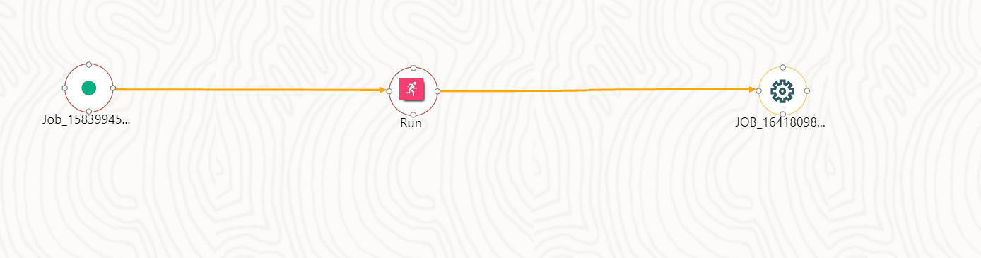
You can design the process flow diagrams for both the processes (Business Process Pipeline and Run Pipeline). This is an example of a process flow diagram for a Run Pipeline (for OFS REG REP US FED Sourced Run).
After you create, design, and define the process in the process flow diagram, you must assign values to the Run parameters, and execute the Run. You can execute a Run Pipeline from the UI or using a command-line utility called wfExecExternal.sh.
This section includes the following topics that describe the Run Pipeline execution from the UI:
· Selecting the Run Parameters and Executing the Run
· Verifying the Execution Logs
NOTE:
For more information about executing the Run Pipeline using a command-line utility, see the section Using Command Line Utility in the Process Modelling Framework Orchestration Guide.
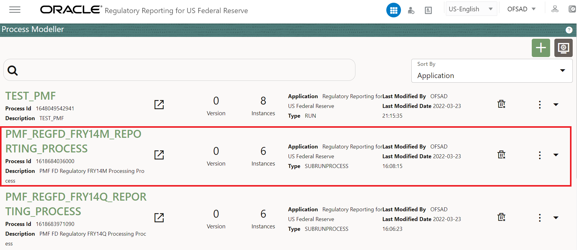
After designing and saving the process flow diagram, the Process is listed on the Process Modeler page.
To select the Run parameters and execute the Run, follow this procedure:
1. On the Process Modeler page, click the More icon corresponding to the Run
Pipeline that must be executed.
Figure 89: Process Modeler Screen

2. When you click Execute Run, the Select Run Params Window is displayed.
Figure 90: Select Run Parameter Screen

3. Select the Execution Type as With Parameters from the drop-down list.
4. Select or enter the required values for each field as follows.
Table 29: Run Parameter Fields and Descriptions
Field Name |
Description or Instruction |
Reporting Currency |
Enter the Reporting Currency Code used to calculate the amount during the data population in the target table. |
Legal Entity |
Select the Legal Entity Code to identify the legal entity used for the Run. |
Consolidation Type |
Select the Consolidation Type of legal entities on a solo or consolidation basis. In a Solo Run, only the selected legal entity is used. In a Consolidated Run, along with the selected legal entity, all its child legal entities are also used. |
Intra Company Elimination |
Select the Intra Company Elimination type to eliminate (YES) or skip the elimination (NO) of Intra Company Accounts during a Consolidated Run. |
Consolidation Hierarchy |
Enter the Legal Entity Hierarchy used for the consolidated run. This parameter is not required for the Solo Run. |
GAAP Code |
Enter the required accounting standard. |
FIC MIS Date |
Select the extraction date. |
Run Execution Description |
Enter a longer description of the Run. |
5. When you click OK, the Run execution begins. The Select Run Params Window closes.
NOTE:
The execution of the Run Pipeline is triggered using the selected FIC MIS DATE. The Run SKey is generated and inserted into the DIM_RUN table. For the Run SKey generated, the corresponding user-selected Run parameters are inserted into the RUN_EXE_PARAMETERS table.
After selecting the Run Parameters and beginning the Run execution, verify the progress of the Run.
To verify the Run Execution Progress, follow this procedure:
1. On the Process
Modeler Page, click the More
icon corresponding
to the Run Pipeline that must be verified. Click Process
Flow Monitor.
Figure 91: Process Modeler Run Execution Screen
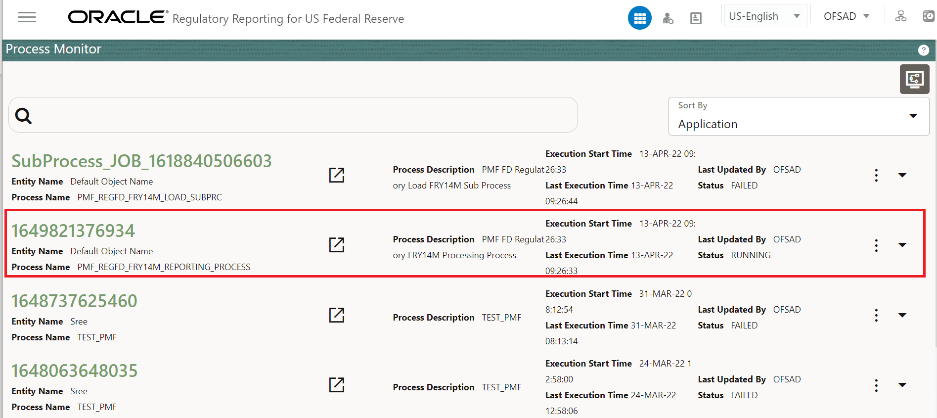
2. The Process Monitor Window is displayed. You can see the generated Process Flow ID, the Run Execution timestamp, and the status of the Run Execution. To verify the Run Execution Status at the Pipeline level, click the corresponding Process Flow ID.
Figure 92: Process Monitor Screen
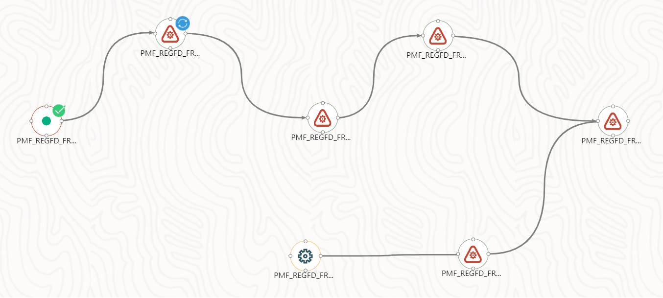
3. The Process
Flow Diagram Window is displayed. The 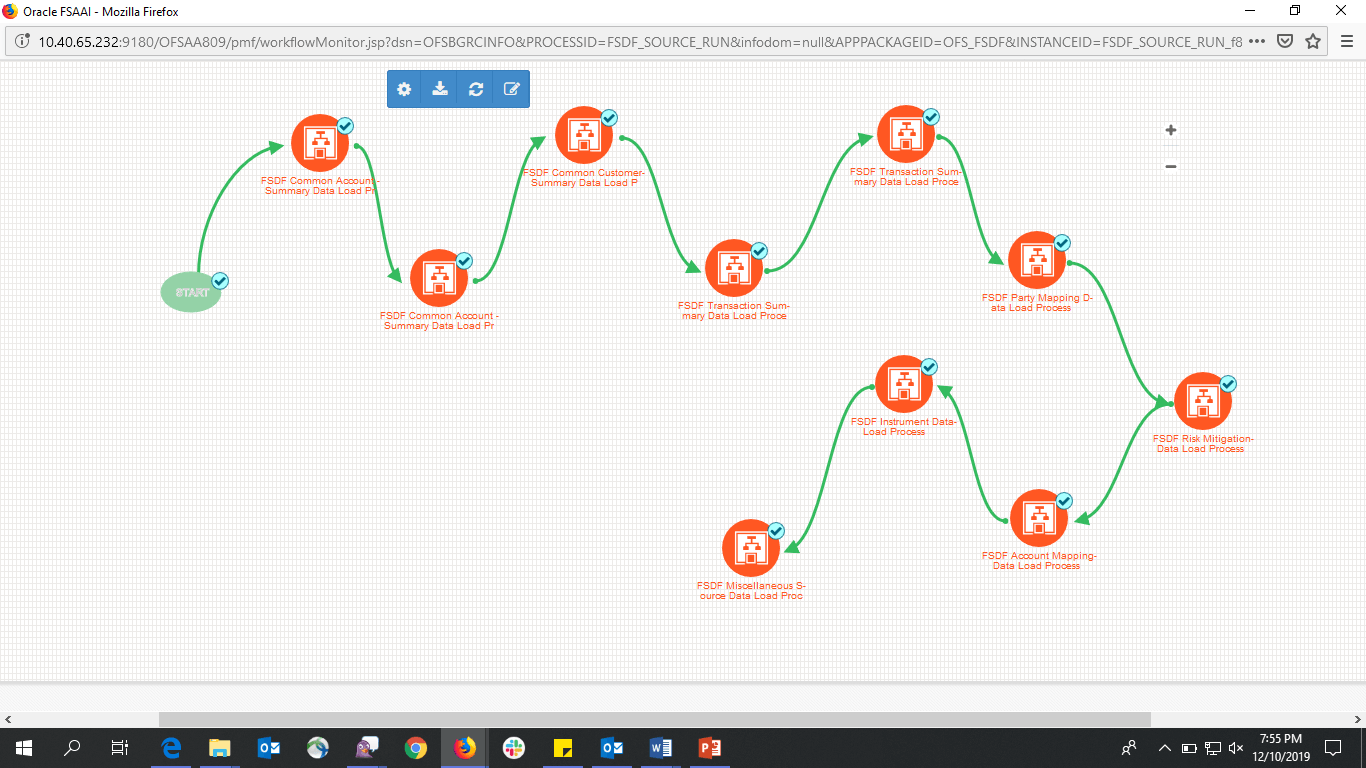 icon
at each Sub Pipeline indicates that the Run execution is successful.
icon
at each Sub Pipeline indicates that the Run execution is successful.
NOTE:
The  icon
at each Sub Pipeline indicates that the Run execution is unsuccessful.
icon
at each Sub Pipeline indicates that the Run execution is unsuccessful.
Figure 93: Run Pipeline Process Flow Diagram
You can access the execution logs to verify the details of the Run.
To verify the execution log, follow these steps:
1. In the Process
Monitor Window, click the required Process Flow ID. The Process
Flow Diagram is displayed in a new window. Hover on the required Sub Pipeline.
Four icons appear. Click the log  Icon.
Icon.
Figure 94: Sub Pipeline
2. The Execution Logs window is displayed. Click the required metadata to verify the execution log.
Figure 95: Execution Logs

3. The Activity window is displayed. Click Execution Log.
Figure 96: Activity Logs

4. Click Execution Logs. The Log File details page is displayed.
Figure 97: Log File
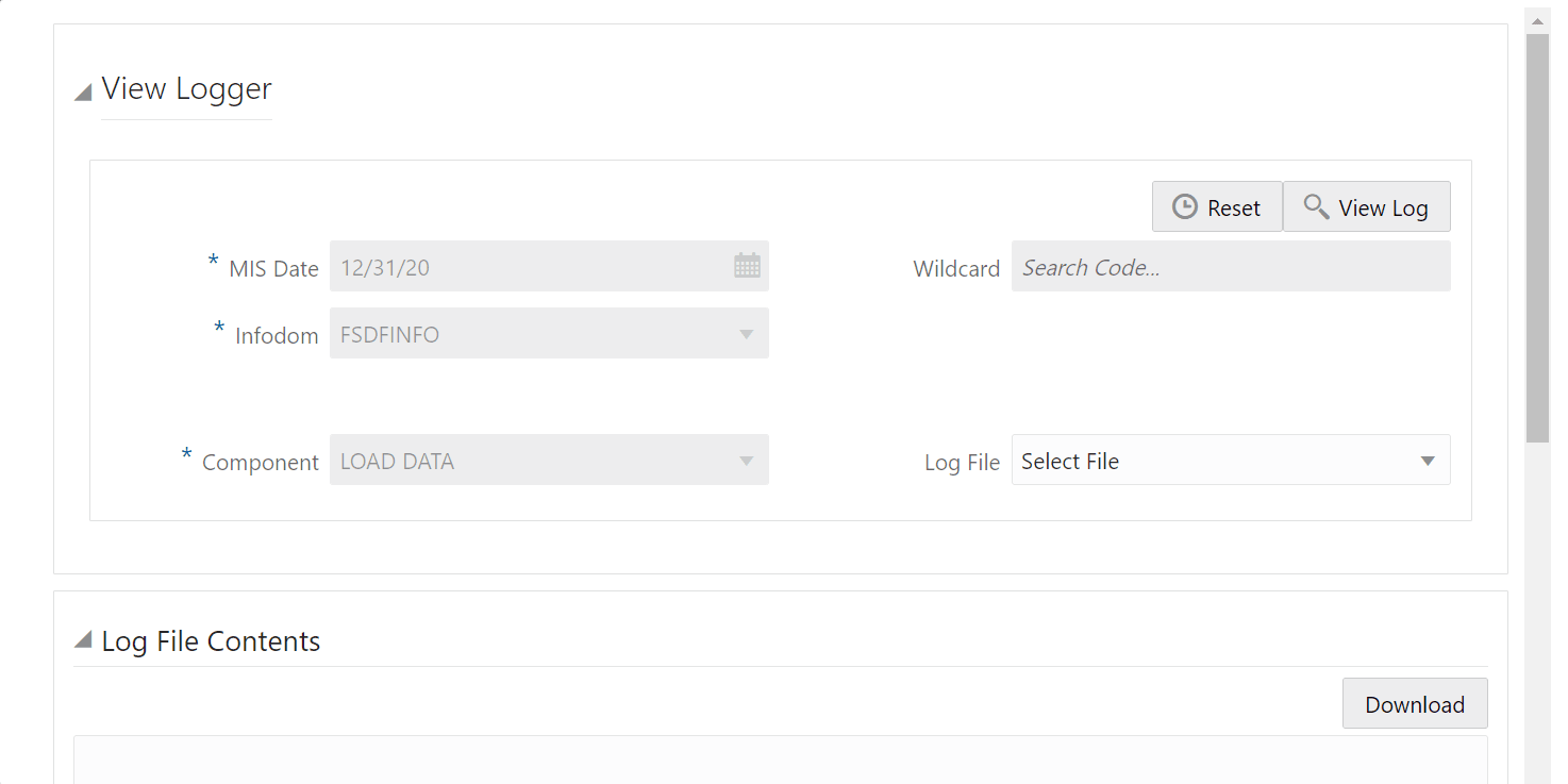
5. Select the Log File that you wish to view from the drop-down list and click View Log. The Run execution log details are displayed.
Figure 98: View Run Execution Log window
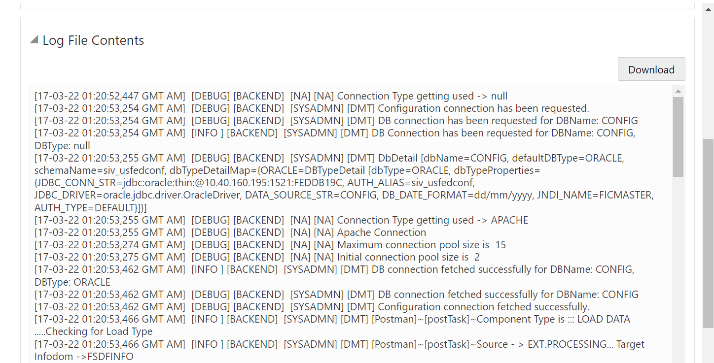
6. The Run execution log details are listed in a separate window.
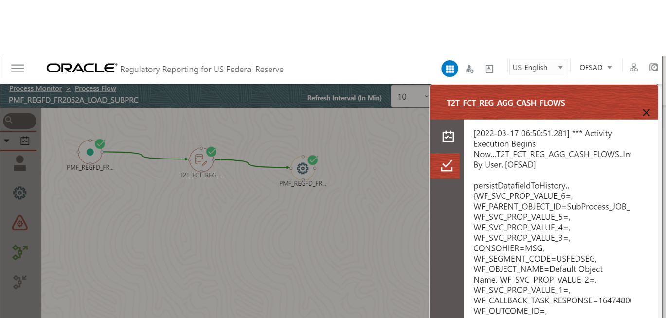
Alternatively, to verify the execution logs, click the
 icon in the Process
flow diagram window. The log details of the Run execution are displayed
in a new window.
icon in the Process
flow diagram window. The log details of the Run execution are displayed
in a new window.
Figure 99: Run Execution Logs
For detailed information about the complete functioning of the PMF, see the Process Modelling Framework Orchestration Guide.
The Run Management functionality is no longer available from 8.1.0.0.0 releases of all OFSAA applications since the ready-to-use Reporting Run is now using Run Pipeline in the Process Modelling Framework. If you still wish to use the Rule Run Framework (RRF), you can consider the following additional configuration steps to achieve the Run Management features.
NOTE:
The product direction is to start using the Process Modelling Framework Run pipelines for Regulatory Reporting Run executions instead of obsolete Reporting Run (RRF). The ready-to-use version of the Reporting Run (RRF) will no longer be updated in the Regulatory Reporting Installer. All the new tasks added for the reporting will only be a part of the PMF Run Pipeline.
The Run Management User Interface was used to capture and store the run parameters for downstream usage.
To execute the RRF Run with the parameter support, follow this procedure:
1. After logging into the OFSAAI applications page, navigate to Regulatory Reporting for US Federal Reserve, select Process Modelling Framework and then select Process Modeller.
Figure 100: Process Modeller Page

2. On the Process
Modeller page, click the Add  icon to create a new Run Pipeline
The Process
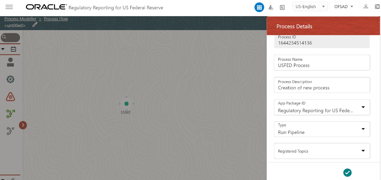
Details page is
displayed.
icon to create a new Run Pipeline
The Process
Details page is
displayed.
Figure 101: Process Details page

3. Select or
enter the required values in the following mandatory fields.
Other fields in the Updated Process Details page can be ignored.
Table 30: Process Details Fields and Descriptions
Field Name |
Description or Instruction |
Process Name |
Enter the process name. |
Process Description |
Enter the process description. |
App Package ID |
Select the Application Package ID as Regulatory Reporting for US Federal Reserve from the dropdown list. |
Type |
Select the process type as Run Pipeline. |
Infodom |
Select the infodom from the dropdown list. |
Segment |
Select the USFED segment from the dropdown list. |
Figure 102: Updated Process Details page
4. Click OK
 icon
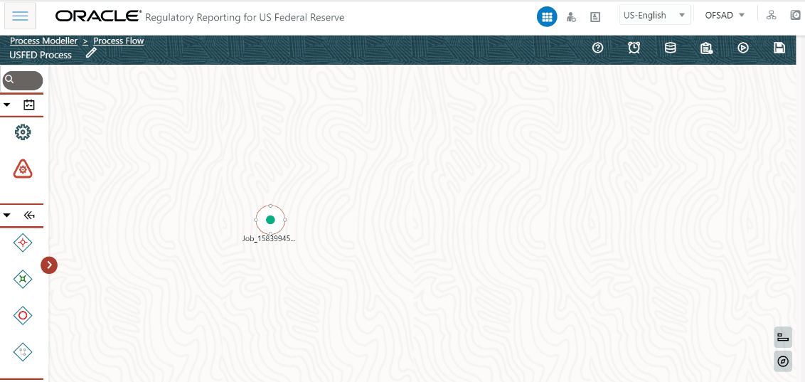
to save the created process. The Process Saved page is displayed.
icon
to save the created process. The Process Saved page is displayed.
Figure 103: Process Saved Page
5. Add the Run Type Node
 icon
by dragging and dropping onto the canvas. The USFED Run Details page is
displayed.
icon
by dragging and dropping onto the canvas. The USFED Run Details page is
displayed.
Figure 104: USFED Run Details page
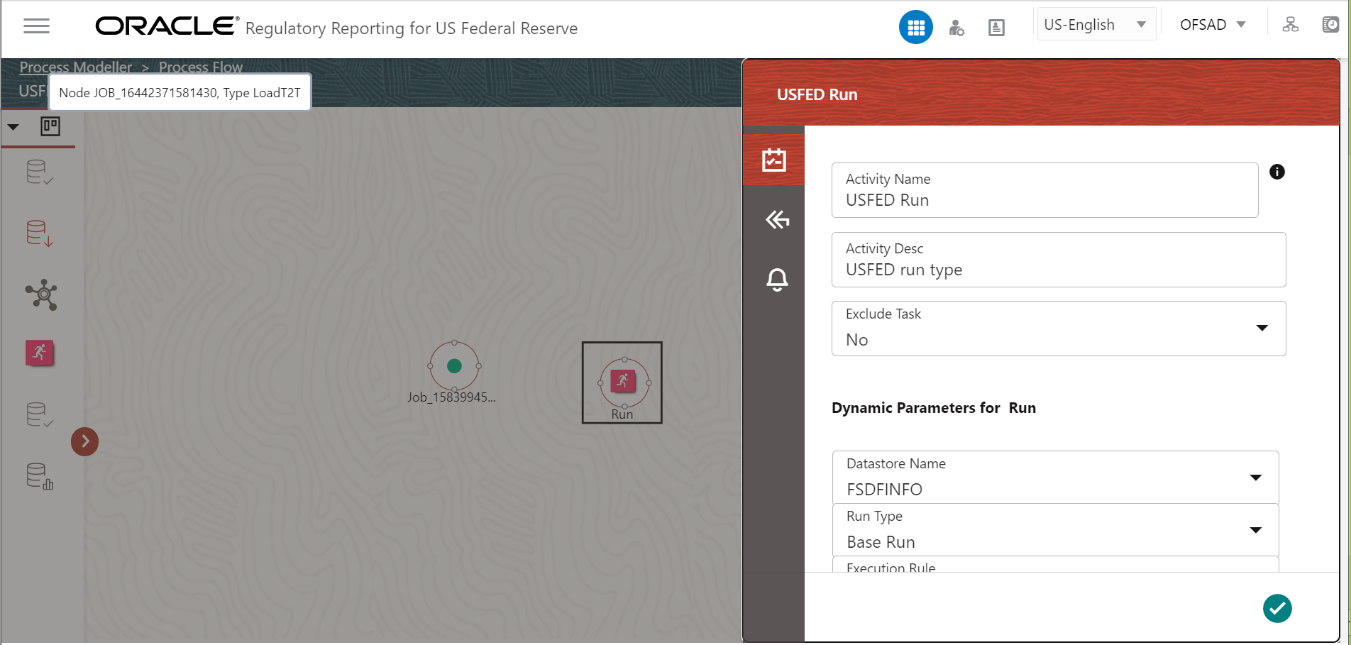
6. Select or enter the required values for each field as follows.
Table 31: USFED Run Details Fields and Descriptions
Field Name |
Description or Instruction |
Activity Name |
Enter the activity name. |
Activity Description |
Enter the activity description. |
Exclude Task |
Select No from the dropdown list. |
Dynamic Parameters for Run |
|
Datastore Name |
Select the infodom from the dropdown list. |
Run Type |
Select the run type as Base Run from the dropdown list. |
Execution Rule |
Select the execution rule as USFED Execution Run from the dropdown list. |
Run Parameters |
Enter the runtime parameter as WF_RUNSK. |
7. Click OK
icon
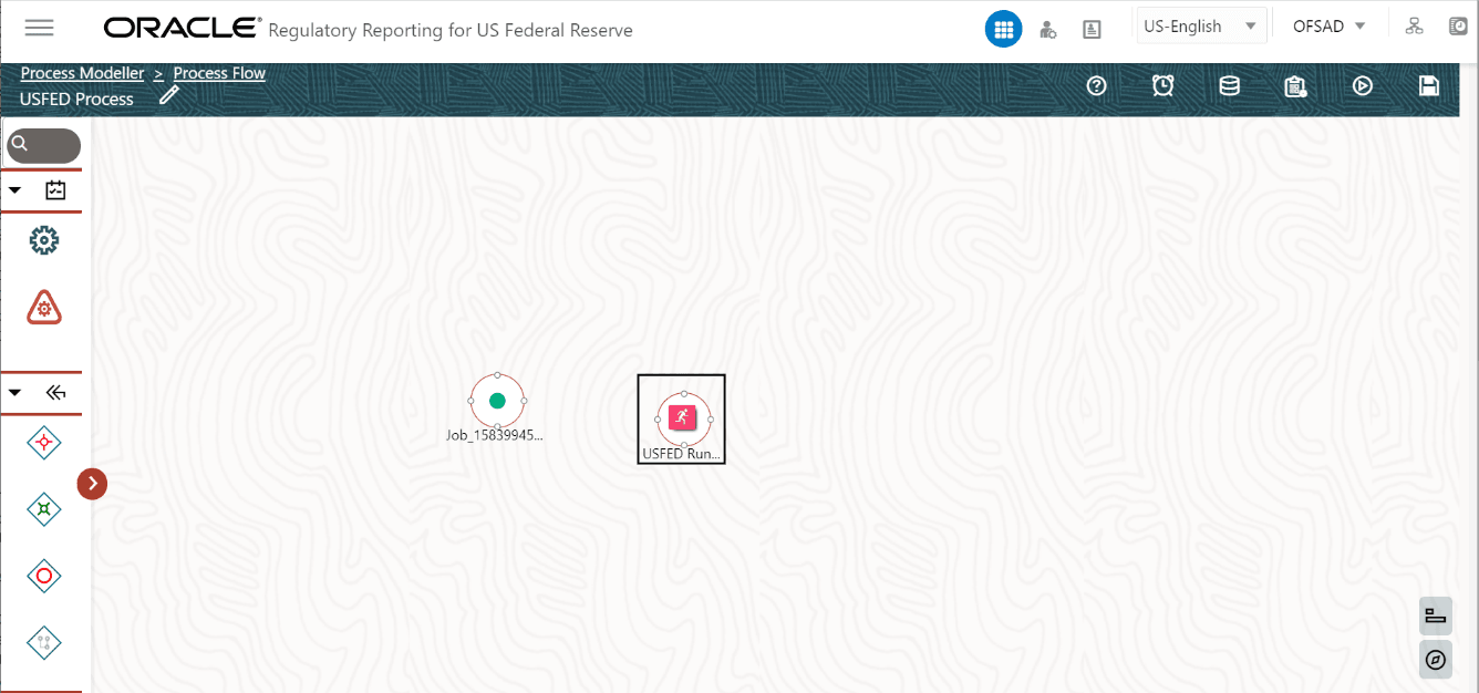
to save the entered run type node details.
Figure 105: USFED Run Type Saved Page
8. Add the Service
Task icon to end the Run Pipeline and connect the
Nodes using the Connectors in the USFED Process Canvas page.
icon to end the Run Pipeline and connect the
Nodes using the Connectors in the USFED Process Canvas page.
Figure 106: USFED Process Canvas page
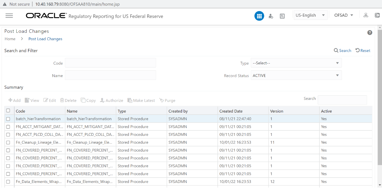
9. These steps will enable RRF run execution through the PMF along with the parameters’ support. There is an additional step required since the PMF run pipeline will be generating the Run Surrogate Key (Run Skey) and store the parameters against this Run Skey. But, when RRF run gets invoked, there will be a new Run Skey that will be generated for RRF. Since we need parameters for RRF run, it is expected to copy the run parameters from the PMF run to RRF run. The same can be achieved using the Post Load Changes (PLC).
10. Create a Data
Transform (DT) for the Run with the Run Parameters under PLC with the
Standard Run Parameters and an additional Parameter as WF_RUNSK
to copy the data of RUN_EXE_PARAMETERS of WF_RUNSK to load into the RUN_EXE_PARAMETERS
for $RUNSK.
Figure 107: Post Load Changes Page
11. For example : DT can contain an Insert command as follows.
INSERT INTO RUN_EXE_PARAMETERS
(V_PARAM_ID,
V_SEGMENT_CODE,
N_RUN_SKEY,
V_PARAM_VALUE_CODE,
V_HIER_NODE_CODE,
V_LEAF_CONDITION,
V_HIER_NODE_DESC)
SELECT V_PARAM_ID,
V_SEGMENT_CODE,
I_RUN_SKEY AS N_RUN_SKEY,
-- The $RUNSK for Reporting Run
V_PARAM_VALUE_CODE,
V_HIER_NODE_CODE,
V_LEAF_CONDITION,
V_HIER_NODE_DESC
FROM RUN_EXE_PARAMETERS
WHERE N_RUN_SKEY = I_WF_RUN_SKEY -- The WF_RUNSSK from
PMF
12. In the Financial Services Data Foundation application, select Rule Run Framework, and then select Process.
Figure 108: Process Creation page

13. Click New
 to create a
process in the Regulatory Rules Framework to add the newly created DT
with an optional parameter as WF_RUNSK. Select
the Folder as USFEDSEG and click
OK.
to create a
process in the Regulatory Rules Framework to add the newly created DT
with an optional parameter as WF_RUNSK. Select
the Folder as USFEDSEG and click
OK.
Figure 109: Process Segment Selection Page

14. Select or enter the required values for each field as follows.
Table 32: USFED Run Details Fields and Descriptions
Field Name |
Description or Instruction |
Code |
Enter the process code. |
Name |
Enter the process name. |
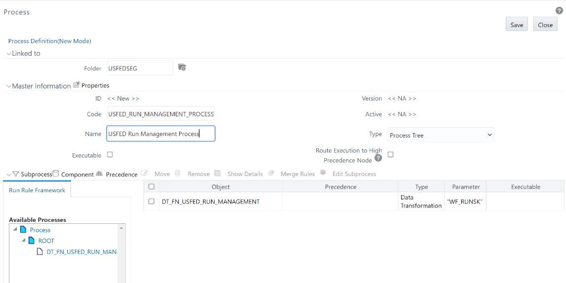
Figure 110: Process Definition Page

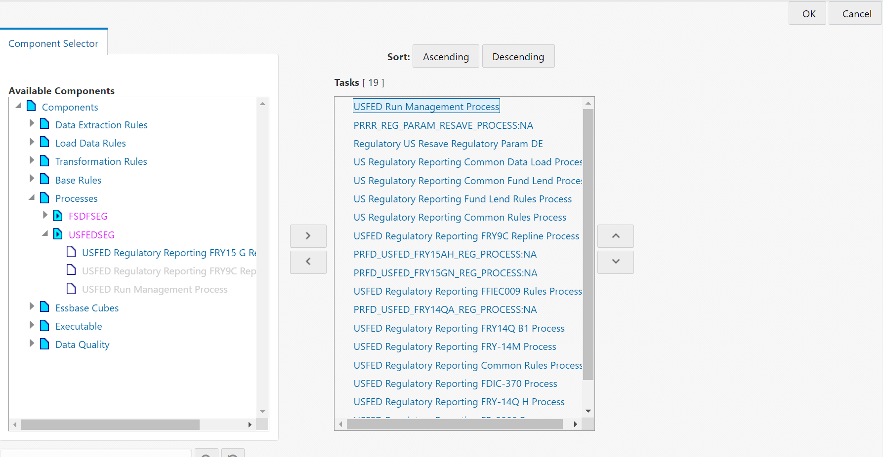
15. Select the Component option and the Component Selector window is displayed.
Figure 111: Component Selector Window

16. From the Available
Components column, select Transformation Rules, then select Database Functions
Transformations and then select the corresponding DT, click Move
 icon to add the DT to the Tasks
In Root column.
icon to add the DT to the Tasks
In Root column.
17. In
the Tasks In Root column, select the Process and right click on
the Setting  icon to add the parameters. The
Add Parameters Window is displayed.
icon to add the parameters. The
Add Parameters Window is displayed.
Figure 112: Add Parameter Window

18. Click OK to add the parameter details to the Data Transformation.
19. Click OK in the Component
Selector window to save the Data Transformation.
The Process Definition Save page is displayed
Figure 113: Process Definition Save page
20. Click Save button to save the process details.
21. In the Financial Services Data Foundation application, select Rule Run Framework, and then select Run.
Figure 114: Run Summary Page

22. Select the USFED Reporting Run from the Run Summary page.
Figure 115: Run Summary Page

23. Click Edit icon to edit the run details The Edit Run Details page is displayed.
Figure 116: Edit Run Details page
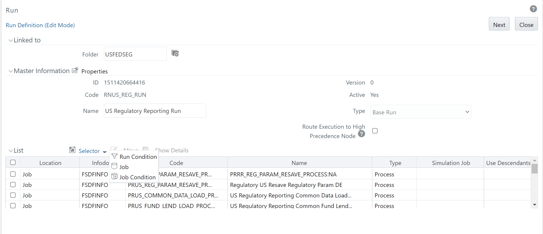
24. Click the
Selector dropdown list and select the Job option. The Component
Selector window is displayed.
From the Available Components
column, select Processes, then select USFEDSEG
and then select the corresponding process, click Move
 icon
to add the newly created
process to the USFED reporting run as the first task.
icon
to add the newly created
process to the USFED reporting run as the first task.
NOTE:
The selected component must always be on top of the
Tasks table. You can use the Move Up  icon
to do the same.
icon
to do the same.
Figure 117: Component Selector Run Window
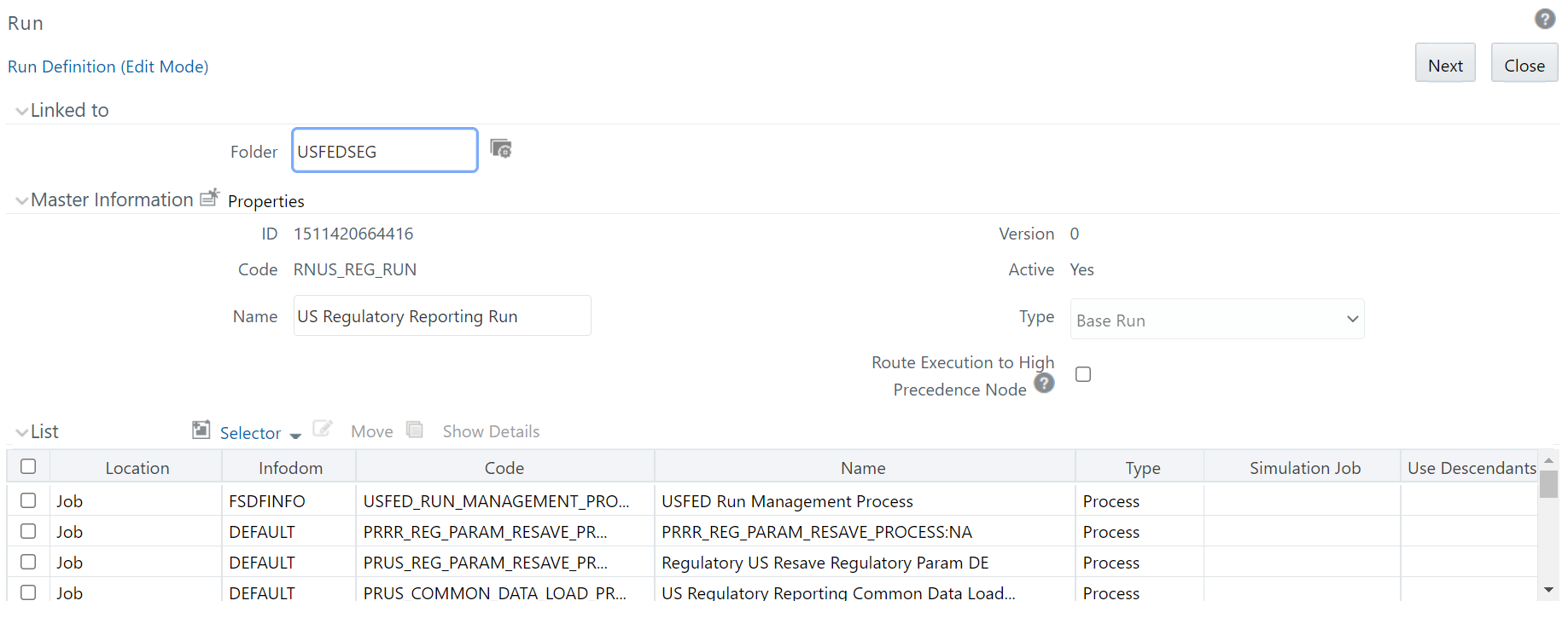
25. Click Ok button to save the run details. The updated Run Definition page is displayed.
Figure 118: Updated Run Definition Page
26. Click Next button to view the added process to the run. The Process Added to Run page is displayed.
Figure 119: Process Added to Run page

27. Click Save button and a confirmation window is displayed.
Figure 120: Confirmation Window

28. Click No to add the process to the existing USFED Regulatory Run.
29. Execute the initially created run from the Process Modeler screen with the run parameters (similar to Run Management). The PMF generates a Run Skey that will be provided as inputs to the RUN_EXE_PARAMETERS.
30. Execute the USFED Regulatory Reporting Run that creates another Run Skey and the DT retrieves the parameters.