 corresponding
to the Run Pipeline that must be executed.
corresponding
to the Run Pipeline that must be executed.Process Modeling Framework (PMF) is a design and execution framework that enables the Process Pipeline developers to implement various Pipelines modeled by the Business Analysts. The Process Pipeline developers use the framework to orchestrate the Business Pipelines and the Run Pipelines within OFSAA and to design the artifacts that participate in the Pipelines to complete their implementation.
This chapter provides information about the usage of the Process Modeling Framework (PMF) feature in the Oracle Financial Services Regulatory Reporting for US Treasury (OFS REG REP US Treasury) application.
NOTE:
For more information about the Process Modeling Framework (PMF) feature in OFSAA, see the Process Modelling Framework Orchestration Guide.
This chapter includes the following topics:
Designing a Pipeline in OFS REG REP US Treasury
In OFS REG REP US Treasury, Process Modelling Framework (PMF) is used to create a Run definition in a Run process. The visual representation of the Run is enabled through PMF by the construction of a Run Pipeline. PMF is a feature in parallel to the Run Management feature. Through the PMF, you can execute the following two Ready-to-use Runs for data loading:
Financial Services Regulatory Reporting for US Treasury Integration Pack (OFS REG REP US Treasury) Sourced Run
Financial Services Regulatory Reporting for US Treasury Integration Pack (OFS REG REP US Treasury) Execution Run
You can design the process flow diagrams for both the processes (Business Process Pipeline and Run Pipeline). This is an example of a process flow diagram for a Run Pipeline (for OFS REG REP US Treasury Sourced Run).
After you create, design, and define the process in the process flow diagram, you must assign values to the Run parameters, and execute the Run. You can execute a Run Pipeline from the UI or using a command-line utility called wfExecExternal.sh.
This section includes the following topics that describe the Run Pipeline execution from the UI:
Selecting the Run Parameters and Executing the Run
NOTE:
For more information about executing the Run Pipeline using a command-line utility, see the section Using Command Line Utility in the Process Modelling Framework Orchestration Guide.
After designing and saving the process flow diagram, the Process is listed on the Process Modeler page.
To select the Run parameters and execute the Run, follow this procedure:
1. On the
Process
Modeler page, click the More icon corresponding
to the Run Pipeline that must be executed.
Figure 75: Process Modeler Screen

2. When you click Execute Run, the Select Run Params window is displayed.
Figure 76: Select Run Parameter Screen

3. Select or enter the required values for each field as follows.
Table 16: Run Parameter Fields and Descriptions
Field Name |
Description or Instruction |
|---|---|
Reporting Currency |
Enter the Reporting Currency Code used to calculate the amount during the data population in the target table. |
Legal Entity |
Select the Legal Entity Code to identify the legal entity used for the Run. |
Consolidation Type |
Select the Consolidation Type of legal entity on a solo or consolidation basis. In a Solo Run, only the selected legal entity is used. In a Consolidated Run, along with the selected legal entity, all its child legal entities are also used. |
Intra Company Elimination |
Select the Intra Company Elimination type to eliminate (YES) or skip the elimination (NO) of Intra Company Accounts during a Consolidated Run. |
Consolidation Hierarchy |
Enter the Legal Entity Hierarchy used for the consolidated run. This parameter is not required for the Solo Run. |
GAAP Code |
Enter the required accounting standard. |
FIC MIS Date |
Select the extraction date. |
Run Execution Description |
Enter a longer description of the Run. |
When you click OK, the Run execution begins. The Select Run Params window closes.
NOTE:
The execution of the Run Pipeline is triggered using the selected FIC MIS DATE. The Run SKey is generated and inserted into the DIM_RUN table. For the Run SKey generated, the corresponding user-selected Run parameters are inserted into the RUN_EXE_PARAMETERS table.
After selecting the Run parameters and beginning the Run execution, verify the progress of the Run.
To verify the Run execution progress, follow this procedure:
1. On the
Process
Modeler page, click the More
icon corresponding to the Run Pipeline
that must be verified. Click Process Flow Monitor.
Figure 77: Process Modeler Run Execution Screen

2. The Process Monitor window is displayed. You can see the generated process flow ID, the Run execution timestamp, and the status of the Run execution. To verify the Run execution status at the Pipeline level, click the corresponding process flow ID.
Figure 78: Process Monitor Screen

3. The process
flow diagram window is displayed. The 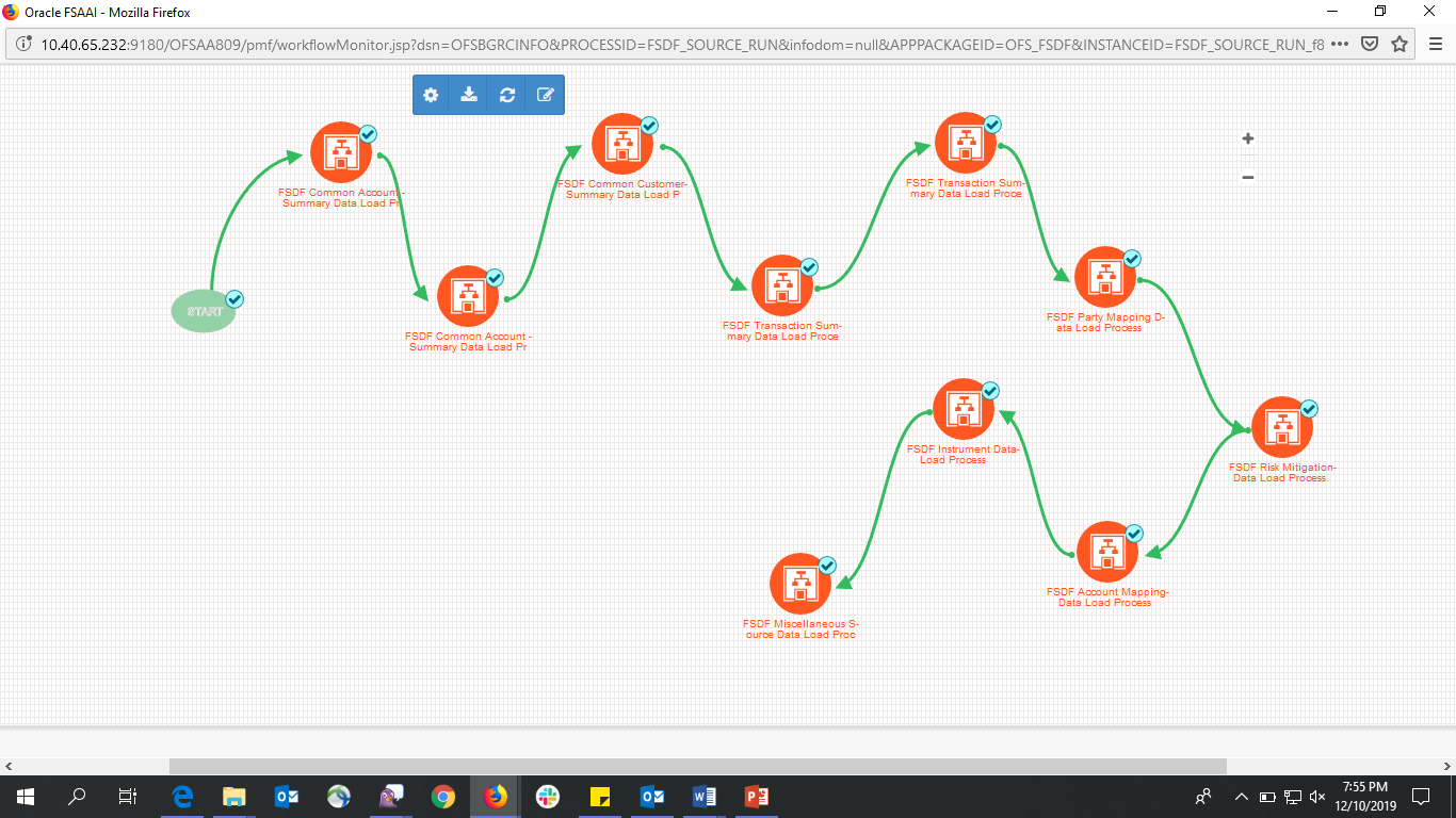 icon
at each Sub Pipeline indicates that the Run execution is successful.
icon
at each Sub Pipeline indicates that the Run execution is successful.
NOTE:
The  icon
at each Sub Pipeline indicates that the Run execution is unsuccessful.
icon
at each Sub Pipeline indicates that the Run execution is unsuccessful.
Figure 79: Run Pipeline Process Flow Diagram

You can access the execution logs to verify the details of the Run.
To verify the execution log, follow these steps:
1. In the
Process
Monitor window, click the required process flow ID. The process
flow diagram is displayed in a new window. Hover on the required Sub Pipeline.
Four icons appear. Click the log  Icon.
Icon.
Figure 80: Sub Pipeline

2. The Execution Logs window is displayed. Click the required metadata to verify the execution log.
Figure 81: Execution Logs

3. The Activity window is displayed. Click Execution Log.
Figure 82: Activity Logs

4. The Run execution log details are listed in a separate window.
Alternatively, to verify the execution logs, click the
icon
in the Process flow diagram window. The log details of the Run execution
are displayed in a new window.
Figure 83: Run Execution Logs

For detailed information about the complete functioning of the PMF, see the Process Modelling Framework Orchestration Guide.