HA Node Connections
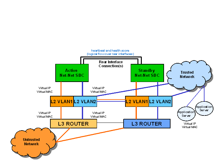
To use HA, you must establish Layer 2 and Layer 3 networks that interconnect two Oracle Communications Session Border Controllers and support HA with the required physical network connections. The basic network set-up in the following diagram shows an HA node deployment where each system is connected to its own Layer 2 switch. This set-up provides a measure of added redundancy in the event that one of the switches fails.
Here, the active system is using the virtual MAC and IP addresses.

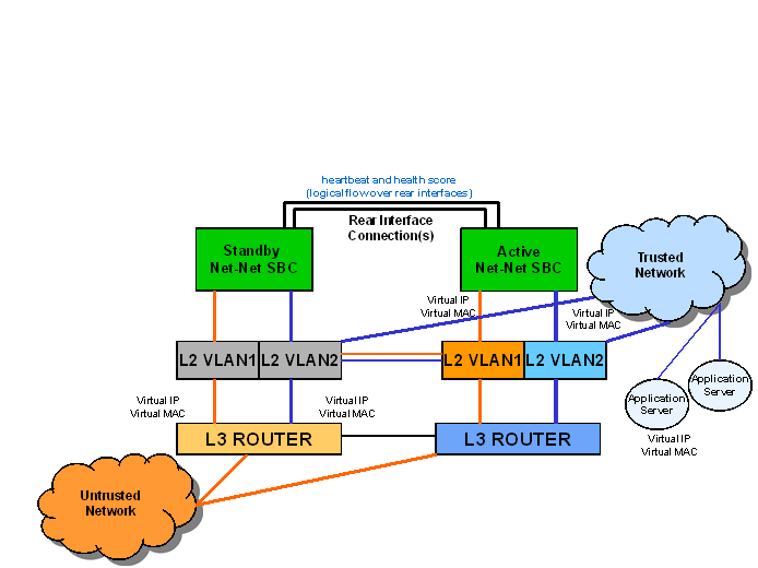
In the second diagram, the same network is shown with the HA node having experienced a switchover. The previously standby Oracle Communications Session Border Controller has taken over the active role in the HA node and is using the virtual IP and MAC addresses.

Note:
Switches should never be in master-slave mode. If they are, HA will not work correctly.The following are hardware set-up and location considerations for placing an HA Node:
- You must set up each Oracle Communications Session Border Controller according to the requirements and safety precautions set out in the Oracle Communications System Hardware Installation Guide.
- Each Oracle Communications Session Border Controller’s media interfaces must be connected to the same switches (or other network entities), as shown in the diagram above.
- The length of the shielded crossover 10/100 category 5 Ethernet cable that connects the Oracle Communications Session Border Controllers from the rear interfaces must be able to reach from the configured rear interface on one Oracle Communications Session Border Controller to the configured rear interface on the other.
HA nodes use Oraclerder element redundancy protocol for its tasks. This protocol uses a connection between the rear interfaces of two Oracle Communications Session Border Controllers to checkpoint the following information: health, state, media flow, signaling, and configuration.
We recommend that you use shielded category 5 (RJ45) crossover cables for all 10/100 Ethernet connections used for HA.
You can set up either single or multiple rear interface support for your HA node. For single interface support, one cable connects the two Oracle Communications Session Border Controllers; for multiple interface support, two cables are used. However, the software configurations for each type of connection mode are different.
When you make these connections, do not use port 0 (wancom0) on the rear interface of the Oracle Communications Session Border Controller chassis; that port should only be used for Oracle Communications Session Border Controller management. Instead, use ports 1 and 2 (wancom1 and wancom2).
To cable Oracle Communications Session Border Controllers using single rear interface support:
Virtual MAC Addresses
In order to create the HA node, you need to create virtual MAC addresses for the media interfaces. You enter these addresses in virtual MAC address parameters for phy-interface configurations where the operation type for the interface is media.
The HA node uses shared virtual MAC (media access control) and virtual IP addresses for the media interfaces. When there is a switchover, the standby Oracle Communications Session Border Controller sends out an ARP message using the virtual MAC address, establishing that MAC on another physical port within the Ethernet switch. Virtual MAC addresses are actually unused MAC addresses that based on the Oracle Communications Session Border Controller’s root MAC address.
The MAC address is a hardware address that uniquely identifies each Oracle Communications Session Border Controller. Given that, the virtual MAC address you configure allows the HA node to appear as a single system from the perspective of other network devices. To the upstream router, the MAC and IP are still alive, meaning that existing sessions continue uninterrupted through the standby Oracle Communications Session Border Controller.
Depending on the type of physical layer cards you have installed, you can create MAC addresses as follows: Four Ethernet (MAC) address for each configured four-port GigE physical interface card.
Virtual MAC Addresses for VNFs
Virtual Network Functions (VNFs) rely on their hypervisor environment for MAC address establishment, advertisement and resolution. As such, you cannot derive these addresses using the same method as you do for Acme platforms. For VNFs, Oracle recommends establishing private MAC addressing for virtual MAC address configuration.
To support HA, you configure virtual Ethernet (MAC) address MAC addresses based on the Burned In Addresses (BIA) of the media interfaces. To determine what the virtual MAC addresses should be, you first identify a BIA and then calculate the virtual MACs based on that.
To define the virtual addresses you need to configure for each interface:
- Identify the base MAC of eth0/wancom0 physical interface using the show interfaces command. For example, in the following display, you can see the base MAC is 00:50:56:C0:00:08:
eth(unit number 0):
Flags: (0x78843) UP BROADCAST MULTICAST ARP RUNNING INET_UP
Type: ETHERNET_CSMACD
inet: 111.22.0.123
Broadcast address: 111.22.255.255
Netmask 0xffff0000 Subnetmask 0xffff0000
Ethernet address is 00:50:56:C0:00:08
- Set the bottom nibble of the first byte to 2 to define the address as locally administered.
- Set the top nibble of the first byte to 0 and increment it for each interface.
For example, using the base-MAC for eth0, 00:50:56:C0:00:08, you assign the virtual addresses as follows:
- First media interface virtual MAC = 02:50:56:C0:00:08
- Second media interface virtual MAC = 12:50:56:C0:00:08
- Third media interface virtual MAC = 22:50:56:C0:00:08
- Forth media interface virtual MAC = 32:50:56:C0:00:08


