TSCF Overview
Tunnel Session Management (TSM) is based upon an existing 3rd Generation Partnership Project (3GPP) Technical Requirement, TR 33.8de V0.1.3 (2012-05) that seeks to define a standardized approach for overcoming non-IMS aware firewall issues. Within the 3GPP, TSM is referred to as Tunneled Services Control Function or TSCF. Oracle uses the 3GPP terminology: TSCF.
TSCF improves firewall traversal for over-the-top (OTT) Voice-over-IP (VoIP) applications, and reduces the dependency on SIP/TLS and SRTP by encrypting access-side VoIP within standardized Virtual Private Network (VPN) tunnels. As calls or sessions traverse a TSCF tunnel, the Oracle Communications Tunneled Session Controller forwards all SIP and RTP traffic from within the TSCF tunnel to appropriate servers or gateways within the secure network core. Operating in a TSM topology, the SBC provides exceptional tunnel performance and capacity, as well as optional high availability (HA), DoS protection and tunnel redundancy that improves audio quality in lossy networks.
As implemented by Oracle Communications, TSM/TSCF terminology includes:
- TSC client—Sometimes referred to as a Tunneled Service Element (TSE). It facilitates TSCF tunnel creation and management within client applications residing on network elements.
- TSC server—The SBC that is used to terminate TSC tunnels.
- Tunnel Session Management (TSM)— The overall solution that covers both the TSC Server and TSC Client.
- TSCF (Tunneled Services Control Function)—The actual function that runs on the SBC. TSCF is often used in the naming of the ACLI configuration and management objects.
A TSC client runs within client applications residing on network elements — for example: workstations, laptops, tablets and mobile devices (Android, iPhone, Windows, or iPad). Oracle provides a software development kit (SDK) that facilitates TSCF tunnel creation and management. Refer to the companion document, the TSE SDK Guide, or to the SDK on-line Help system for information on client-side programming, and to access reference applications that provide client-specific coding examples for supported operating systems.
To deploy TSC clients, customers and 3rd party Independent Software Vendors (ISVs) need to link the open source TSC client libraries with their applications, which can then initiate and establish SSL VPNs (TLS or DTLS) to the TSC server.
In contrast to a TSC client, a TSC server resides on the Oracle Communications Session Boarder Controller (OCSBC), and provides server-side functions that accept, establish, and manage tunnel connections between remote TSC-client-enabled applications and core Proxy-Call Session Control Function and SIP proxies (P-CSCFs/SIP proxies). The following illustration shows various ways in which TSC clients can be deployed across different network segments (WiFi, LAN, WAN, LTE) and interface with common network elements (firewalls, HTTP proxies, and radio access network equipment).
Figure 21-1 TSM /TSCF Topologies

TSCF Entitlements
In order to use correct feature of TSCF, the below entitlement commands need to be used to apply correct setup.
If this is your first time use the TSCF entitlement, you first need to setup product as below.
ORACLE# setup entitlements
Product not initialized; Please use 'setup product'

ORACLE# setup product

--------------------------------------------------------------
WARNING:
Alteration of product alone or in conjunction with entitlement
changes will not be complete until system reboot

Last Modified
--------------------------------------------------------------
1 : Product       : Uninitialized

Enter 1 to modify, d' to display, 's' to save, 'q' to exit. [s]: 1

  Product
    1 - Session Border Controller
    2 - Session Router - Session Stateful
    3 - Session Router - Transaction Stateful
    4 - Peering Session Border Controller
  Enter choice     :

  Select either 1 or 4 above depending other features you are using.
Use the show entitlements command to display your TSCF enabled status.
ORACLE# show entitlements
Provisioned Entitlements:
-------------------------
Session Border Controller Base    : enabled
Session Capacity                  : 32000            <---- This setup also
  Accounting                      : enabled																used for TSCF
  IPv4 - IPv6 Interworking        : enabled
  IWF (SIP-H323)                  : enabled
  Load Balancing                  : enabled
  Policy Server                   : enabled
  Quality of Service              : enabled
  Routing                         : enabled
  SIPREC Session Recording        : enabled
Admin Security with ACP/NNC       :
IMS-AKA Endpoints                 : 0
IPSec Trunking Sessions           : 0
MSRP B2BUA Sessions               : 0
SRTP Sessions                     : 0
TSCF Tunnels                      : 10000             <---- Non-zero to
																																																												enable TSCF
																																																												entitlement.
Use setup entitlements to change entitlements for your TSCF enabled status, as below.
ORACLE# setup entitlements
 -----------------------------------------------------
Entitlements for Session Border Controller
Last Modified: 2015-05-19 22:07:05
-----------------------------------------------------
 1 : Session Capacity                        : 32000
 2 :   Accounting                            : enabled
 3 :   IPv4 - IPv6 Interworking              : enabled
 4 :   IWF (SIP-H323)                        : enabled
 5 :   Load Balancing                        : enabled
 6 :   Policy Server                         : enabled
 7 :   Quality of Service                    : enabled
 8 :   Routing                               : enabled
 9 :   SIPREC Session Recording              : enabled
 10: Admin Security with ACP/NNC             :
 11: IMS-AKA Endpoints                       : 0
 12: IPSec Trunking Sessions                 : 0
 13: MSRP B2BUA Sessions                     : 0
 14: SRTP Sessions                           : 0
 15: TSCF Tunnels                            : 10000

Enter 1 - 15 to modify, d' to display, 's' to save, 'q' to exit. [s]:
To disable TSCF entitlement feature, set TSCF Tunnels to zero.
To enable TSCF Decomposed feature only, set above Session Capacity to zero.
The above setting is for TSCF Coupling or TSCF SBC Enabled status.
Supported Encryption for TSM
- DTLS 1.0
- TLSv1.0, TLSv1.1, TLSv1.2
Deployment Models
Based on local network topology and requirements, TSM service can be deployed in two ways:
- Decomposed model
- Combined model
Decomposed Model
The decomposed model provides TSC functionality on an Oracle server (for example, a Multiprotocol Security Gateway or a generic SBC). Regardless of the supporting platform, the TSC server acts as a pass through server, using a data-flow (refer to TSCF Data Flow Configuration) to forward all tunnel traffic to a pre-determined IP address. In the simplest topology, this address would access a gateway providing the protocol support required to route the previously tunneled traffic to its ultimate destination. Alternatively, the data-flow could direct tunneled traffic to another SBC that provides P-CSCF (Proxy-Call Session Control Function) services as shown in the following illustration.
Figure 21-2 Decomposed Model
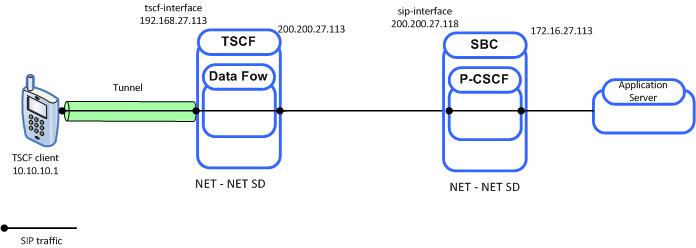
Within this decomposed TSC server:
- 192.168.27.113 provides a TSCF interface to the access realm (refer to TSCF Interface Configuration for procedural details)
- The TSCF interface has an assigned address pool (refer to TSCF Address Pool Configuration for procedural details) that provides a contiguous range of tunnel addresses (for example, 10.10.10.1 available to TSC clients
- The TSCF address pool has an assigned data-flow (refer to TSCF Data Flow Configuration for procedural details) that specifies a static route to the core realm
- 200.200.27.113 provides a SIP interface that provides transit to the core realm
Within the P-CSCF server:
- 200.200.27.18 provides a SIP interface serving the core realm
- 172.16.27.113 provides an interface to a SIP application server
Decomposed packet flow can be summarized as follows:
- The TSC client connects to the TSC server at 192.168.27.113
- Assuming client authentication succeeds, the TSC server accepts connection and assigns the TSC client a tunnel address (10.10.0.1)
- Using the tunnel, the TSC client sends a SIP INVITE from 10.10.0.1 to a remote peer
- Using the data-flow, the TSC server forwards the INVITE to the core realm (200.200.27.118)
- The P-CSCF forwards the INVITE to the SIP application server
Combined Model
The combined model involves deploying both the TSCF and P-CSCF on the same Oracle SBC. With this model, the TSCF can be configured to pass SIP traffic to the co-located P-CSCF (thus providing standard SIP processing), and to use a data-flow to pass all non-SIP traffic to a designated destination, most often a gateway that provides the protocol support required to route the previously tunneled data traffic to its ultimate destination.
Figure 21-3 Combined Model - Standard Processing
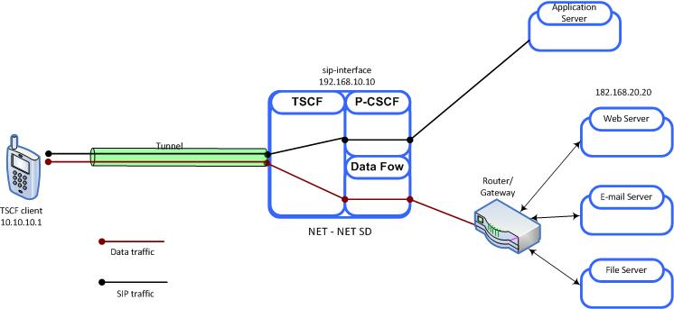
Within this combined TSC server:
- 192.168.10.10 (a SIP interface) provides a TSCF interface to the access realm (refer to TSCF Interface Configuration for procedural details)
- SIP signalling traffic received from a tunnel endpoint (and explicitly addressed to 192.168.10.10) is directed to an appropriate P-CSCF process for forwarding to a generic or specialized SIP application server
- The TSCF interface has an assigned address pool (refer to TSCF Address Pool Configuration for procedural details) that provides a contiguous range of tunnel addresses (for example, 10.10.1) available to TSC clients
- The TSCF address pool has an assigned data-flow (refer to TSCF Data Flow Configuration for procedural details) that specifies a static route to a router/gateway; any data traffic received from a tunnel endpoint is passed through to the gateway
The following figure illustrates traffic pass-through within the Combined model.
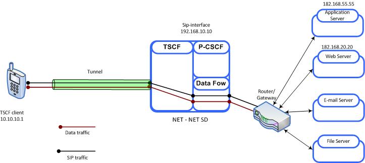
Within this combined TSC server:
- 192.168.10.10 (a SIP interface) provides a TSCF interface to the access realm (refer to TSCF Interface Configuration for procedural details)
- The tunnel client sends SIP messages to 182.168.55.55 (a SIP interface not resident on the Oracle SBC)
- In this case, all traffic is subject to the data-flow, which directs both SIP signalling and media streams to a gateway for routing to the destination IP address
Figure 21-4 Combined Model - Pass-Through Processing
Tunnel Establishment
Tunnel creation is initiated by the client application that first establishes a TLS and/or DTLS tunnel between the TSC client and the TSC server. Tunnel creation is completed with a single exchange of configuration data accomplished by a TSC client request and TSC server response. Refer to the TSE SDK Guide for detailed information on tunnel set-up procedures.
The following illustration briefly explains the IP addresses used during TSM tunnel establishment and operation.
Figure 21-5 TSM Tunnel Address Structure
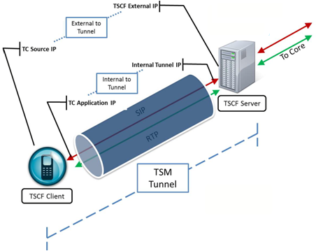
- TSCF External IP—This public IP address is visible to any endpoint; TSC client requests for tunnel establishment are directed to this address (refer to TSCF Interface Configuration for procedural details).
- TC source IP—This public IP address identifies either the source address of the TSC client in its respective access network, or the IP address of an intervening proxy, firewall, or NAT device.
- Internal Tunnel IP—This private address will be assigned to the TSC client (assuming authentication is successful) from a configured pool of IP addresses on the TSC server. Refer to TSCF Address Pool Configuration for procedural details.
- TC Application IP—This private IP address identifies a specific application (SIP/RTP/etc.) at the TSC client site.
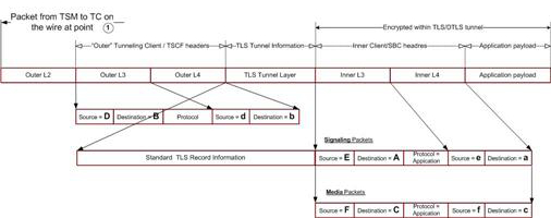
All packets between the client application on the TSC client and the TSC server are comprised of inner and outer parts separated by a TLS header. All data after the TLS header is encrypted.
- Outer headers contain TSC client and TSC server addresses
- Inner headers contain application and P-CSCF addresses
- Payload packets carry application data between the TSC client and the TSC server
- Control payloads support tunnel management and configuration activities such as the assignment of a TSC client inner IP address, and the exchange of keepalive messages
The following two illustrations depict simplified packet formats.
Figure 21-6 Data Traffic Packet Structure

Figure 21-7 Control Traffic Packet Structure

The following illustrations provide a more detailed view of packet structure and addressing. The first figure provides a network reference model.
Figure 21-8 Reference Model
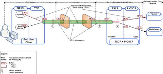
These two figures show a client-initiated and a server-initiated packet with sample addresses.
Figure 21-9 TSC Client to TSC Server
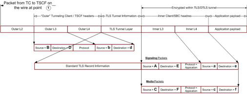
Figure 21-10 TSC Server to TSC Client
Tunnel Redundancy
The ability to establish parallel, redundant tunnels improves media quality under adverse network packet loss conditions (defined as packet loss within the 5% to 25% range). As the name implies, tunnel redundancy creates secondary TSCF tunnels that replicate signaling and media transport between the TSC client and the TSC server.
Tunnel redundancy is one of the assigned services, along with ddt, server-keepalive, and sip, that can be enabled or disabled on a TSCF interface; by default, tunnel redundancy is disabled. This service is enabled by including the string redundancy in the comma-separated assigned-services list (refer to TSCF Interface Configuration for procedural details).
With tunnel redundancy enabled, as packets traverse networks and encounter packet loss and drop, the TSC client and TSC server choose the most available and timely packet from the duplicative tunnels. Within redundant tunnels, packets are slightly offset (as shown in the following figure), so as a gateway or other intervening network elements drop packets, the same packet that was dropped in one tunnel remains in another tunnel. When the packets reach their destination in the core, or on the client, the media stream is reformed as if packet loss never happened.
Figure 21-11 Tunnel Redundancy

Tunnel redundancy works in concert with RTP redundancy and packet loss concealment algorithms that are often implemented by advanced variable bit rate codecs such as SPEEX, SILK or iSAC. Like RTP redundancy, defined in RFC 6354, Forward Shifted RTP Redundancy Payload Support, tunnel redundancy does increase bandwidth usage by replicating signaling and media but also maximizes the chances of packet delivery. In addition to packet loss, tunnel redundancy can also mitigate the effects of jitter (variable packet delay), a common network impairment that can result in significant speech quality degradation.
A TSC client can initiate tunnel redundancy at call establishment or, in response to current network conditions, at any time within an established call session. Depending on the transport protocol (TCP or UDP) a TSC client can request one of three available tunnel redundancy modes:
- TLS/TCP Load Balancing
- TLS Fan-Out
- DTLS/UDP Redundancy
TLS/TCP Load Balancing
TLS/TCP load balancing mode is based on parallel, redundant tunnels. Both the TSC client and the TSC server send RTC encapsulated packets on one tunnel at a time. Each subsequent packet is sent on the next tunnel in a circular fashion. The following illustration shows packet transmission over time with packet transmission balanced over a main tunnel and two redundant tunnels.
Figure 21-12 Redundancy — TLS/TCP Load Balancing

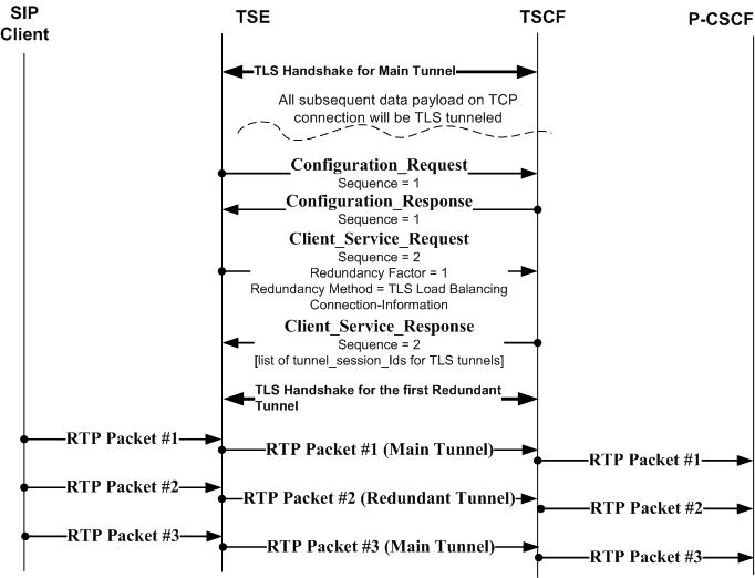
This illustration provides a sample message flow for TLS/TCP load balancing negotiation.
Figure 21-13 TLS/TCP Load Balancing Message Flow
TLS TCP Fan-Out
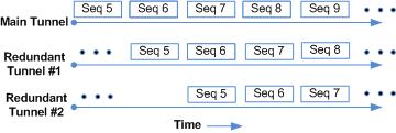
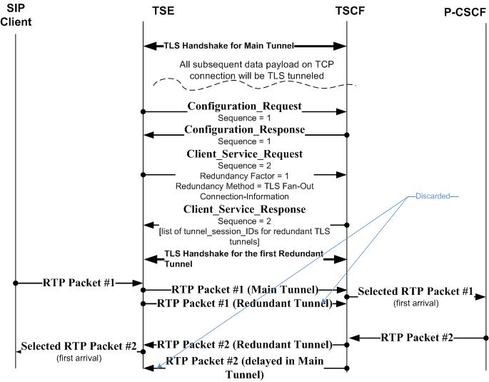
TLS/TCP fan-out mode is also based on redundant parallel tunnels. Both the TSC client and the TSC server send RTC encapsulated packets on the main tunnel. Additionally both the client and server send the same packet on each redundant tunnel in a time-staggered fashion. The following illustration shows packet fan-out over time with a main tunnel and two redundant tunnels.
Figure 21-14 Redundancy — TLS/TCP Fan-Out Load Balancing
This illustration provides a sample message flow for TLS/TCP fan-out.
Figure 21-15 TLS/TCP Fan-Out Load Balancing Message Flow
DTLS UDP Redundancy
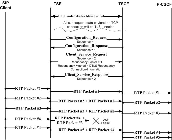
DTLS/UDP redundancy mode, unlike TLS/TCP load balancing and TLS/TCP redundancy modes, does not establish redundant parallel tunnels between the TSC client and TSC server. Instead, both the client and server exchange frames of RTC encapsulated packets. Each frame contains a new packet and some number of sequential, previously sent packets. The following illustration shows DTLS/UDP redundancy over time.
Figure 21-16 Redundancy — DTLS/UDP Redundancy

This illustration provides a sample message flow for DTLS/UDP redundancy.
Figure 21-17 DTLS/IDP Load Balancing Message Flow
Denial of Service
Denial of Service (DoS) protection provides access control and bandwidth control for tunneled traffic.
Because tunneled traffic is confined to a small number of well-defined ETC-based ports, traffic processing can be streamlined. Incoming traffic is directed to one of two pipes, each supported by dedicated queues, for transmission toward the network core. A larger pipe provides maximal bandwidth for trusted tunnel endpoints, while a smaller pipe provides minimal bandwidth for untrusted tunnel endpoints.
Tunnels can be promoted to the trusted level, or demoted to the untrusted level.
Initially all incoming traffic is treated as untrusted and directed to the untrusted pipe. When the TLS handshake is successfully completed (meaning that the two peers have mutually authenticated) the tunnel transitions to the trusted state. The tunnel remains in the trusted state until the expiration of the tunnel persistence timer, as described in TSCF Global Configuration.
Server-Initiated Keepalive
For some TSC client devices, such as IPhones or iPads, operating system constraints can prevent the transmission of timely keepalive messages required to refresh an existing TSCF tunnel connection or to maintain current NAT bindings. To address this problem the TSC server can be configured to issue periodic server-initiated keepalive (SIK) messages to clients who require such service.
SIK is one of the assigned services, along with ddt, redundancy, and sip, that can be enabled or disabled on a TSCF interface; by default, SIK is disabled. SIK is enabled by including the string server-keepalive in the comma-separated assigned-services list (refer to TSCF Interface Configuration for procedural details).
SIK services are provided only in response to a TSC client request. The client requests SIK services during the configuration process. Upon receiving such a request, the TSC server checks the status of SIK on the interface on which the service request was received. If SIK is enabled, the request is accepted; if SIK is disabled (the default state), the request is denied.
Dynamic Datagram Tunneling
Dynamic datagram tunneling (DDT) provides parallel stream-based (TCP/TLS) and datagram-based (UDP/DTLS) tunnels to address problems/challenges in delivering Real-Time Protocol (RTP) media over a connection-oriented, reliable TCP transport. With DDT enabled, the TSC client and TSC server negotiate a single secure, persistent, stream-based tunnel, used for SIP signaling and tunnel maintenance, as well as a series of dynamic datagram-based tunnels used for RTP media transport.
With DDT enabled the TSC server assigns the same inner tunnel address to both the stream-based and datagram-based tunnels. The initial datagram-based tunnel provides a template for subsequent tunnels created to service pending RTP packets. Each tunnel is configured in exactly the same manner as the initial tunnel, save for the tunnel ID, which is unique for each tunnel instance.
Dynamic datagram tunneling is one of the assigned services, along with redundancy, server-keepalive, and sip, that can be enabled or disabled on a TSCF interface; by default, dynamic datagram tunneling is disabled. The service is enabled by including the string ddt in the comma-separated assigned-services list (refer to TSCF Interface Configuration for procedural details). DDT configuration has some unique requirements as listed below:
- assigned-services MUST be set to sip,ddt
- a TLS/TCP port must be configured on the TSCF interface
- a DTLS/UDP port, using the same IP address and port number as assigned to the TLS/TCP port must be configured on the same TSCF interface
Dynamic datagram tunneling service is provided only in response to a TSC client request. The client requests this service during the configuration process. Upon receiving such a request, the TSC server checks the status of dynamic datagram tunneling on the interface on which the service request was received. If the service is enabled, the request is accepted; if the service is disabled (the default state), the request is denied.
Tunnel Restoration and High Availability
Datagram Transport Layer Security (DTLS) and Dynamic Datagram Tunnels (DDT) support disruption-free traffic flow during High Availability (HA) failover.
During normal operations, the active member of the HA pair synchronizes certain DTLS tunnel details with its stand-by partner to include internal IP addresses, tunnel identifiers, cryptographic materials, and additional DTLS context information. DTLS tunnels carry the media stream. Upon synchronization, the stand-by member populates the DTLS stack with the received data, and creates DTLS tunnels in a quasi-active state — such tunnels do not actually process packets. If and when HA handover occurs, the presence of the traffic-ready DTLS tunnels mitigates against disruption of the media stream.
When an HA pair experiences a failover (or in the event of any disconnect), TSC clients have a grace period (defined by the tunnel-persistence-time parameter) to recognize the failure and re-connect using the same tunnel. If clients react in a timely fashion, the newly active system allocates the same TSCF tunnel identifier and IP address.
A similar, although not identical approach, is used in DDT environments.
DDT tunnel restoration proceeds as follows:
- The active member updates the DTLS tunnels, which carry the media streams with augmented contextual information as described above.
- In the event of HA failover, the TLS tunnels, which carry control traffic and signalling, continue in the persistent state, and remain in that state until:
- the stand-by transitions to the active role, and
- the client re-connects
Only after these two conditions are met does the TLS tunnel transition to the active state.
- If the TSC client requests restoration of the TLS tunnel before the persistent timer expires, the server updates the newly established tunnel with DDT-related information.
- If the TSC client fails to request restoration of the TLS tunnel before the persistent timer expires, the server deletes both the TLS tunnel and the associated DTLS tunnel.
The show tscf statistics, show tscf tunnel all, and show tscf tunnel detailed ACLI commands all provide various counts of HA tunnel restoration operations.
Nagle Algorithm Control
Like DDT, Nagle algorithm control can provide an alternative method of improving delivery of RTP media over a TCP/TLS transport.
The Nagle algorithm is defined in RFC 896, Congestion Control in IP/TCP Networks. The algorithm is designed to improve the efficiency of IP/TCP networks by reducing the number of transmitted packets. With the Nagle algorithm enabled, the transmitting device buffers any outgoing data until all previously sent data has been acknowledged, or until the size of the buffered data exceeds a full packet of output.
The Nagle algorithm is enabled by default, and is subject to user control.
Users can:
- Specify a TSCF-Interface-specific default value (enable | disable) that determines the state of the Nagle algorithm on that TSCF interface
- Override the default algorithm state on a specified tunnel
Override requests are included in the Application Payload as shown in TSC Client to TSC Server.
The show tscf statistics, show tscf tunnel all, show tscf tunnel detailed, and show tscf tunnel <tunnel-id> verbose ACLI commands all provide various counts of algorithm operations.
Refer to TSCF Interface Configuration for configuration details.
Online Certificate Status Protocol
The Online Certificate Status Protocol (OCSP) is defined in RFC 2560, X.509 Internet Public Key Infrastructure Online Certificate Status Protocol - OCSP. The protocol enables users to determine the revocation state of a specific certificate.
RFC 2560 specifies the data exchanged between an OCSP client, in the current implementation the TSCF, and an OCSP responder, the Certification Authority (CA), or its delegate that issued the certificate to be verified. An OCSP client issues a request to an OCSP responder and suspends acceptance of the certificate in question until the responder replies with a certificate status.
If the OCSP responder returns a status of good, the certificate is accepted and authentication succeeds. If the OCSP responder returns a status other than good, the certificate is rejected and authentication fails.
Certificate status is reported as:
- Good—Indicates a positive response to the status inquiry. At a minimum, a positive response indicates that the certificate is not revoked, but does not necessarily mean that the certificate was ever issued or that the time at which the response was produced is within the certificate’s validity period.
- Revoked—Indicates a negative response to the status inquiry. The certificate has been revoked, either permanently or temporarily.
- Unknown—Indicates a negative response to the status inquiry. The responder cannot identify the certificate.
When authentication of remote TSC clients is certificate-based, you can enable OCSP on TSCF ports to verify certificate status. The TSCF/OCSP responder connection must be secured by the TLS protocol.
OCSP Request Processing
With OCSP enabled, the TSCF checks certificate revocation during the TLS handshake. After receiving the client certificate, the TSCF sends an OCSP request to a responder, and pauses the TLS handshake. Assuming a good response, the TSCF resumes the handshake, and establishes a TLS tunnel once the handshake is successfully ended. If the response is revoked or unknown, the handshake fails, and TSCF does not establish a tunnel.
The TSCF places OCSP requests in an outbound queue, and maintains a list of outstanding requests, which is updated upon the receipt of OCSP responses. When the TSCF receives a new request, it checks the certificate serial number, and possibly the identity of the issuing CA, against the list. If the request matches a list entry, TSCF ignores the request, and awaits the response to the outstanding request; if the request does not match a list entry, TSCF sends a new OCSP request to a responder.
OCSP Certificate Verification
Providing OCSP services requires the creation of a secure TLS connection between a TSCF port and one or more OCSP responders.
This configuration is a three-step process:
- Create one or more certificate-status-profiles. Each certificate-status-profile provides the information and cryptographic resources required to access a single OCSP responder.
- Assign one or more certificate-status-profiles to a tls-profile. This tls-profile enables OCSP services and provides a list of one or more OCSP responders.
- Assign the tls-profile to a TSCF port to enable OCSP service on that port.
For details on using the ACLI to configure OCSP-based certificate verification services, see TSCF OCSP Configuration.
TSM Security Traversing Gateway Mode
The Security Traversing Gateway (STG) is a specific implementation of the TSCF, and is responsible for maintaining tunnels between the client and server, and handles encapsulation and de-encapsulation for IMS service data. Tunnel types include TLS and DTLS tunnels.
To deploy TSC clients (such as softphones, SIP-enabled iOS/Android applications or contact center agent applications), customers and 3rd party ISVs need to incorporate the TSM's open source software libraries (TSC or STG clients) into their applications which will establish SSL connections (TLS or DTLS) to the TSC server. If the STG is to be implemented, you must use the Oracle Software Developer Kit (SDK), release 1.4 or above.
TSC client sends encapsulation data to the STG through the tunnel, and the STG decrypts data and forwards to the SBC, then SBC will do IMS business data handling. When CM-IMS core network tries to send data to the client using security tunnel mode, the SBC will send data to STG, which will do data encapsulation and forward to client via security tunnels.
Note:
The STG feature is not intended for all customer use. Consult your Oracle representative to understand the circumstances indicating the use of this feature.STG Supported Platforms
These are the platforms supported for the initial release of the Security Traversing Gateway (STG):
- Acme Packet 4600
- Acme Packet 6100
- Acme Packet 6300
STG Prerequisites
In order to activate STG Mode, you must first fulfill the following prerequisites:
- Configure at least one TSE built with SDK version 1.4 and above
- Provision a TSCF Interface
Note:
Refer to "TSCF Interface Configuration" for details.The default TSM parameters are the same as the default parameters of a TSE configured with SDK version 1.4.
STG Keep-Alive Mechanism
Keep Alive Request Command Messages (CMs) are sent periodically at 66% of the keep alive interval negotiated through Configuration Request and Configuration Response CMs. Configuration Request CMs are sent by either the TSE or TSM and Configuration Response CMs are sent by the either the TSE or TSM. If Keep Alive Request CMs are not received within the configured keep alive interval, the tunnel transport is terminated and tunnel renegotiation is started. If the keep alive interval is not negotiated correctly because the Configuration Response CM doesn't include it, a default value is used. The Keep Alive Request CMs are transmitted by both of the ends of the tunnel once, so if the tunnel transport packet loss is present, premature tunnel termination is possible.
STG Configuration Resume
If contact is lost between the TSM and the TSE during configuration, the tunnel goes into TSM persistence. The TSE transmits a Configuration Resume CM with the tunnel ID (TID), to which the TSE responds with a Configuration Resume Response, also with the TID. This mechanism is used instead of a Tunnel Resume mechanism.
Blocking TSCF Inter-client Communication
To deploy TSC clients (such as softphones, SIP-enabled iOS/Android applications or contact center agent applications), customers and 3rd party ISVs need to incorporate the TSM's open source software libraries (TSC clients) into their applications which will establish SSL connections (TLS or DTLS) to the TSC server. If the inter-client-blocking is to be implemented, you must use the Oracle Software Developer Kit (SDK), release 1.4 or above.
TSC client sends encapsulated data through the tunnel, and the TSC server decrypts data and forwards to the SBC, then SBC will do IMS business data handling. When CM-IMS core network tries to send data to the client using security tunnel mode, the SBC will send data to TSC server, which will do data encapsulation and forward to client via security tunnels.
The inter-client-block assigned service is a specific implementation of the TSCF, and is responsible for preventing clients using TSCF from communicating directly with other TSCF clients. Without the use of this assigned-services mode, any TSCF client could directly send traffic to other TSCF clients on any realm on the TSCF server. The blocking of this type of inter-client communication capability enhances security.
With inter-client-block configured, the TSCF server will check the destination address of every de-tunneled packet and compare it against all the configured TSCF address pools that are in use on the system. If the destination address falls in the range of configured TSCF address pools, then the packet will be dropped.


