2 Configuring the Linux System for ACSLS HA
This chapter describes how to prepare the Linux system to support ACSLS HA.
Topics include:
Configuring /etc/hosts
Your /etc/hosts file on each node must contain entries for the local host, the two Linux node names, their IP addresses and the logical host. You can create this file on both nodes even if these IP addresses are not yet configured.
Define the local host 127.0.0.1 as shown in the example below.
The ”public network interface” is that which you defined when you first installed the operating system. In the following example, it is mapped to physical device NET0 (logical device eno1).
The /etc/hosts file must contain entries for the ACSLS HA interconnects as shown below. They must be named localnode and remotenode. You will configure the actual interfaces later in the configuration process. For now, add them to the /etc/hosts file.
Example /etc/hosts file - Node 1:
# localhost
127.0.0.1   localhost localhost.localdomain localhost4
localhost4.localdomain4
::1         localhost localhost.localdomainlocalhost6
localhost6.localdomain6

# Public Network
10.80.25.113    hostname1.Domain.com      hostname1
# ACSLS-HA Logical Host
10.80.25.65     hostname1.Domain.com      hostname1
# ACSLS-HA Interconnects
192.168.84.1    localnode
192.168.84.2    remotenode
Example /etc/hosts file - Node 2:
# localhost
127.0.0.1   localhost localhost.localdomain localhost4
localhost4.localdomain4
::1         localhost localhost.localdomainlocalhost6
localhost6.localdomain6

# Public Network
10.80.25.131    hostname2.Domain.com      hostname2
# ACSLS-HA Logical Host
10.80.25.65     hostname2.Domain.com      hostname2
# ACSLS-HA Interconnects
192.168.84.1    remotenode
192.168.84.2    localnode
Multipath Bonded Network Configuration
Redundancy is the overall scheme for high-availability computing. Redundancy applies not only to the servers, but to each communication interface on each server. For the public interface, use Internet Protocol Bonding on Linux. Internet Protocol Bonding provides instant NIC recovery for failing network communications without the need for a general system failover. For the library interface, this means using a dual TCP/IP connection with two network interfaces across two independent routes. If any element in one route should fail, ACSLS continues to communicate over the alternate interface. Note that if both paths to the library interfaces fail at the same time, ACSLS HA will not fail over to the other node. This is to protect the integrity of other ACSs that may also be controlled by the instance of ACSLS that ACSLS HA is controlling.
ACSLS HA requires redundant network connections for the following:
-
Public and client communications
-
Library communications
-
Private intra-node cluster communications
-
NFS communications
Port Mapping
Figure 2-1 shows eight Ethernet ports on each server, accessible from two separate Network Interface Controllers (four ports on each). A total of eight ports on each node are used.
Connect cables for eight network interface ports:
-
One cable for ACSLS-HA Logical Host connection for client access.
-
Two cables for Library communications
-
Two cables for direct Intra-node communications
-
Two cables for NFS communications
-
One cable for Public administration access.
Use Figure 2-1 as a guide.
Note:
-
Each port of each pair for the direct intra-node and NFS connections must reside on a different network interface card (NIC). This ensures that each NIC is not a single point of failure when the connections are bonded.
-
The naming conventions used for the ports (eno1, ens2fo) in this guide may differ from your environment if your servers are of a different brand or model than used by Oracle and/or if you have installed external ethernet cards that use a different naming convention. If they differ then you will have adjust your configuration commands accordingly. It is strongly recommended that your ethernet cards and motherboard ports are named (device name) exactly the same.
-
The IP addresses, bondings, and other networking configuration parameters in the examples provided in this publication coincide with Figure 2-1 and are used as if you are configuring the environment in this diagram. You must adjust accordingly for the private routes, IP addresses and other networking parameters in your environment.
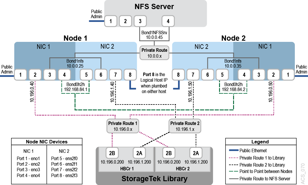
Figure 2-1 shows two Network interface cards with four ports each.
-
Each network device (port) has an associated configuration file named
ifcfg-interfacein the/etc/sysconfig/network-scriptsdirectory, whereX-interfaceis the name of the interface. The names of your ports may differ from this if you are using a different server brand. You must have identical ethernet cards installed in each system. -
Configuration files
ifcfg-eno1throughifcfg-eno4belong to the first NIC card on the motherboard andifcfg-ens2f0throughifcfg-ens2f3belong to the installed NIC card.When configuring network connections and bonding with command line tools (
nmcli), use the name of the interface, the portion of the configuration file name that followsifcfg-. For example, the interface name forifcfg-eno1iseno1. -
Port 1 on each host in the diagram is the interface that you defined when you first installed the operating system.
Note:
Refer to the Oracle Linux 7 Administration Guide for more information about network configuration.Configuring ACSLS HA Ethernet Interfaces
Perform the procedures in this section to configure ACSLS HA Ethernet interfaces.
Network Interface Bonding
Linux Bonding provides a mechanism for building redundant network interfaces to guard against failures with NICs, cables, switches or other networking hardware. When configuring Bonding on your Linux host, combine two or more physical network interfaces into a single Bond. The following examples illustrate the creation of Node to Node and NFS Bonding.
Note:
Oracle recommends that you use the ”balance-rr” mode for bonding which is the default mode in Oracle Linux. It provides both load balancing and fault tolerance.If the NetworkManager service is running, you can use the nmcli command to display the state of the system's physical network interfaces. This will help you recognize the device names for each interface. You will use these device names to create the IP addresses and then add them to the networking manager.
Run the nmcli device status command to view the Ethernet ports:
# nmcli device status

DEVICE TYPE     STATE         CONNECTION
eno1   ethernet disconnected  --
eno2   ethernet disconnected  --
eno3   ethernet disconnected  --
eno4   ethernet disconnected  --
ens2f0 ethernet disconnected  --
ens2f1 ethernet disconnected  --
ens2f2 ethernet disconnected  --
ens2f3 ethernet disconnected  --
From the output above, note the four ports on each Network Interface Controller (NIC):
-
NIC1: (eno1,eno2,eno3,eno4)
-
NIC2: (ens2f0,ens2f1,ens2f2,ens2f3)
In the steps below, you build and assign the following network connections on each Node using the nmcli interface. Assign a name for each connection to identify its function.
-
(eno1) – Public Administration connection
-
(eno2) – ACSLS Library connection 1
-
(eno4,ens2f0) – Bonded connection for Node to Node (N2N) communication
-
(eno3,ens2f1) – Bonded connection for NFS communication
-
(ens2f2) – ACSLS Library connection 2
-
(ens2f3) – ACSLSHA Logical Host connection for ACSLS
The following steps illustrate the process used to build the library connections and bonds.
Step 1: Build ACSLS Library connection #1 on Node 1
Command examples:
# nmcli connection add type ethernet con-name acslslibcon1 ifname eno2 ip4 10.196.0.40/24 autoconnect yes

# nmcli connection up acslslibcon1
Step 2: Build ACSLS Library connection #2 on Node 1
Command examples:
# nmcli connection add type ethernet con-name acslslibcon2 ifname ens2f2 ip4 10.196.1.40/24 autoconnect yes

# nmcli connection up acslslibcon2
Step 3: Build Node to Node (N2N) Bond on Node 1
Command examples:
# nmcli connection add type bond con-name bond1N2N ifname bond1N2N mode balance-rr ip4 192.168.84.1/24 autoconnect yes

# nmcli connection add type bond-slave con-name bond1N2N-con1 ifname eno4 master bond1N2N

# nmcli connection add type bond-slave con-name bond1N2N-con2 ifname ens2f0 master bond1N2N

# nmcli connection up bond1N2N
Step 4: Build NFS Bond on Node 1
Command examples:
# nmcli connection add type bond con-name bond2NFS ifname bond2NFS mode balance-rr ip4 10.0.0.25/24 autoconnect yes

# nmcli connection add type bond-slave con-name bond2NFS-con1 ifname eno3 master bond2NFS

# nmcli connection add type bond-slave con-name bond2NFS-con2 ifname ens2f1 master bond2NFS

# nmcli connection up bond2NFS
Step 5: ACSLSHA Logical Host connection for ACSLS Node 1
The ACSLS HA Logical Host IP address for the ACSLS Client interface is not created at this time. It is created automatically when the user runs the Setup.py command in ACSLS HA. Setup.py will prompt the user for the device to be used. At that time, the user will select ens2f3. For now, no connection will be built and assigned for ens2f3 on either node.
You can now run the nmcli device status command on Node 1 to view the connections that you have made.
Command examples:
# nmcli device status
DEVICE    TYPE     STATE        CONNECTION
bond1N2N  bond     connected
bond2NFS  bond     connected
bond2NFS
eno1      ethernet connected    publicAdmin
eno2      ethernet connected    acslslibcon1
eno3      ethernet connected    bond2NFS-con1
eno4      ethernet     connected    bond1N2N-con1
ens2f0    ethernet     connected    bond1N2N-con2
ens2f1    ethernet     connected    bond2NFS-con2
ens2f2    ethernet     connected    acslslibcon2
ens2f3    ethernet     disconnected --
Step 6: Build ACSLS Library connection #1 on Node 2
Command examples:
# nmcli connection add type ethernet con-name acslslibcon1 ifname eno2 ip4
10.196.0.50/24 autoconnect yes

# nmcli connection up acslslibcon1
Step 7: Build ACSLS Library connection #2 on Node 2
Command examples:
# nmcli connection add type ethernet con-name acslslibcon2 ifname ens2f2 ip4
10.196.1.50/24 autoconnect yes

# nmcli connection up acslslibcon2
Step 8: Build Node to Node (N2N) Bond on Node 2
Command examples:
# nmcli connection add type bond con-name bond1N2N ifname bond1N2N mode balance-rr ip4 192.168.84.2/24 autoconnect yes

# nmcli connection add type bond-slave con-name bond1N2N-con1 ifname eno4 master bond1N2N

# nmcli connection add type bond-slave con-name bond1N2N-con2 ifname ens2f0 master bond1N2N

# nmcli connection up bond1N2N
Step 9: Build NFS Bond on Node 2
Command examples:
# nmcli connection add type bond con-name bond2NFS ifname bond2NFS mode balance-rr ip4 10.0.0.35/24 autoconnect yes

# nmcli connection add type bond-slave con-name bond2NFS-con1 ifname eno3 master bond2NFS

# nmcli connection add type bond-slave con-name bond2NFS-con2 ifname ens2f1 master bond2NFS

# nmcli connection up bond2NFS
You can now run the nmcli device status command on Node 2 to view the connections you have made.

# nmcli device status


DEVICE    TYPE     STATE          CONNECTION
bond1N2N  bond     connected      bond1N2N
bond2NFS  bond     connected      bond2NFS
eno1      ethernet connected      publicAdmin
eno2      ethernet connected      acslslibcon1
eno3      ethernet connected      bond2NFS-con1
eno4      ethernet connected      bond1N2N-con1
ens2f0    ethernet connected      bond1N2N-con2
ens2f1    ethernet connected      bond2NFS-con2
ens2f2    ethernet connected      acslslibcon2
ens2f3    ethernet disconnected   --
Step 10: ACSLSHA Logical Host connection for ACSLS Node 2
The ACSLS HA Logical Host IP address for the ACSLS Client interface is not created at this time. It is created when the user runs the setup.py command in ACSLS HA. Setup.py will prompt the user for the device to be used. At that time, the user will select ens2f3. For now, no connection will be built and assigned for ens2f3 on either node.