3 SCSI Commands
This chapter describes SCSI command structures for a logical library.
-
Mode Select 6-byte (15h) and Mode Select 10-byte (55h) — Not Supported
-
Release 6-byte (17h) and Release 10-byte (57h) — Not Supported
-
Reserve 6-byte (16h) and Reserve 10-byte (56h) — Not Supported
Implementation Requirements
The initiator sends commands to the target using command descriptor blocks (CDBs). The command descriptor blocks contain a format that includes:
-
Operation code
-
Command parameters
-
Control byte
Note:
The library is SCSI-3 compliant.For some commands, a list of parameters accompanies the request during the Data Out phase. For all commands, if there is an invalid parameter in the command descriptor block, then the device terminates the command without altering the medium.
Command Descriptor Blocks
Initiators use command descriptor blocks (CDBs) to communicate commands to the targets. The library supports three types of command descriptor blocks:
-
6-byte commands
-
10-byte commands
-
12-byte commands
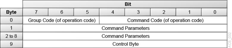
The structure for all command descriptor blocks is:
-
The first byte contains a Group code that provides 8 groups of commands and the Command Code that provides 32 command codes for each group.
-
The second byte in all command descriptor blocks starts the command parameters.
-
Any additional bytes contain command parameters.
-
The last byte in all command descriptor blocks contains the control byte.
6-Byte Command Descriptor Block
Figure 3-1 6-Byte Command Descriptor Block

Description of ''Figure 3-1 6-Byte Command Descriptor Block''
10-Byte Command Descriptor Block
Figure 3-2 10-Byte Command Descriptor Block
Description of ''Figure 3-2 10-Byte Command Descriptor Block''
12-Byte Command Descriptor Block
Figure 3-3 12-Byte Command Descriptor Block

Description of ''Figure 3-3 12-Byte Command Descriptor Block''
Control Byte
The control byte is the last byte of every command descriptor block.
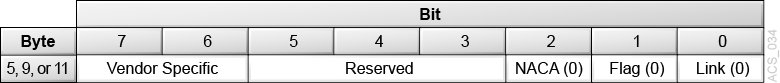
- Vendor Specific
-
Provides additional information about the device or for a command.
- NACA
-
The normal auto contingent allegiance bit controls the rules for handling an auto contingent condition caused by a command. This bit is set to 0 to indicate that if a contingent allegiance condition occurs, the command will return a check condition.
- Flag (not supported)
-
This bit causes an interrupt in the initiator allowing a device to respond with intermediate status. This bit is not supported and should be 0.
- Link (not supported)
-
Allows devices that support command linking to continue the I/O process. This bit is not supported and should be 0.
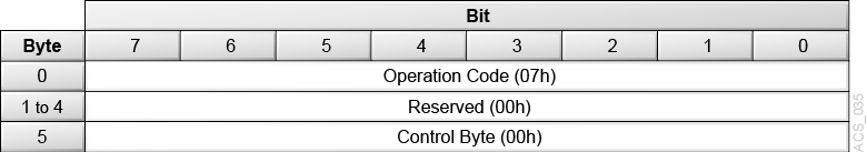
Initialize Element Status (07h)
The host uses the Initialize Element Status command (07h) to request an inventory of the cartridge tapes held in the library. The library accepts this command for compatibility, but does not perform any action. The command descriptor block is validated even though the command is not used. An initiator can obtain inventory information for the library by using the Read Element Status command.
Figure 3-5 Descriptor Block - Initialize Element Status (07h)
Description of ''Figure 3-5 Descriptor Block - Initialize Element Status (07h)''
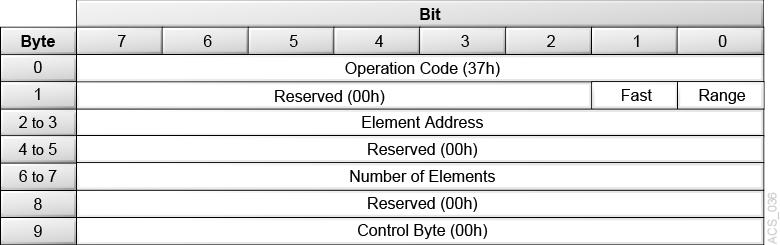
Initialize Element Status with Range (37h)
The Initialize Element Status With Range command (37h) is a request from the host to perform an inventory of a portion of the cartridge tapes within the library. The library accepts this command for compatibility, but does not perform any action.
The library performs an audit of and maintains the inventory upon power up. The library also performs an audit after some one has opened and closed the front door.
The command descriptor block is validated even though the command is not used. No checks are made of ignored fields (see below).
An initiator can obtain inventory information for the library by using the Read Element Status command.
Figure 3-6 Descriptor Block - Initialize Element Status with Range (37h)
Description of ''Figure 3-6 Descriptor Block - Initialize Element Status with Range (37h)''
- Fast
-
Ignore this field.
- Range
-
Ignore this field.
- Element Address
-
Ignore this field.
- Number of Elements
-
Ignore this field.
Inquiry Command (12h)
The Inquiry command (12h) requests that the library send to the initiator information regarding the library's parameters.
Note:
The Inquiry command returns check condition status only when the requested data cannot be returned. This command will not clear any pending unit attention conditions.Figure 3-7 Descriptor Block - Inquiry Command (12h)
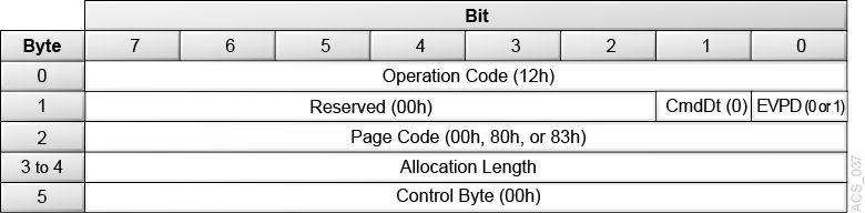
Description of ''Figure 3-7 Descriptor Block - Inquiry Command (12h)''
- CmdDt
-
The library returns a value of 0, indicating command support data is not supported.
- EVPD
-
The enable vital product data bit indicates the type of inquiry data the initiator is requesting. Supported values are:
-
0 = Request for normal inquiry data
-
1 = Request for vital support product data page
-
- Page Code
-
If the EVPD value is 0, this field must be 00h.
If the EVPD value is 1, this field must be:
-
00h = Supported vital product pages
-
80h = Unit serial number page
-
83h = Device identification page (Fibre only)
-
- Allocation Length
-
The allocation length field specifies the number of bytes the initiator has allocated for data returned from the Inquiry command.
A value of 0 indicates that no inquiry data is to be transferred. This condition is not considered an error.
The library terminates the Data In phase when it has transferred either the number of bytes specified by the Allocation Length field or all of the available inquiry data, whichever is less.
The data length for the normal inquiry data the library returns is 24h (36d) bytes. The data length for page 0 is 07h (7d). The data length for the unit serial number page (80h) is 0fh (15d) bytes. The data length for the device identification page (83h) is 18h (24d).
Normal Inquiry Data Definition
For the Inquiry command, the library returns 24h (36d) bytes of data in the format shown below.
Error Conditions: The library returns Check Condition status for the Inquiry command only when a severe error occurs. To recover from a Check Condition status report on the Inquiry command, verify that the Inquiry CDB is OK, and retry the Inquiry command.
Figure 3-8 Descriptor Block - Normal Inquiry Data Definition
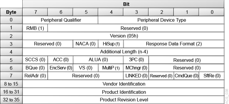
Description of ''Figure 3-8 Descriptor Block - Normal Inquiry Data Definition''
- Peripheral Qualifier
-
The library returns a value of 000b, which indicates that the library is a single logical unit number (LUN). If a logical library is not currently mapped to the lun, this field is set to 011b.
- Peripheral Device Type
-
The library returns a value of 8h, which indicates that the library is a medium changer device. If a logical library is not currently mapped to the lun, this field is set to 1fh.
- RMB
-
Removable Medium; a value of 1 indicates the medium is removable.
- Device-Type Modifier
-
A value of 0 indicates there are no modifiers for the library.
- Version
-
The library returns a value of 5h, which indicates compliance to SCSI-3.
- NormACA
-
The Normal Auto Contingent Allegiance (NACA) bit controls the rules for handling an auto contingent condition caused by a command.
The library returns a value of 0, indicating it does not support setting the NACA bit to one.
- HiSup
-
The library returns a value of 1, indicating it uses the hierarchical addressing model to assign LUNs to logical units.
- Response Data Format
-
A value of 2 indicates the data found is in accordance with the SCSI-3 specification.
- Additional Length
-
A value of 1fh indicates there are 24h (36) bytes of Inquiry data available to the initiator.
- SCCS
-
The library returns a value of 0, indicating the library does not contain an embedded storage array controller component.
- ACC
-
The library returns a value of 0, indicating it does not contain an access control coordinator that may be addressed through this logical unit.
- ALUA
-
The library returns a value of 0 for the asymmetrical logical unit access field, indicating asymmetric logical unit access is not supported.
- 3PC
-
The library returns a value of 0, indicating third-party commands are not supported.
- BQUE
-
The library returns a value of 0, indicating basic queuing is not supported.
- VS
-
Vendor Specific bit is set to 0, indicating there is no vendor-specific information with this command.
- MultiP
-
The library returns a value of 0, indicating multi-port attachments are not supported.
- MChngr
-
The library is not embedded in or attached to a medium transport element and returns a value of 0.
- RelAdr
-
The library returns a value of 0 for the relative addressing bit, indicating relative addressing is not supported.
- LINKED
-
The library returns a value of 0 for the LINKED command bit, indicating linked commands are not supported.
- CmdQue
-
The library returns a value of 0, indicating Command Queing is not supported.
- SftRe
-
The library returns a value of 0, indicating Soft Reset is not supported.
- Vendor Identification
-
Contains the ASCII character sequence ”SUN” followed by blanks. If the specified logical unit is not supported, this field contains all blanks.
- Product Identification
-
This field contains the ASCII character sequence ”ACSLS-SCSI” followed by blanks.
- Product Revision Level
-
For ACSLS, the initial product revision level is 1000.
Supported Pages Definition
The library returns 7d bytes of supported page data in the format shown below.
Figure 3-9 Descriptor Block - Supported Pages Definition
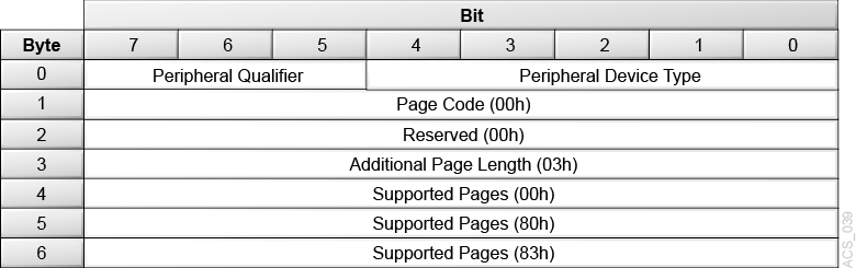
Description of ''Figure 3-9 Descriptor Block - Supported Pages Definition''
- Peripheral Qualifier
-
The library returns a value of 000b, which indicates that the library is a single logical unit number (LUN). If a logical library is not currently mapped to the LUN, this field is set to 011b.
- Peripheral Device Type
-
The library returns a value of 8h, which indicates that the library is a medium changer device. If a logical library is not currently mapped to the LUN, this field is set to 1fh.
- Page Code
-
Identifies the page as the supported pages (00h).
- Page Length
-
Indicates that three vital pages are supported (03h).
- Supported Page
-
The first supported page value is set to:
-
00h = Indicates the first vital page is page 0 (current page)
-
80h = Indicates the second vital page ("Unit Serial Number Page Definition")
-
83h = Indicates the third vital page ("Device Identification Page (Fibre Only)")
-
Unit Serial Number Page Definition
Figure 3-10 Descriptor Block - Unit Serial Number Page Definition
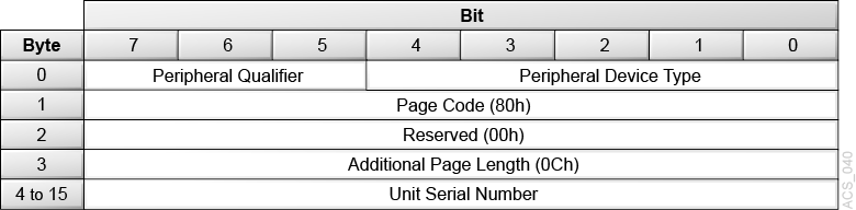
Description of ''Figure 3-10 Descriptor Block - Unit Serial Number Page Definition''
- Peripheral Qualifier
-
The library returns a value of 000b, which indicates that the library is a single logical unit number (LUN). If a logical library is not currently mapped to the lun, this field is set to 011b.
- Peripheral Device Type
-
The library returns a value of 8h, which indicates that the library is a medium changer device. If a logical library is not currently mapped to the lun, this field is set to 1fh.
- Page Code
-
This field is set to 80h, identifying the page as the unit serial number page.
- Additional Page Length
-
This field is set to 0Ch, the number of bytes in the product serial number.
- Unit Serial Number
-
Serial numbers for logical libraries consist of 12 ASCII numeric (0-9) characters that uniquely identify the library. The format is SSSSSSSSNNN where:
-
SSSSSSSS is the unique software serial number of the system.
-
NNNN is the ID of the logical library partition within the system (0-9999).
-
Device Identification Page (Fibre Only)
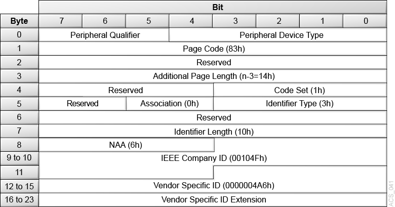
The library returns 24 bytes of device identification page data (page 83h) in the format shown below.
Figure 3-11 Descriptor Block - Device Identification Page (Fibre Only)
Description of ''Figure 3-11 Descriptor Block - Device Identification Page (Fibre Only)''
VPD page 83h returns a NAA type 6 IEEE Registered Extended identifier to uniquely identify the logical library.
- Code Set
-
1h = Identifier field contains binary values
- Association
-
0h = Identifier field is associated with the addressed logical unit
- Identifier Type
-
3h = Identifier field contains an NAA type identifier that is compatible with a Name_Identifier defined in FC-FS
- Identifier Length
-
10h = NAA type 6h identifier, IEEE Registered Extended, has a fixed length of 16 bytes
- IEEE Company ID
-
This field contains the 24 bit canonical form Object Unique Identifier (OUI) for StorageTek assigned by the IEEE, i.e. 00104Fh.
- Vendor Specific ID
-
The VSID encoding is 0000004A6h, which is the hexadecimal representation of the company unique product code within StorageTek for StorageTek ACSLS 8.x, i.e. 1190d.
- Vendor Specific ID Extension
-
This field contains a hexadecimal encoding of the serial number. Each character of the serial number is represented in a 4 bit nibble. For example, a library with serial number ”000012400002” the VSID Extension encoding would be 0000000012400002h.
Log Sense Command (4Dh) — Not Supported
This command is not supported.
Mode Select 6-byte (15h) and Mode Select 10-byte (55h) — Not Supported
These commands are not supported.
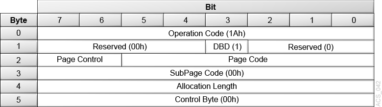
Mode Sense 6 (1Ah)
The Mode Sense 6 command (1A) enables the library to report its operating mode parameters to the initiator. The initiator can request one page or all pages of the mode parameters.
The Mode Sense (6) command only supports the Element Address Assignment (1Dh) and Device Capabilities (1Fh) pages. A library can be dynamically changed by the administrator using the GUI. Such changes include:
-
increasing or decreasing the number of storage elements
-
increasing or decreasing the number of import / export elements
-
adding or removing drives
Whenever the administrator makes any of these changes, the system presents a Unit Attention to the client application with the following sense information:
-
Sense Key 6h (Unit Attention) ASC / ASCQ 2Ah / 01h (Mode Parameters Changed)
Upon receipt of this Unit Attention, the client application should re-configure the library by using information returned by the Mode Sense command.
Figure 3-12 Descriptor Block - Mode Sense 6 (1Ah)
Description of ''Figure 3-12 Descriptor Block - Mode Sense 6 (1Ah)''
- DBD (Disable Block Descriptors)
-
Set to 1 to indicate that block descriptor should not be returned.
- Page Control
-
Defines the type of parameters to be returned for the Mode Sense command, values include:
-
0h (00b) = Current Values: The library returns the current parameter values. Since Mode Select is not supported, the current values will always be equal to the default values.
-
1h (01b) = Changeable Values: Not supported. The command terminates with Check Condition status and sense key of Illegal Request (5h) and ASC set to Invalid Field in CDB (24h).
-
2h (10b) = Default Values: The library returns the default values. Since Mode Select is not supported, the default values will always be equal to the current values.
-
3h (11b) = Saved Values: The library returns the saved values. Not supported. The command terminates with Check Condition status and sense key of Illegal Request (5h) and ASC set to Invalid Saving Parameters Not Supported (39h).
-
- Page Code
-
Specifies which pages the library returns, including:
-
1Dh = Element Address Assignment page
-
1Fh = Device Capabilities page
-
3Fh = All pages (in the above order)
-
- SubPage Code
-
Not supported.
- Allocation Length
-
Specifies the length of the parameter list the library returns. The maximum length is 2Ch (44d) bytes.The length varies based on the Page Code selected:
-
4 bytes for the parameter list header (always present)
-
20 additional bytes for the Element Address Assignment page
-
20 additional bytes for the Device Capabilities page
The library transfers the number of bytes specified by the Allocation Length or the available Mode Sense data, whichever is less.
-
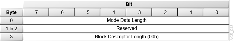
Mode Sense Parameter Header
Figure 3-13 Descriptor Block - Mode Sense Parameter Header
Description of ''Figure 3-13 Descriptor Block - Mode Sense Parameter Header''
- Mode Data Length
-
The bytes of parameter information available regardless of the allocation length. This value excludes the Mode Data Length byte, but includes three additional bytes (for Mode Sense 6-byte) or six additional bytes (for Mode Sense 10-byte) and the length of any mode pages that follow.
- Block Descriptor Length
-
00h = the library does not support block descriptors.
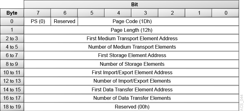
Element Address Assignment Page
Figure 3-14 Descriptor Block - Element Address Assignment Page
Description of ''Figure 3-14 Descriptor Block - Element Address Assignment Page''
- PS (Parameters Savable)
-
Specifies that the library cannot save this page to non-volatile memory and returns a value of 0.
- Page Code
-
Identifies the Element Address Assignment mode page and returns a value of 1Dh.
- Parameter Length
-
Indicates the amount of element address data following this byte and returns a value of 12h.
- First Medium Transport Element Address
-
Identifies the address of the robot and returns a value of 0h.
- Number of Medium Transport Elements
-
Identifies the number of hands within the library and returns a value of 0001h.
- First Storage Element Address
-
Identifies the starting address of the cartridge tape storage cells. The default starting address is 3E8h (100d).
- Number of Storage Elements
-
The number of data cartridge cells in the library or partition. The total number of cartridge tape storage cells depends on how the library is configured.
- First Import/Export Element Address
-
Identifies the address of the first Import/Export element. The default starting address is 000Ah (10d).
- Number of Import/Export Elements
-
Identifies the total number of import/export cells.
- First Data Transfer Element Address
-
Identifies the address of the first tape transport installed in the library. The default address is 1F4h (500d).
- Number of Data Transfer Elements
-
Identifies the number of tape drives in the library, and the library returns the configured count.
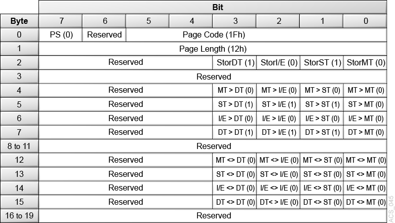
Device Capabilities Page
-
DT — Data Transfer Element (drive)
-
I/E — Import/Export Element (CAP cells)
-
ST — Storage Element (cartridge storage cell)
-
MT — Medium transport (robot hand)
Figure 3-15 Descriptor Block - Device Capabilities Page
Description of ''Figure 3-15 Descriptor Block - Device Capabilities Page''
- PS (Parameters Savable)
-
The library returns 0.
- Page Code
-
1Fh = The Device Capabilities mode page.
- Page Length
-
12h = 18 bytes of device capabilities data to follow.
- StorDT
-
1 = A tape drive can function as element storage.
- StorI/E
-
1 = A CAP cell can function as element storage.
- StorST
-
1 = A cartridge cell can function as element storage.
- StorMT
-
0 = The robot hand cannot function as element storage. You cannot use the robot as the source or destination of a move.
- MT > DT, MT > I/E, MT > ST, MT > MT, ST > MT, I/E > MT, DT > MT
-
0 = The robot hand (MT) cannot be the source or destination of a move.
- ST > DT, ST > I/E, ST > ST, I/E > DT, I/E > I/E, I/E > ST, DT > DT, DT > I/E, DT > ST
-
1 = Tape drives (DT), CAP cells (I/E), and cartridge cells (ST) are valid sources or destinations for a move.
- All <> Parameters
-
0 = The library does not support the exchange medium command.
Mode Sense 10-byte (5Ah) — Not Supported
This command is not supported.
Move Medium (A5h)
The Move Medium command (A5h) moves a cartridge tape from one specific element location to another specific element location. The Mode Sense command provides a matrix with the valid source and destination element combinations for the Move Medium command.
Medium movement occurs only for moves which involve a tape drive. All other move types are logical and do not cause real robotic activity.
Note:
Moves to import/export elements cause the medium to be immediately (logically) removed from the library. This means that import / export cells cannot be used as a place to store a volume. A Read Element Status command for an import/export element will always return a response of "empty". Also the command will fail with SenseKey Illegal Request (5h) and ACS/ASCQ Invalid Element (21/01h) if the source element address is an import/export element.The ACSLS Fast Load setting controls how completion of the move command is reported when the destination element is a tape drive.
With Fast Load enabled, a success status is returned once the operation has been validated and accepted by ACSLS, but before cartridge movement begins. If some error should occur during movement, ACSLS does not report that information. The client is responsible for identifying when the volume has been loaded and is usable, and for timing out the request in the case of any error.
With Fast Load disabled (the default setting), success status is not returned until the physical library has reported that the movement is complete. However, if an error should occur during movement, ACSLS reports that information to the client.
Please note that physical libraries may provide their own Fast Load option, which can affect the time required before ACSLS would return a success status (but only when ACSLS Fast Load is disabled). When ACSLS Fast Load is enabled, the library setting would have no effect on client notification.
Figure 3-16 Descriptor Block - Move Medium (A5h)
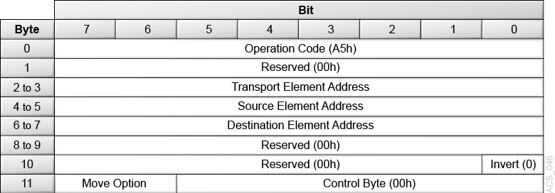
Description of ''Figure 3-16 Descriptor Block - Move Medium (A5h)''
- Transport Element Address
-
This field defines the robot element to use and should contain the element address 00h. A value of 00h indicates use of the default hand. If any other value is entered it will be ignored.
- Source Element Address
-
This field is the element address from which the cartridge tape is to be removed. This may be a storage cell or a tape drive.
- Destination Element Address
-
This field is the element address where the cartridge tape is to be placed. This may be a storage cell, a CAP cell, or a tape drive.
- Invert
-
The library does not support this function and requires a value of 0.
- Move Option
-
These two bits define optional operations associated with the Move Medium command.
-
00 = The library performs a normal move medium operation
-
10 = The library performs a mount operation with write protect enabled. That is, the user can read the data on the cartridge but cannot write to the cartridge.
This option is valid only when the destination element address is a data transfer element. If the destination data transfer element (tape drive) does not support this feature or fails to acknowledge the write-protected mount option, the mount fails. In either case, the library returns the Hardware Error sense key (04) with an ASC of 40 and an ASCQ of 02 (Drive Error).
-
11 = The data transfer element specified in the source element field performs a rewind, followed by a unload operation and then the move medium operation.
This option is valid only when the source element address is a data transfer element. Use this option with care because it might interfere with operations being performed on the data path of the data transfer element.
-
Persistent Reserve In (5Eh) — Not Supported
This command is not supported.
Persistent Reserve Out (5Fh) — Not Supported
This command is not supported.
Position to Element (2Bh)
The Position to Element command (2Bh) moves the virtual hand to the specified element. For the library, the command is supported but does not perform any action.
Figure 3-17 Descriptor Block - Position to Element (2Bh)
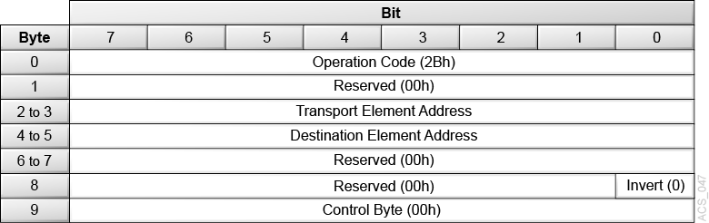
Description of ''Figure 3-17 Descriptor Block - Position to Element (2Bh)''
- Transport Element Address
-
This field defines the hand element to use and should contain the element address of the hand or 00h (0d). A value of 00h (0d) indicates use of the default hand.
- Destination Element Address
-
This field defines the address of the element where the hand is to be positioned.
- Invert
-
The library does not support this function and requires a value of 0.
Prevent/Allow Medium Removal (1Eh)
The Prevent/Allow Medium Removal command (1Eh) requests that the library enable or disable operator panel access to the cartridge access port (CAP). Since a logical library does not contain a physical CAP, this command is supported for compatibility but does not perform any action.
Figure 3-18 Descriptor Block - Prevent/Allow Medium Removal (1Eh)
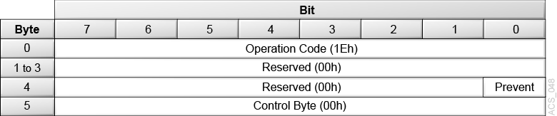
Description of ''Figure 3-18 Descriptor Block - Prevent/Allow Medium Removal (1Eh)''
- Prevent Bit
-
0 = The library allows operator panel access to unlock and open the indicated CAP.
1 = The library prevents access to the indicated CAP.
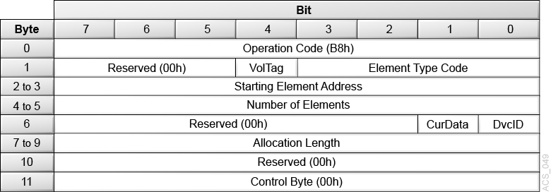
Read Element Status (B8h)
The Read Element Status command (B8h) requests that the library return the status of the elements in the library.
Figure 3-19 Descriptor Block - Read Element Status (B8h)
Description of ''Figure 3-19 Descriptor Block - Read Element Status (B8h)''
- Vol Tag
-
0 = Volume Tag information is not reported
1 = Volume Tag information is reported
Volume Tag information can be returned in more than one format. All formats are left justified and padded with ASCII blanks through byte 32, bytes 33-36 are zero. The library does not support sequence numbers. The format to be used is configured using the GUI. Configurable formats include:
-
6-character — format
vvvvvv, where:
vvvvvvis the ascii volser -
8-character Suffixed — format
vvvvvvdtorvvvvvvbt, where:
vvvvvvis the ascii volser
dis the media domain
bis the an ascii blank
tis the media type -
8-character Prefixed — format
dtvvvvvv orbtvvvvvv, where:
dis the media domain
bis the an ascii blank
tis the media type
vvvvvvis the ascii volser -
Open Format — the complete bar code as reported by the backing physical library.
-
- Element Type Code
-
0h = All Element Types reported. The element types are reported in ascending element address order, beginning with the first element greater than or equal to the Starting Element Address.
1h = Medium Transport Element (hand)
2h = Storage Element (cartridge tape storage cells)
3h = Import/Export Element (CAP cells and PTP cells)
4h = Data Transfer Element (tape drive)
- Starting Element Address
-
This field specifies the minimum element address to report. Only elements with an element address greater than or equal to the Starting Element Address are reported.
Element descriptor blocks are not generated for undefined element addresses.
The Starting Element Address must be a valid address for the library but does not have to be an address of the type requested in the Element Type Code.
- Number of Elements
-
This field represents the maximum number of element descriptors to be transferred. This is an actual number of element descriptors to be transferred, not an element address range.
- Cur Data
-
0 = Library operations are normal, and library mechanics may become active if needed to gather element static data.
1 = The library is responding with data only; no mechanical operations are active. The CurData bit is effectively ignored by the library. The library will perform or not perform mechanical operations to obtain proper information at its discretion independently of the setting of this bit.
- DvcID
-
0 = The library will not return device identification information.
1 = The library will return device identification information only for data transfer elements.
- Allocation Length
-
This field specifies the length in bytes of the space allocated by the initiator for the transfer of element descriptors. Only complete element descriptors are transferred. Element descriptors are transferred until one of the following conditions is met:
-
All available element descriptors of the type specified in the Element Type Code have been transferred.
-
The number of element descriptors specified in the Number of Elements field have been transferred.
-
There is less allocation length space available than required for the next complete element descriptor or header to be transferred.
-
- Read Element Status Data
-
The library returns data for a Read Element Status command with an eight-byte Element Status Data header, followed by one to four element pages, one page per element type.
A page consists of an eight-byte Element Status Page header, followed by one or more Element Descriptors. The format of the descriptor is based on the element type reported in this page. Each element type receives a separate Element Descriptor format.
Data can be truncated based on the length specified in the allocation field.
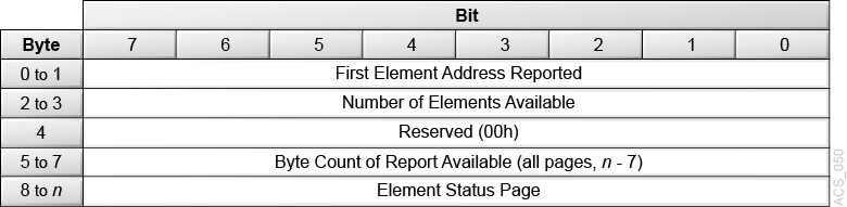
Element Status Data Header Definition
The library sends this header once for each Read Element Status command.
Figure 3-20 Descriptor Block - Element Status Data Header Definition
Description of ''Figure 3-20 Descriptor Block - Element Status Data Header Definition''
- First Element Address Reported
-
This field indicates the lowest element address found of the type specified in the Element Type Codes and greater than or equal to the Starting Element Address.
- Number of Elements Available
-
This field indicates the number of elements found of the type specified in the Element Type Codes and greater than or equal to the Starting Element Address. This number is adjusted to be less than or equal to the count specified in the Number of Elements field in the Read Element Status command.
- Byte Count of Report Available
-
This field indicates the number of bytes of element status data available for all elements meeting the requirements of the Read Element Status command. This count does not include the Element Status Data header bytes. This value is not adjusted to match the allocation length from the command.
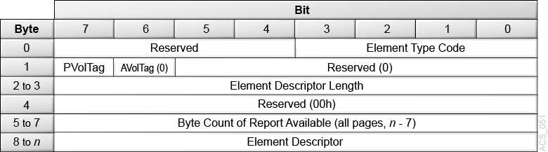
Element Status Page Header
The library sends this header once for each type of element descriptors.
Figure 3-21 Descriptor Block - Element Status Page Header
Description of ''Figure 3-21 Descriptor Block - Element Status Page Header''
- Element Type Code
-
See "Element Type Code" .
- PVolTag
-
0 = Volume Tag information has not been requested. The data is omitted from the element descriptors.
1 = Volume Tag information has been requested to be reported and is present.
- AVolTag
-
The library does not support alternative volume tags (AVolTag) and returns a value of 0.
- Element Descriptor Length
-
This field indicates the total number of bytes contained in a single element descriptor.
- Byte Count of Descriptor Data Available
-
This field indicates the total number of bytes of element descriptor data available for the elements of this element type that meet the requirements of the Read Element Status command. This count does not include the Element Status Page header bytes. This value is not adjusted to match the allocation length.
- Element Descriptors
-
See below.
Element Descriptors
The following sections contain the field definitions for the four types of library elements, which are:
-
Medium Transport Element (the hand)
-
Storage Element (cartridge tape storage cells)
-
Import/Export Element (CAP cells and PTP cells)
-
Data Transfer Element (tape drives)
Each element descriptor includes the element address and status flags. Each element descriptor might also contain sense key information as well as other information, depending on the element type.
The element descriptors for the four types of elements are similar, with the exception of a few fields. Note the differences in Bytes 02, 06, and 07 for the four element descriptors.
The library does not support alternate volume tags. This information is not included in any of the element descriptors.
Medium Transport Element Descriptor
Medium transport elements are robotic components capable of physically moving cartridges. The Medium Transport Element Descriptor defines the robot characteristics.
Figure 3-22 Medium Transport Element Descriptor
Description of ''Figure 3-22 Medium Transport Element Descriptor''
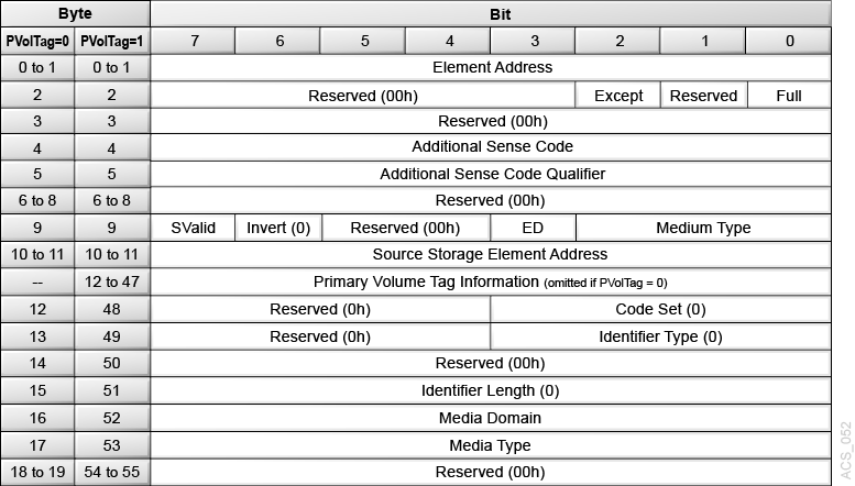
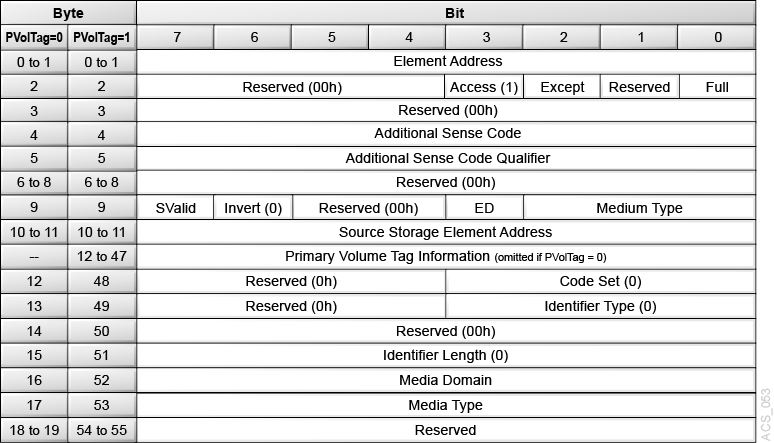
Storage Element Descriptor
Storage elements are the main cartridge tape storage cells of the library.The Storage Element Descriptor describes a storage cell.
Import/Export Element Descriptor
Import/Export elements are the CAP and/or Pass-thru cells of the library. The Import/Export Element Descriptor describes a CAP cell.
Figure 3-24 Import/Export Element Descriptor
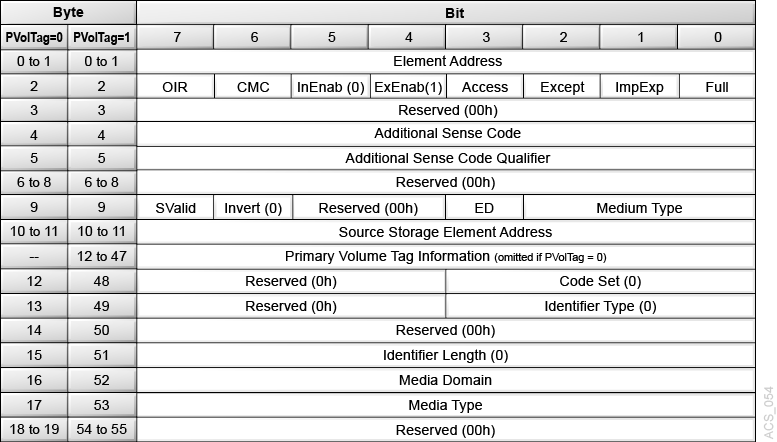
Description of ''Figure 3-24 Import/Export Element Descriptor''
Data Transfer Element Descriptor
Data transfer elements are the tape drives in the library. The Data Transfer Element Descriptor Definitions page describes a tape drive.
Figure 3-25 Data Transfer Element Descriptor (DvcID = 0)
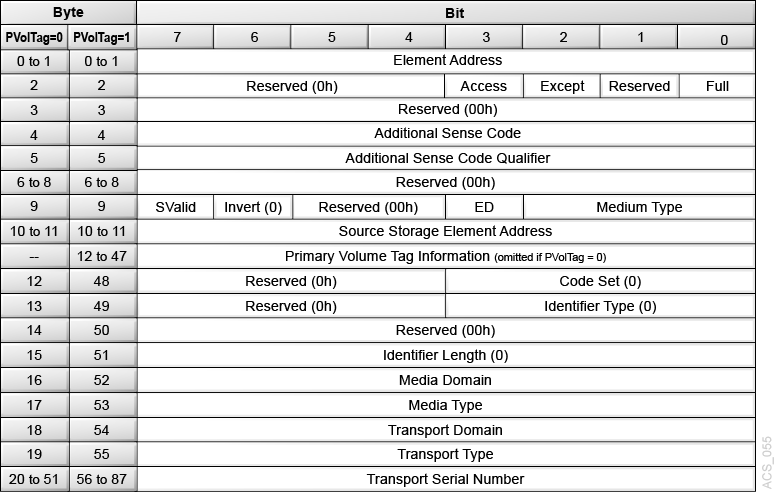
Description of ''Figure 3-25 Data Transfer Element Descriptor (DvcID = 0)''
Figure 3-26 Data Transfer Element Descriptor (DvcID = 1)
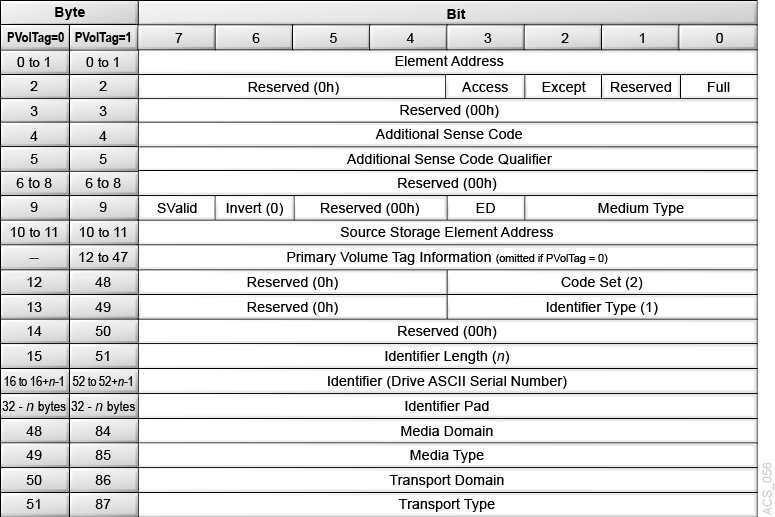
Description of ''Figure 3-26 Data Transfer Element Descriptor (DvcID = 1)''
Element Descriptor Definitions
- Element Address
-
The address of the element (robot hand, cartridge cell, CAP cell, drive, or empty drive slot).
- OIR
-
0 = No operator intervention required to make the CAP accessible
1 = Operator intervention required to make the CAP accessible
- CMC
-
0 = The import/export element is a CAP. The cartridge will not leave the library when prevented by the Prevent/Allow Medium Removal (1Eh) command.
- InEnab
-
1 = The CAP supports importing cartridges.
- ExEnab
-
1 = The CAP supports exporting cartridges.
- Access
-
0 = The robot cannot access the element. For Import/Export elements, this can occur when the CAP is open or a CAP magazine was removed. For Data transfer elements, this can occur when a cartridge is loaded in a drive.
1 = The robot can access the element
- Except
-
0 = The element is in a normal state
1 = The element is in an abnormal state. The Additional Sense Code (ASC) and the Additional Sense Code Qualifier (ASCQ) fields contain information regarding the abnormal state. Other fields in the descriptor might be invalid and should be ignored.
- ImpExp
-
0 = The robot placed the cartridge in the CAP for an export operation.
1 = An operator placed the cartridge in the CAP for an import operation.
- Full
-
0 = The element does not contain a cartridge
1 = The element contains a cartridge
- ASC (Additional Sense Code)
-
This field is valid only if the Except bit is set. In the case of an exception, it contains an ASC as defined for Request Sense data.
- ASCQ (Additional Sense Code Qualifier)
-
This field is valid only if the Except bit is set. In the case of an exception, it contains an ASCQ as defined for Request Sense data.
Condition ASC Value ASCQ Value CAP Open 3Ah 02h Empty Drive Slot (no drive installed) 3Bh 1Ah Drive Hardware Error 40h 02h - SValid
-
0 = The Source Element Address and Invert fields are not valid.
1 = The Source Element Address and Invert fields are valid.
- Invert (not supported)
-
0 = The library does not support multi-sided media.
- ED
-
0 = The element is enabled.
1 = The element is disabled (for example an open CAP, a drive hardware error, or empty drive slot).
- Medium Type
-
The type of medium currently present in the element as determined by the medium changer.
0h = Unspecified - the medium changer cannot determine the medium type.
1h = Data Medium
2h = Cleaning Medium
- Source Storage Element Address
-
This field is valid only if the SValid field is 1. This field provides the address of the last storage element this cartridge occupied. The element address value may or may not be the same as this element.
- Primary Volume Tag Information
-
When PVolTag is 1, the library returns volume tag information. When PVolTag is 0, the library omits volume tag information.
The Primary Volume Tag field contains the null-terminated ASCII barcode label on the tape cartridge. If the label on the cartridge tape is not readable or if the element is empty, the Primary Volume Tag field is filled with 36 bytes of zeros. The "Volume Label Format" controls the presentation of the volser in the Primary Volume Tag field. The library supports the following settings:
-
Full Label
-
No Type Checking
-
Prepend Last Two Characters
-
Trim Last Character
-
Trim Last Two Characters
-
Trim First Two Characters
-
Trim First Character
For more information, see the SL4000 GUI help.
-
- Code Set
-
0h = Reserved (not supported) for the Medium Transport Element, Storage Element, Import/Export Element, or Data Transfer Element (DvcID = 0) descriptors.
2h = The identifier contains ASCII graphic codes (code values 20h through 7Eh) for Data Transfer Element (DvcID = 1) descriptor.
- Identifier Type
-
The format and assignment authority for the identifier.
0h = The library returns vendor specific data.
- Identifier Length
-
The combined length of the Identifier and the Identifier Pad.
00h = The library returns 0 bytes of identifier data in the descriptors for Medium Transport Elements, Storage Elements, Import/Export Elements, or Data Transfer Elements (DvcID = 0).
20h = The library returns 32 bytes of identifier data for the Data Transfer Element (DvcID = 1).
- Identifier (for Data Transfer Element DvcID = 1 Only)
-
The ASCII Serial Number for the tape drive associated with this data transfer element.
- Identifier Pad (for Data Transfer Element DvcID = 1 Only)
-
Contains ASCII blanks. The number of blanks depends on the length of the Identifier field. The combined length of the Identifier field and the Identifier Pad is 32 bytes.
- Media Domain
-
43h ('C') = The element contains a cleaning cartridge.
4Ch ('L') = The element contains an LTO cartridge.
54h ('T') = The element contains a T10000 cartridge.
FFh = The media domain cannot be determined or the element is empty.
- Media Type
-
FFh = The media type cannot be determined or the element is empty.
If the Media Domain is 43h (C):
-
C = The element contains a T10000 Version 2 cleaning cartridge
-
L = The element contains a T10000 Universal cleaning cartridge.
-
T = The element contains a T10000 Version 1 cleaning cartridge.
-
U = The element contains a Universal LTO cleaning cartridge.
If the Media Domain is 4Ch (L):
-
3 = The element contains a 400 GB Generation 3 LTO cartridge.
-
4 = The element contains an 800 GB Generation 4 LTO cartridge.
-
5 = The element contains a 1.5 TB Generation 5 LTO cartridge.
-
6 = The element contains a 2.5 TB Generation 6 LTO cartridge.
-
7 = The element contains a 6 TB Generation 7 LTO cartridge.
-
8 = The element contains a 12 TB Generation 8 LTO cartridge.
-
T = The element contains a 400 GB Generation 3 LTO WORM cartridge.
-
U = The element contains an 800 GB Generation 4 LTO WORM cartridge.
-
V = The element contains a 1.5 TB Generation 5 LTO WORM cartridge.
-
W = The element contains a 2.5 TB Generation 6 LTO WORM cartridge.
-
X = The element contains a 6 TB Generation 7 LTO WORM cartridge.
-
Y = The element contains a 12 TB Generation 8 LTO WORM cartridge.
If the Media Domain is 54h (T):
-
1 = The element contains a T10000 Version 1 cartridge.
-
2 = The element contains a T10000 Version 2 cartridge.
-
S = The element contains a T10000 Version 1 Sport cartridge.
-
T = The element contains a T10000 Version 2 Sport cartridge.
-
- Transport Domain
-
4Ch (L) = The drive supports LTO cartridges.
54h (T) = The drive supports T10000 cartridges.
FFh = The element domain cannot be determined.
- Transport Type
-
FFh = The type cannot be determined.
If the Transport Domain is 4Ch (L):
-
3Bh = HP Generation 5 LTO drive
-
3Ch = IBM Generation 5 LTO drive
-
3Dh = HP Generation 6 LTO drive.
-
3Eh = IBM Generation 6 LTO drive.
-
2Dh = IBM Generation 7 LTO drive.
-
2Eh = IBM Generation 8 LTO drive.
If the Transport Domain is 54h (T):
-
0Dh = StorageTek T10000A drive.
-
0Eh = StorageTek T10000A drive in 3590 emulation mode.
-
18h = StorageTek T10000A Encrypting drive.
-
19h = StorageTek T10000A Encrypting drive in 3590 emulation mode.
-
1Ah = StorageTek T10000B drive.
-
1Bh = StorageTek T10000B drive in 3590 emulation mode.
-
1Ch = StorageTek T10000B Encrypting drive.
-
1Dh = StorageTek T10000B Encrypting drive in 3590 emulation mode.
-
22h = StorageTek T10000C drive.
-
23h = StorageTek T10000C drive in 3590 emulation mode.
-
24h = StorageTek T10000C Encrypting drive.
-
25h = StorageTek T10000C Encrypting drive in 3590 emulation mode.
-
26h = StorageTek T10000D drive.
-
27h = StorageTek T10000D drive in 3590 emulation mode.
-
28h = StorageTek T10000D Encrypting drive.
-
29h = StorageTek T10000D Encrypting drive in 3590 emulation mode.
-
2Ah = StorageTek T10000D Fibre Channel over Ethernet.
-
2Bh = StorageTek T10000D Fibre Channel over Ethernet Encrypting drive.
-
- Transport Serial Number
-
The 32-byte ASCII serial number for the drive.
For drives with a serial number less than 32 bytes, the library left-justifies the value by returning ASCII blanks for the unused less-significant bytes. If the serial number is not available from a drive that should support an ASCII serial number, the library returns all ASCII blanks.
Release 6-byte (17h) and Release 10-byte (57h) — Not Supported
These commands are not supported.
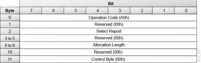
Report LUNs (A0h)
The Report LUNs command (A0) returns to the initiator the known LUNs to which the initiator can send commands. Each LUN returned represents a logical library. Only LUN 0 is supported in the library.
Figure 3-27 Descriptor Block - Report LUNs (A0h)
Description of ''Figure 3-27 Descriptor Block - Report LUNs (A0h)''
- Allocation Length
-
This field specifies the number of bytes that the initiator has allocated for data to be returned from the Report LUNs command.
The Allocation must be at least 16 bytes. If it is less, a check condition is returned with the sense key set to illegal request and the additional sense data set to invalid field in the command descriptor block (CDB).
- Select Report
-
This field specifies the type of logical unit addresses that shall be reported.
00h = The LUN addresses reported shall be limited to the following addressing methods: LUN addressing method, Peripheral device addressing method, and flat space addressing method.
02h = All LUNS accessible to the initiator for this port are accessible
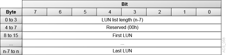
Report LUNs Data Definition
The target device returns the following data for the Report LUNs command.
Figure 3-28 Descriptor Block - Report LUNs Data Definition
Description of ''Figure 3-28 Descriptor Block - Report LUNs Data Definition''
- LUN list length
-
The target device returns a LUN list length of n-7. Each LUN returned represents a logical library. If no logical libraries have been mapped for the requesting initiator, LUN 0 is still returned.
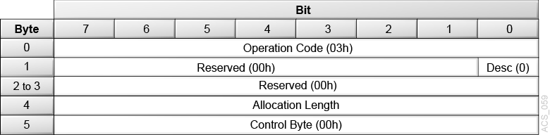
Request Sense (03h)
The Request Sense command (03) requests the library transfer sense data to the initiator.
Logical libraries use an FC-2 conforming transport that provides autosense. This means that sense data for a failed command is always returned with a Check Condition status in the command response and is never saved by the target. Therefore, Request Sense will always return Sense Data with a Sense Key set to No Sense and ASC/ASCQ fields set to 0.
However, all Sense Keys and associated ASC/ASCQ fields that can be returned by other commands are documented here.
Figure 3-29 Descriptor Block - Request Sense (03h)
Description of ''Figure 3-29 Descriptor Block - Request Sense (03h)''
- Desc
-
The Desc bit indicates which sense data format shall be returned.
The library returns a value of 0, indicating fixed format sense data is returned.
- Allocation Length
-
This field specifies the number of bytes that the initiator has allocated for returned sense data. The library provides a maximum of 14h (20d) bytes of sense data.
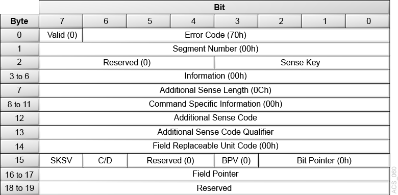
Request Sense Data Definitions
Figure 3-30 Descriptor Block - Request Sense Data Definitions
Description of ''Figure 3-30 Descriptor Block - Request Sense Data Definitions''
- Valid
-
0 = The library does not return data in the Information field.
- Error Code
-
70h = The library returns only current errors.
- Segment Number
-
00h = The library does not support segment numbers.
- Sense Key
-
Describes the error, along with ASC and ASCQ. See Additional Sense Codes and Qualifiers.
0h = No Sense, indicating a successful command.
2h = Not Ready
3h = Medium Error
4h = Hardware Error
5h = Illegal Request
6h = Unit Attention
Bh = Aborted Command
- Information
-
00h = The library does not support this field.
- Additional Sense Length
-
0Ch = Indicates there are 12d bytes of additional sense bytes to follow. This value is not truncated to reflect the actual transfer length.
- Command Specific Information
-
00h = The library does not support this field.
- Additional Sense Code (ASC)
-
Describes the error. See Additional Sense Codes and Qualifiers.
- Additional Sense Code Qualifier (ASCQ)
-
Describes the error. See Additional Sense Codes and Qualifiers.
- Field Replaceable Unit Code
-
00h = The library does not support this field.
- SKSV (Sense Key Specific Valid)
-
1 = The C/D and field pointer are valid
0 = Ignore the C/D and field pointer
- C/D (Command/Data)
-
0 = The check condition status resulted from illegal parameter in the parameter list.
1 = The check condition status resulted from illegal parameter in the CDB.
- BPV (Bit Pointer Valid)
-
0 = The library does not support this field.
- Bit Pointer
-
0h = The library does not support this field.
- Field Pointer
-
The number of the byte where the error occurred. When a multiple-byte field is in error, the Field Pointer contains the value of the most significant byte of the field, which is lowest byte number. Byte numbers start at 00.
Additional Sense Codes and Qualifiers
Not Ready Sense Key Code (2h)
The library generates a Not Ready error code if you send a command when the library is in a not ready state.
| Description | Sense Key | ASC | ASCQ |
|---|---|---|---|
| Not Ready, Maintenance Mode | 2h | 04h | 81h |
- Not Ready, Maintenance Mode
-
The library was placed in maintenance mode from the operator panel or user interface. The logical library is offline.
Hardware Error Sense Key Code (4h)
The library generates a Hardware Error if it detects a hardware or firmware error during command execution.
| Description | Sense Key | ASC | ASCQ |
|---|---|---|---|
| Hardware Error, Tape Drive | 4h | 40h | 02h |
| Hardware Error, Internal Target Failure | 4h | 44h | 00h |
- Hardware Error, Tape Drive
-
An operation to the drive failed. The problem could be the tape drive or the interface between the library and tape drive.
- Hardware Error, Internal Target Failure
-
The library generates a hardware error when an unexpected condition is detected by ACSLS software that controls the SCSI interface. This error is used for arbitrary limitations of the software.
Illegal Request Sense Key Code (5h)
Any illegal parameters in the CDB or parameter list for a particular command generates an Illegal Request sense key.
In some cases, additional information is available in Byte 15 of the sense data, which includes the sense-key-specific-value (SKSV) and command/data (C/D) fields. This information indicates the byte in the command descriptor block or the parameter list that is in error. If available, the SKSV bit in the sense data is set to 1.
| Description | Sense Key | ASC | ASCQ | SKSV |
|---|---|---|---|---|
| Invalid Command Operation Code | 5h | 20h | 00h | Yes |
| Invalid Element Address | 5h | 21h | 01h | No |
| Invalid Field in CDB | 5h | 24h | 00h | Yes |
| Logical Unit Not Supported | 5h | 25h | 00h | No |
| Incompatible Medium | 5h | 30h | 00h | No |
| Saving Parameters Not Supported | 5h | 39h | 00h | Yes |
| Medium Not Present, Drive Not Unloaded | 5h | 3Ah | 00h | No |
| Destination Element Full | 5h | 3Bh | 0Dh | No |
| Source Element Empty | 5h | 3Bh | 0Eh | No |
Unit Attention Sense Key Code (06h)
The library generates a Unit Attention sense key for all initiators if the library needs to inform the host of an asynchronous event.
| Description | Sense Key | ASC | ASCQ |
|---|---|---|---|
| Not Ready-to-Ready Transition | 06h | 28h | 00h |
| CAP Element Accessed | 06h | 28h | 01h |
| Mode Parameters Changed | 06h | 2Ah | 01h |
| Reservations Preempted | 06h | 2Ah | 03h |
| Reservations Released | 06h | 2Ah | 04h |
| Registrations Preempted | 06h | 2Ah | 05h |
| LUNs Data Has Changed | 06h | 3Fh | 0Eh |
- Not Ready to Ready Transition
-
The library transitioned to a Ready state from a Not Ready state. The library sends this unit attention to all initiators.
- CAP Element Accessed
-
The operator opened and closed the CAP. The library sends this unit attention to all initiators. You can issue a Read Element Status command to obtain an updated inventory (see Read Element Status (B8h).
- Mode Parameters Changed
-
The operator added or removed elements from a partition. Send a Read Element Status (B8h) command to obtain an updated inventory. Send a Mode Sense command with Element Address page code to request the current count of each element type.
- Persistent Reservations/Registrations Preempted or Released
-
A different initiator issued a Persistent Reservation Out command that cleared the registration for this initiator or cleared a reservation that affects this initiator.
- LUNs Data Has Changed
-
The LUN configuration for the initiator has changed. The library sends this unit attention when the operator adds or removes a LUN connection from a partition for the initiator.
Aborted Command Sense Key Code (0Bh)
The library generates an Aborted Command error code when a SCSI command is aborted.
| Description | Sense Key | ASC | ASCQ |
|---|---|---|---|
| Command Overlap | 0Bh | 4Eh | 00h |
- Command Overlap
-
The library detected another command from an initiator while one was already in process.
Request Volume Element Address (B5h) — Not Supported
This command is not supported.
Reserve 6-byte (16h) and Reserve 10-byte (56h) — Not Supported
This command is not supported.
Send Diagnostic (1Dh) — Not Supported
This command is not supported.
Send Volume Tag (B6h) — Not Supported
This command is not supported.
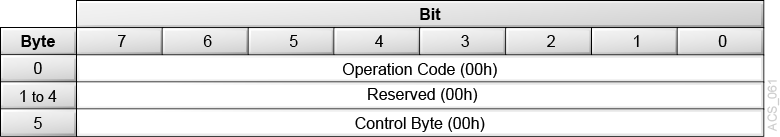
Test Unit Ready (00h)
The Test Unit Ready command (00h) allows the initiator to determine if the library is powered-on and ready to accept additional commands. This is not a request for a library self-test.
The Test Unit Ready command returns a Good status if the library is ready to accept additional commands. This command also returns a Check Condition if the library is not ready or if there are pending Unit Attentions.
Figure 3-31 Descriptor Block - Test Unit Ready (00h)
Description of ''Figure 3-31 Descriptor Block - Test Unit Ready (00h)''
Write Buffer (3Bh) — Not Supported
This command is not supported.