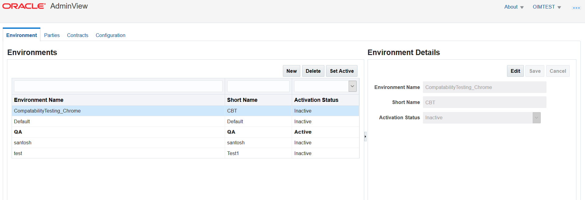
A successful log in to the OIDG portal places you on the home page. Click the ‘AdminView’ icon under Administration tab to access the AdminView application. A new tab starts in your browser where you can use this application.
Figure 3.1.1 - AdminView Home Page
The Environments, Parties, Contracts and Configuration tabs are available for selection in the top left area of the page.
These tabs allow you to switch between the tasks corresponding to your requirements.
AdminView Tabs
Application functionality is divided into four major areas on the following tabs:
Environments Tab
This tab allows you to configure multiple configuration domains. This allows you to use one deployment of AdminView to point to party services in different environments like SIT, UAT, QA, and Production without having to update all your endpoint details each time you want to switch between environments.
Parties Tab
This tab allows you to define the sender and receiver parties, select business services to integrate them on, and to define the party service endpoints details.
Contracts Tab
This tab allows you to create and manage business service integration contracts between sender and receiver parties. Contracts can be enabled and disabled without deleting integration configuration settings. User can also configure notification endpoints from this tab.
Configuration Tab
This tab allows you to configure properties and viewing partner configuration XML file.
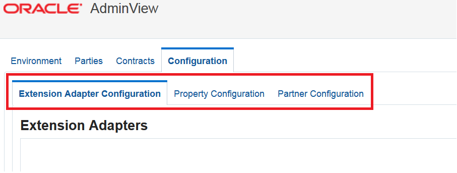
Configuration Tab
The Configuration tab allows you to configure extension adapters , configuring properties and viewing the ‘Partner Config XML’ file. This tab includes:
Extension Adapter Configuration – Allows to configure adapter
Property Configuration – Allows to configure properties
Partner Configuration – Provides access to Partner Config XML file
Figure 3.1.2 - Configuration Tab
Configuring Extension Adapters
The ‘Extension Adapter Configuration’ tab allows you to configure extension adapter to make them pluggable in AdminView. Extension adapter must be defined before creating an endpoint. Once you create an extension adapter, it will be available for selection under ‘Creating Endpoint’ section.
Creating an Adapter
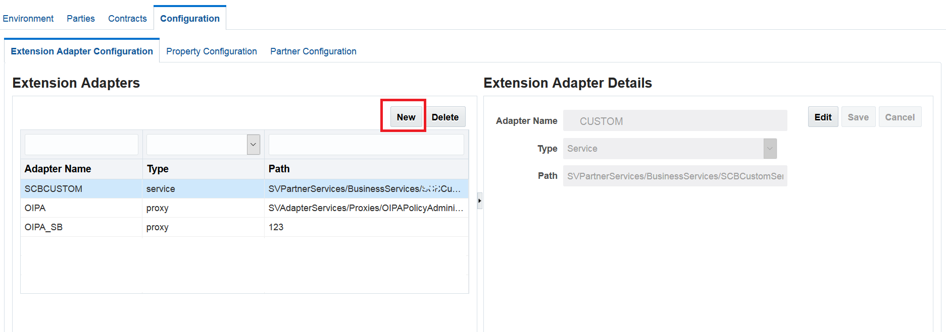
To create a new extension adapter, follow these steps:
Click ‘New’ under ‘Extension Adapter’ section. Figure 3.1.3 - Creating New Extension Adapter
Enter following details under ‘Extension Adapter Details’ section.
Adapter Name – Name of the adapter you wish to create. You may use spaces and underscore in your adapter name. Adapter name must be unique.
Type – Select the adapter type using the drop-down. If the adapter is accessed using a local proxy, as in the case of the built-in OIPA adapter, select the ‘Proxy’ Type. If the adapter is accessed over HTTP using a local business service component, as will be the case for custom adapters, select the ‘Service’ Type.
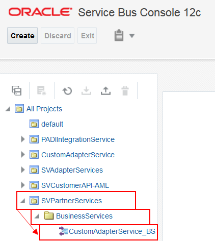
Path – Enter the path for selected adapter type. This is the project path where the adapter’s proxy or business service component is located in the Service Bus deployment.
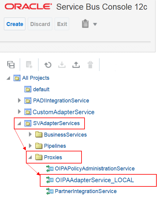
The path can be determined as presented in the following example:
Go to the Oracle Service Bus console.
Expand the deployed Service Virtualization components as shown in the screenshots.
Click ‘Save’ once you’ve entered the above details.
Editing an Adapter
To edit an existing adapter, follow these steps:
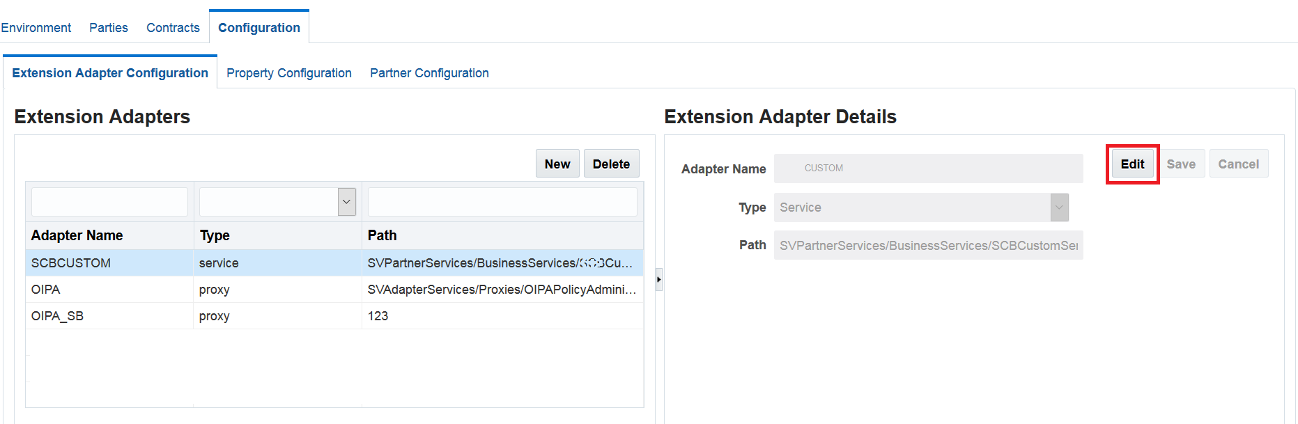
Select the row of the extension adapter you wish to edit. Under Extension Adapter Details, the ‘Edit’ button is activated. Figure 3.1.6 - Editing an Adapter
Click ‘Edit’ and make the changes.
Click ‘Save’ once you’ve completed editing.
Deleting an Adapter
To delete an adapter, follow these steps:
Select the row of the extension adapter you wish to delete.
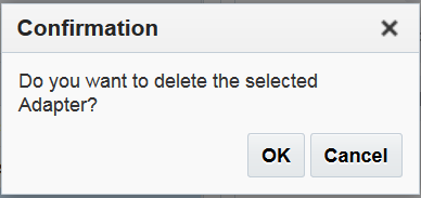
Click ‘Delete’. A pop up dialog appears for confirmation.
If the extension adapter is not linked to an endpoint, following dialog appears. Figure 3.1.7 - Confirmation Dialog
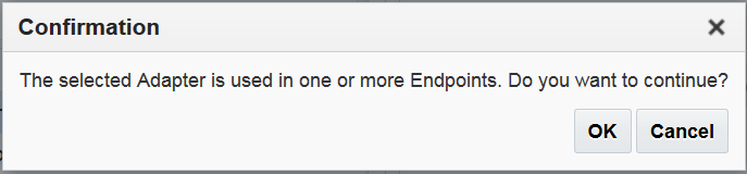
If the extension adapter is linked to an endpoint(s), following dialog appears. Figure 3.1.8 - Confirmation Dialog (If an endpoint is linked)Clicking ‘OK’ will make the adapter value null for respective endpoint(s).
Click ‘Ok’ to delete the extension adapter.
Configuring Properties
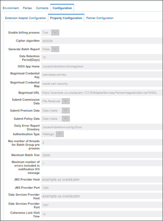
The ‘Property Configuration’ tab allows you to configure system properties that are required for the OIDG application and determine the authentication type. These properties must be configured before using OIDG. Clicking the ‘Property Configuration’ tab allows you to enter following details:
Figure 3.1.9 - Property Configuration Tab
Field
Description
Enable billing process
This property is used to enable/disable billing functionality
Cipher algorithm
The algorithm used to encrypt and decrypt the file
Generate Batch Report
Setting to true will generate XML report
Data Retention Period (Days)
The duration to clear data
OIDX App Home
Configurable where all processing files are generated and moved in to the request – error – backup
Beginload Credential Key
The credential key where users and passwords are defined to access Beginload web service
Beginload Credential Map
The credential map where key to store Beginload web service connection credentials are configured
Submit Commission Data
Select the mechanism to submit commission data
• Data Intake
• File Received
Submit Premium Data
Select the mechanism to submit premium data
• Data Intake
• File Received
Submit Policy Data
Select the mechanism to submit policy data
• Data Intake – An Oracle Insurance Policy Administration queue-based integration transport type
• File Received
Data Error Report Directory
The path where daily error reports are placed
Authentication Type
Two types of authentication:
• OIM
• Weblogic
See Overview section to know more about these.
Max number of threads for Batch Group pre process
Maximum number of threads to be used to process the batch Group concurrently. The default value is 10.
Increasing this value results better performance if the environment has sufficient resources to handle load.
Maximum Batch Size
Enter an integer. If you try to process larger batch than the configured size, the batch initiation is canceled.
Maximum number of errors included in notification WS message
Maximum number of errors to be included in the notification web service. If number of errors are more than defined errors, only defined errors will be included in the notification. Remaining errors are ignored .
JMS Provider Host
The host name or IP of the managed server to which OICSJMSServer is targeted Note:
For Vertical cluster node installation – Enter host name
For Horizontal cluster node installation – Enter Node1 host name and Node2 host name separated by comma
JMS Provider Port
The managed server port to which OICSJMSServer is targeted Note:
For Vertical cluster node installation – Enter Node1 SOA port and Node 2 SOA port separated by comma
For Horizontal cluster node installation – Enter Node1 SOA port and Node 2 SOA port separated by comma
Data Services Provider Host
Application server URL, hostname Note:
For Vertical cluster node installation – Enter host name
For Horizontal cluster node installation – Enter Node1 host name and Node2 host name separated by comma
Data Services Provider Port
Enter port number Note:
For Vertical cluster node installation – Enter Node1 AML port and Node 2 AML port separated by comma
For Horizontal cluster node installation – Enter Node1 AML port and Node 2 AML port separated by comma
Coherence Lock Wait Time
The duration OIDG waits for getting a cache object lock from coherence. If the duration exceeds the limit, the process is canceled and an error message is logged. The value is an integer in seconds. The recommended value is 10.
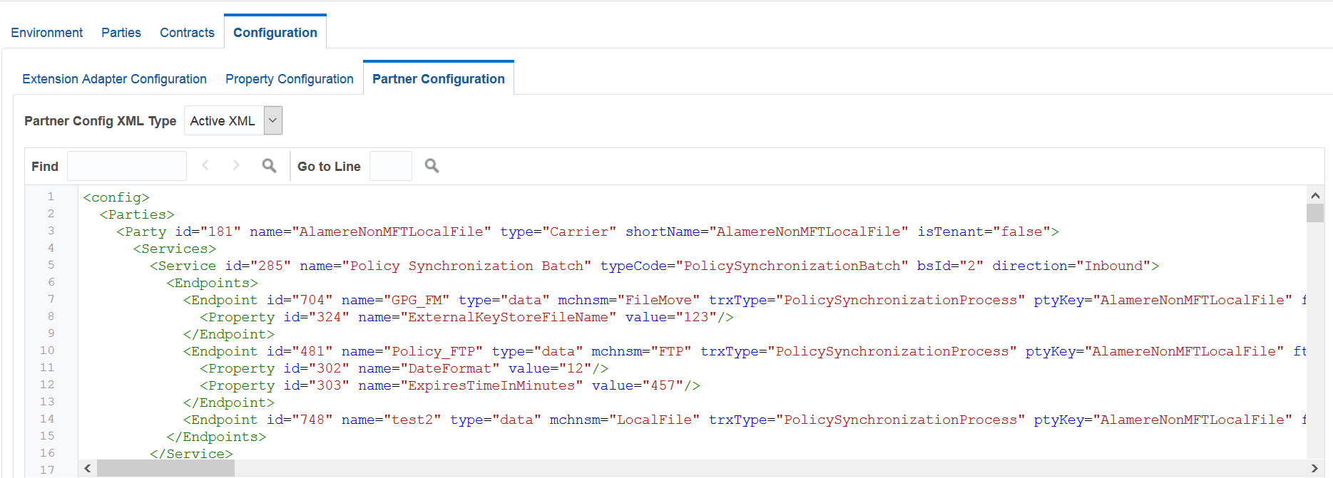
Accessing Partner Config XML
The Configuration tab allows you to access the ‘Partner Config XML’ file. All the settings and activities you perform through AdminView are reflected in this XML.
You can set the Partner Config XML to following types:
Full XML – Displays full configuration XML content.
Active XML – Displays only configurations that have been set to active.
Figure 3.1.10 - Partner Configuration Tab
Navigating through XML
You can navigate two ways in this XML:
Find – Enter the keyword that you are looking for, and click search.
Go to Line – Enter the line number where you wish to navigate.
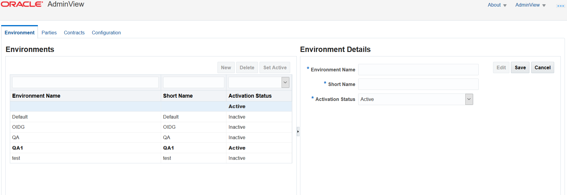
Configuring Environments
The Environment tab is selected by default upon login. This tab will allow you to create, edit, and delete environment configurations.
Creating an Environment
To create a new environment, follow the steps below:
Click ‘New’.
Enter following details under the column ‘Environment Details’. Figure 3.1.11 - Creating an Environment
Environment Name – Name of the environment you wish to create. You may use spaces and underscores in your environment name.
Short Name – A short alias or abbreviation. Short Name should start with an alphabet and no special characters are allowed except underscores.
Activation Status – Using the drop-down, set the status to Active to enable an environment or Inactive to disable it.
Click ‘Save’ once you entered the above details.
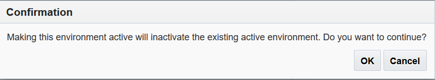
Following dialog appears if you selected the ‘Activation Status’ as ‘Active’. Figure 3.1.12 - Confirmation Dialog
If the status of an environment is inactive, it cannot be used for communication between sender and receiver parties. Environments created here will be available for selection under the Parties tab when configuring endpoints for party services.
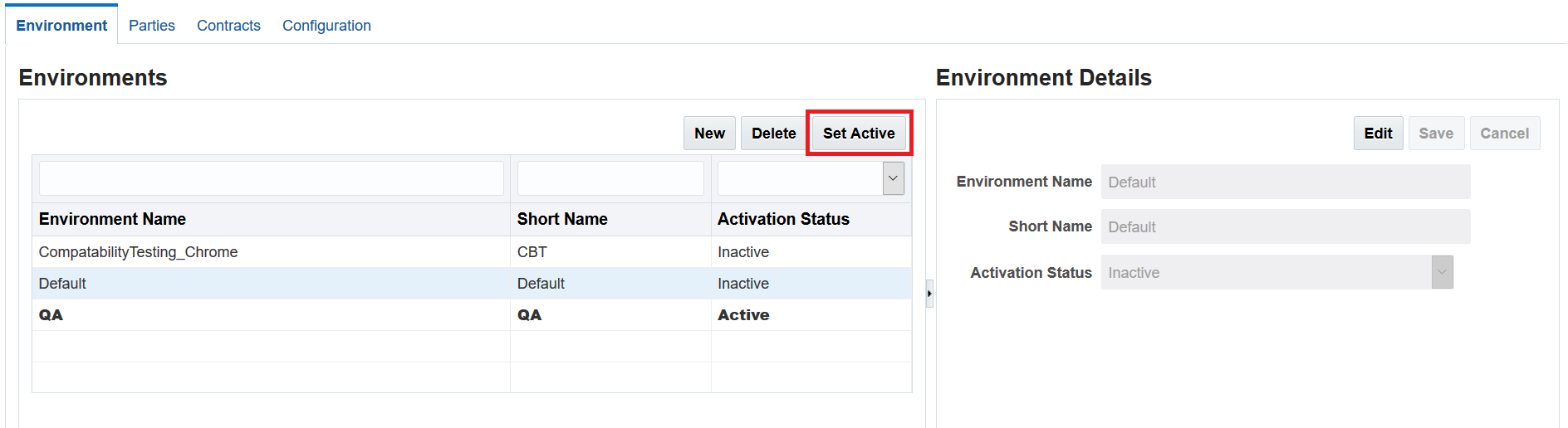
Setting an Environment as Active/Inactive
While creating an environment:
If you choose to set environment as Active, other available environment(s) will turn Inactive.
If you choose to set environment as Inactive, there will be no impact upon existing environment(s).
You may activate an environment using ‘Set Active’ button as shown below:
Figure 3.1.13 - Setting Active Environment
To activate, select the environment row you want to activate and click ‘Set Active’ button. Following dialog displays. Click ‘Ok’ to proceed.
Figure 3.1.14 - Confirmation Dialog
The activated environment is highlighted in bold fonts and ‘Activation Status’ represents ‘Active’.
Note: You may keep only one environment activated at one time. Activating another environment will set remaining environment(s) as inactive automatically.
If you want to inactivate an environment manually, you can edit them. See the ‘Editing an Environment’ topic.
Editing an Environment
To edit an existing environment, follow these steps:
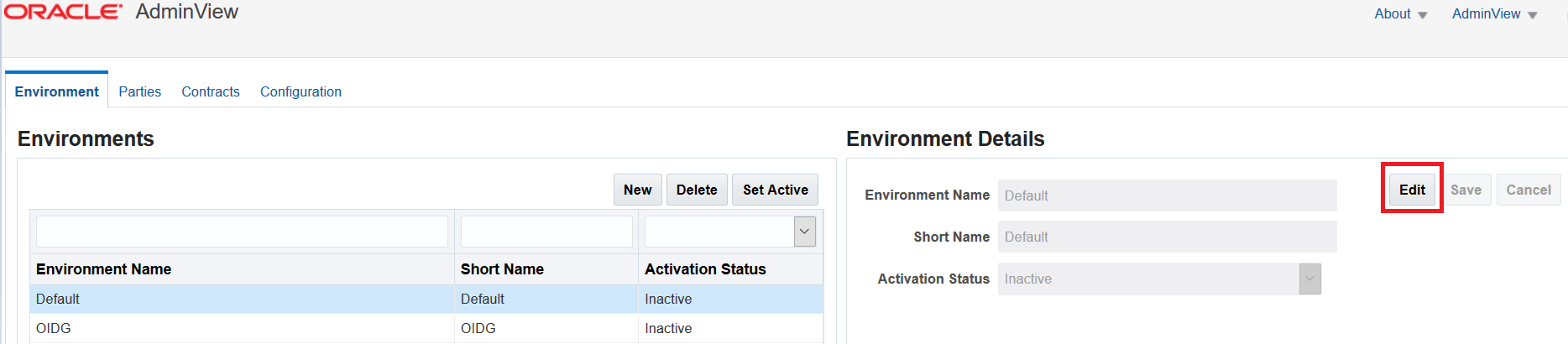
Select the row of the environment you wish to edit available in the left column. Environment details are displayed in the right column and the ‘Edit’ button is activated. Figure 3.1.15 - Editing an Environment
Click ‘Edit’.
Click ‘Save’ once you’ve completed your edits.
Deleting an Environment
To delete an environment, follow these steps:
Select the row of the environment you wish to delete available in the left column.
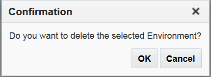
Click ‘Delete’. A pop up dialog appears for confirmation. Figure 3.1.16 - Confirmation Dialog
Click ‘Ok’ to delete the environment.
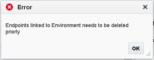
Note: Before you can delete an environment, you must first delete all endpoints linked to that environment. Endpoints are assigned to parties and are then linked to environments. You will receive an error message if you forget to delete a link between an endpoint and an environment when attempting to delete the environment.
Figure 3.1.17 - Error Dialog
Configuring Parties
The Parties tab allows you to create, edit, and delete party types that are integrated on the system. Party services and endpoints are also configured under this tab.
Creating Parties
To create a new party, follow these steps:
Click ‘New’.
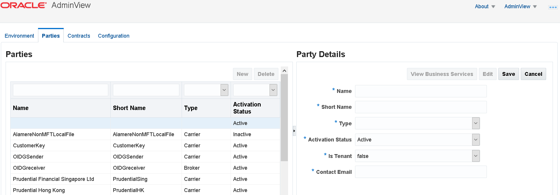
Enter following details under the column ‘Party Details’ located on the right side of the page. Figure 3.1.18 - Creating Parties
Name – Name of the party you wish to create.
Short Name – A short alias or abbreviation. Short Name should start with an alphabet and no special characters are allowed except underscores.
Type – The party type e.g. Carrier or Broker.
Activation Status – Using the drop-down, set the status to Active to enable a party or Inactive to disable a party. An Inactive status prevents any communication with a party at runtime.
Is Tenant – if set to true, only single party can be a treated as tenant at one time. Used to identify tenant among all the parties. The default value is set to false.
Contact Email – this is the email ID that will be used to communicate with notification and errors.
Click ‘Save’ once you entered above details.
Editing Parties
To edit an existing party, follow these steps:
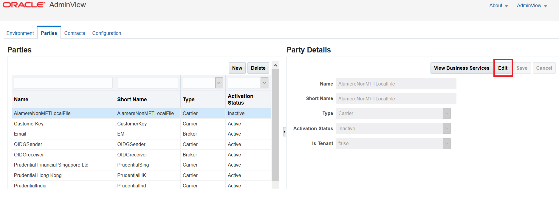
Select the row of the party you wish to edit. Party details are displayed on the right and the ‘Edit’ button is activated. Figure 3.1.19 - Editing Parties
Click ‘Edit’.
Click ‘Save’ once you’ve completed your edits.
Deleting Parties
To delete party, follow these steps:
Select the row of the party you wish to delete.
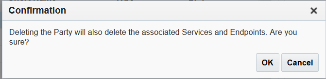
Click ‘Delete’. A pop up dialog appears for confirmation. Figure 3.1.20 - Confirmation Dialog
Click ‘Ok’ to delete the party.
Configuring Business Services for Parties
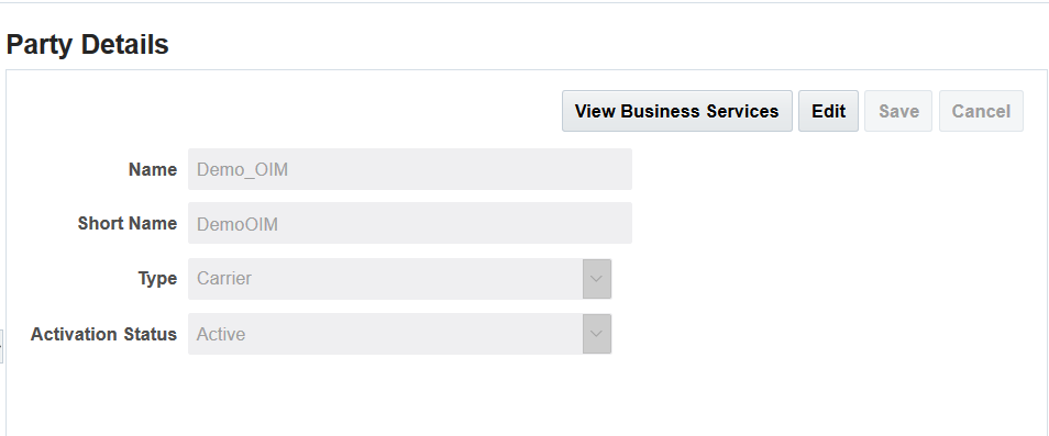
Once you created parties, you can enable them to integrate on business services provided by the system. These business services can be assigned and unassigned using the ‘View Business Services’ button available in the ‘Party Details’ area on the Parties tab.
Figure 3.1.21 - Party Details Column
This navigates you to business services page where you can create, edit, and delete business service associations.
Select the row of the party for whom you wish to create, edit, or delete service associations and click ‘View Business Services’.
Associating Business Services
To create a new business service association, follow these steps:
Click ‘New’.
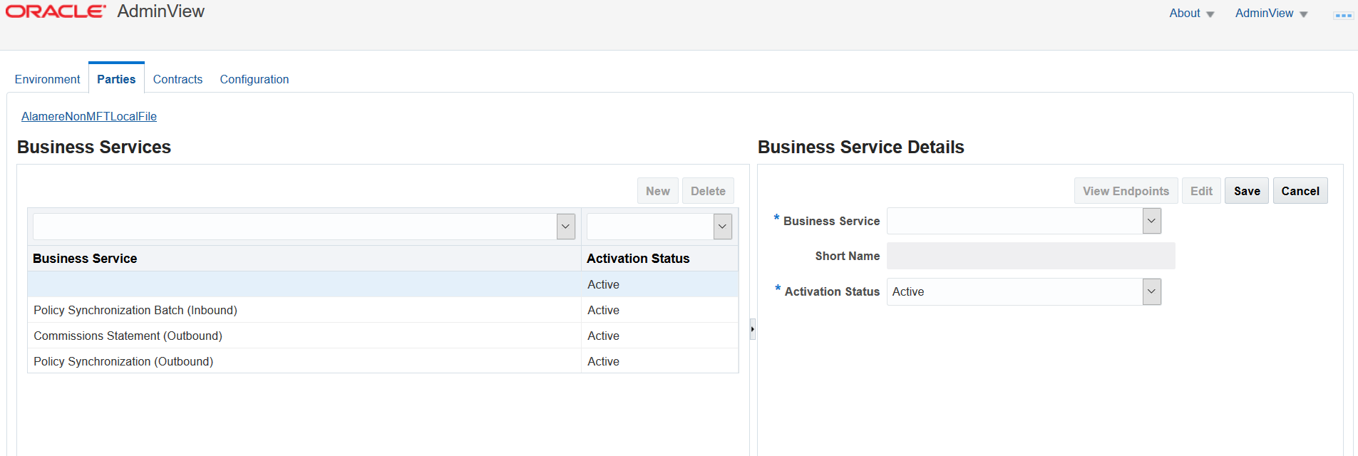
Enter following details under the column ‘Business Service Details’. Figure 3.1.22 - Associating Business Service
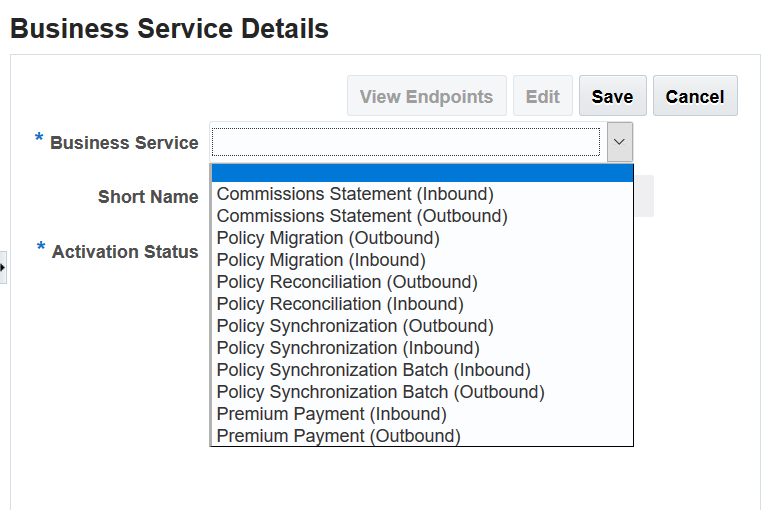
Business Service – The business service you wish to associate with the party. The options include the business services as shown in the screenshot below. Since a party is either sending data into the system (inbound) or receiving data from the system (outbound) this service direction must also be chosen. Figure 3.1.23 - Associating Business Service
Business Services
Business Service Name
Description
Commissions Statement (Inbound)
This is used to receive commission details for multiple policies from the sending party into OIDG with the intent to send them to a receiving party.
Commissions Statement (Outbound)
This is used to send commission details for multiple policies to a receiving party endpoint.
Policy Migration (Outbound)
This is used to send large batches of policies from OIDG to a receiving party to initialize the receiving system with this policy information.
Policy Migration (Inbound)
This is used to receive large batches of policies from the sending party into OIDG with the intent to initialize the receiving party system with this policy information.
Policy Reconciliation (Outbound)
This is used to send large batches of policies from OIDG to a receiving party with the intent to synchronize the sender and receiver party systems.
Policy Reconciliation (Inbound)
This is used to receive large batches of policies from the sending party into OIDG with the intent synchronize the sender and receiver party systems.
Policy Synchronization (Outbound)
This is used to send new business data or policy changes from OIDG to a receiving party endpoint.
Policy Synchronization (Inbound)
This is used to receive new business data or policy changes from a sending party into OIDG.
Policy Synchronization Batch (Outbound)
This is used to send batches of new business data or policy changes from OIDG to a receiving party endpoint.
Policy Synchronization Batch (Inbound)
This is used to receive batches of new business data or policy changes from a sending party into OIDG.
Premium Payment (Outbound)
This is used to send premium payment data for a policy to a receiving party endpoint.
Premium Payment (Inbound)
This is used to receive premium payment data for a policy from the sending party into OIDG with the intent to send it to a receiving party.
Activation Status – Using the drop-down, set the status to Active/ Inactive to enable/ disable a business service association. An Inactive status prevents any communication over this particular business service association for the indicated parties at runtime.
Click ‘Save’ once you entered the above details.
Editing a Business Service Association
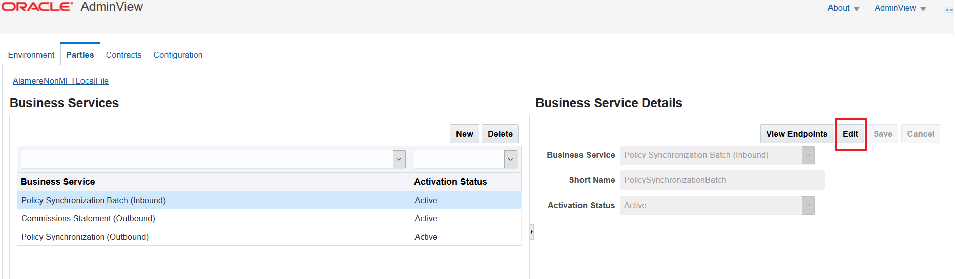
To edit a business service association, follow these steps:
Select the row of the business service association you wish to edit. Business service details are displayed on the right and the ‘Edit’ button is activated. Figure 3.1.24 - Editing Business Service Association
Click ‘Edit’ and make the changes.
Click ‘Save’ once you’ve completed your edits.
Deleting a Business Service Association
To delete business service association, follow these steps:
Select the row of the business service association you wish to delete.
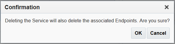
Click ‘Delete’. A pop up dialog appears for confirmation. Figure 3.1.25 - Confirmation Dialog
Click ‘Ok’ to delete the service association.
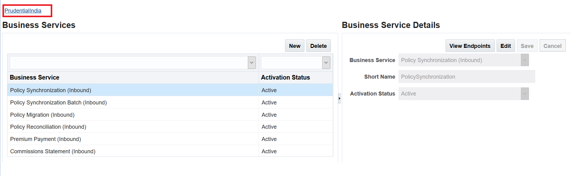
Note: To go back to the Parties page, click the hyperlink as shown in the screenshot below.
Figure 3.1.26 - Breadcrumb Navigation
Configuring Endpoints for a Party’s Business Service Association
Endpoints are a means to integrate party services with OIDG business services. All the information required to access a party’s service are defined in endpoints. This includes information like URLs, port numbers, folder locations, etc.
Once you’ve created parties and associated business services to them, you can then create, edit, or delete endpoints for each of the business services. Endpoint configurations can be different in each environment that you’ve created. The environments that you created will be available for selection during endpoint configuration.
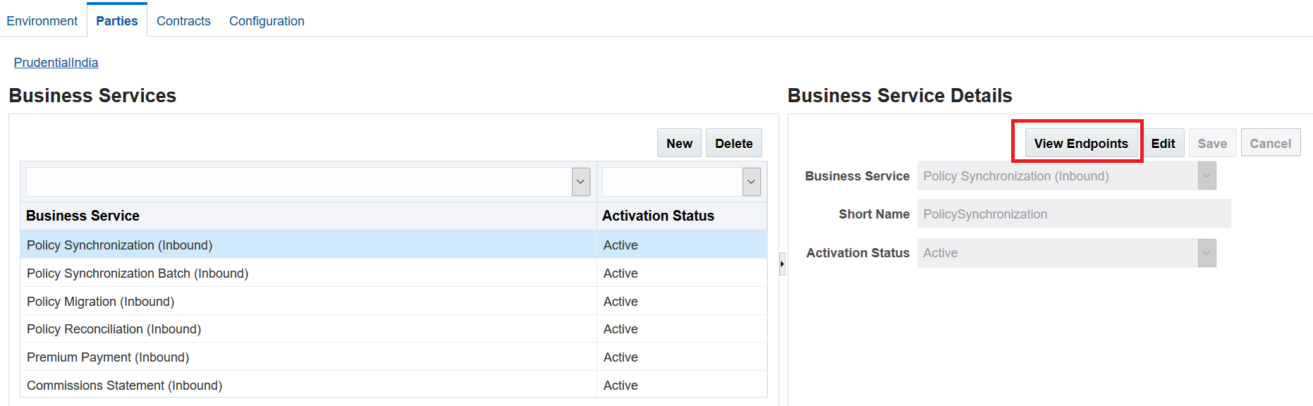
To configure endpoints, select row of the business service then click the ‘View Endpoints’ button available under ‘Business Service Details’ located on the right side of the page.
Figure 3.1.27 - View Endpoints Button
This navigates you to Endpoints page where you can create, edit, and delete endpoints.
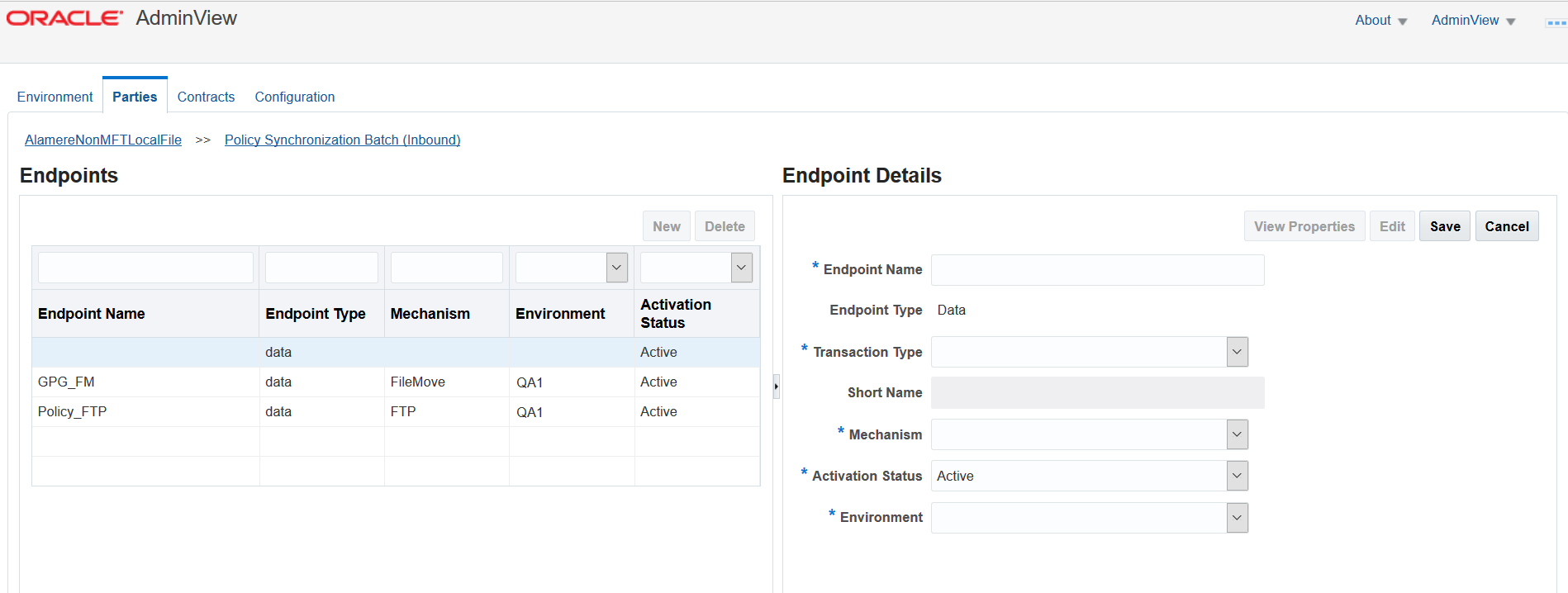
Creating an Endpoint: Inbound Services
To create a new Endpoint for inbound transactions, follow these steps:
Click the ‘New’ button.
Enter the Endpoint Name, select Transaction Type, Environment and Mechanism using the drop-down as shown in the following table. Figure 3.1.28 - Creating an Endpoint (Inbound Services)
Fields
Description
Endpoint Name
An endpoint name must be unique for a particular transaction type
Endpoint Type
By default it is set as ‘data’
Transaction Type
Transaction type can be set to one of the following
Client Data Submit – submit customer data only
Policy Submit – submit full policy data
Get Policy Status – query to see if policy already exists in the receiving system
Note: Transaction types may vary on the business service type and direction selected. You may see one or all transaction types available based on the business service selected. See the list of available business services here Business Services.
Mechanism
There are four mechanisms for any inbound transaction
FTP
FileMove
LocalFile
Webservice
By default, the mechanism field is blank. Based on the mechanism selected, other fields will display.
See the Transaction Mechanisms topic in Overview chapter for more details.
Adapter
This field is available only for outbound data endpoints.
Select the adapter using the drop-down
Activation Status
Active or Inactive
Environment
One of the environments created on the environments tab
Click ‘Save’ once you entered the above details.
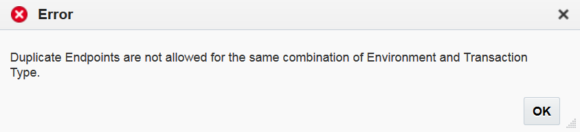
Note:
AdminView does not allow you to create duplicate endpoints for the same combination of environment and transaction type. Following error message displays if you choose the same combination of environment and transaction type :
Figure 3.1.29 - Error Dialog
Transaction Mechanisms
If you are creating an endpoint for inbound services, you will have Webservices or all four types of transaction mechanisms i.e. FTP, FileMove, LocalFile and Webservice to choose depending on type of service.
FTP Transaction Mechanism
This mechanism is used to read and move files from an FTP server. If you selected the FTP mechanism while creating an endpoint, the following fields are displayed:
Fields
Description
FTP Host
FTP server host
Port
FTP server port
FTP Req Dir
The folder path from where application will pull files
Request Folder
The folder path where request files are placed
Error Folder
The folder path where error files are placed
Result Folder
The folder path where batch error result/ xml files are stored initially
Backup Folder
The folder path where files are backed up after successful processing
Delete Remote File
Selecting "True" will delete the files from staging folder after processing
User Name
User name to connect to FTP Req Dir
Password
Password to connect to FTP Req Dir
FTP Type
Type of the FTP. We are supporting SFTP
FTP Error Directory
Enter FTP error directory path
FTP Result Directory
Enter FTP result directory path
Out Directory
Enter Out directory path
GPG Needed
If set to true, ‘Enable GPG Digital Signature’ and ‘GPG user password’ fields are displayed. This is required when sender party is sending request in GPG encrypted format.
Enable GPG Digital Signature
Setting as ‘true’ enables digital signature functionality. A digital signature is used to certify and timestamp a document. It is used to identify sending party.
When it is set to false, the signature validation is ignored though it is present on the request files.
GPG User Password
Enter the user password
FileMove Transaction Mechanism
This mechanism is used to read and move files from a remote or local server folder location. If you selected the FileMove mechanism while creating an endpoint, the following fields are displayed:
Fields
Description
FileMove Req Dir
The folder path from where application will pull files within application server
Request Folder
The folder path where request files are placed
Error Folder
The folder path where error files are placed
Result Folder
The folder path where batch error result/ xml files are stored initially
Backup Folder
The folder path where files are backed up after successful processing
Delete Remote File
Selecting "True" will delete the files from staging folder after processing
GPG Needed
If set to true, ‘Enable GPG Digital Signature’ and ‘GPG user password’ fields are displayed. This is required when sender party is sending request in GPG encrypted format.
Enable GPG Digital Signature
Enables digital signature functionality. A digital signature is used to certify and timestamp a document.
When it is set to false, the signature validation is ignored though it is present on the request files.
GPG User Password
Enter the user password
LocalFile Transaction Mechanism
This mechanism is used to read files from a local OIDG application folder. If you selected the LocalFile mechanism while creating an endpoint, the following fields are displayed:
Fields
Description
Request Folder
The folder path where request files are placed
Error Folder
The folder path where error files are placed
Result Folder
The folder path where batch error result/ xml files are stored initially
Backup Folder
The folder path where files are backed up after successful processing
GPG Needed
If set to true, ‘Enable GPG Digital Signature’ and ‘GPG user password’ fields need to be entered. This is required when sender party is sending request in GPG encrypted format.
Enable GPG Digital Signature
Enables digital signature functionality. A digital signature is used to certify and timestamp a document.
GPG User Password
Enter the user password
Webservice Transaction Mechanism
This mechanism allows parties to communicate their services with web-service supported applications. If you selected Webservice mechanism while creating an endpoint, the following fields are displayed:
Fields
Description
URL
Web service URL
Port
Web service Port
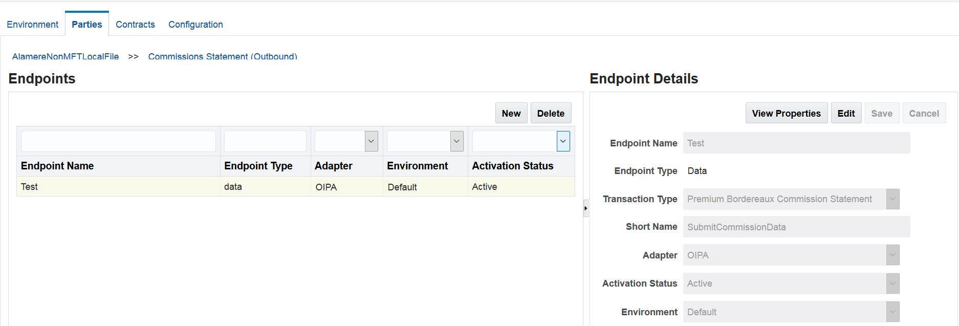
Creating an Endpoint: Outbound Services
To create a new endpoint for outbound transactions, follow these steps:
Click the ‘New’ button.
Enter the Endpoint Name and type, select Transaction Type, Adapter, Activation Status and Environment using the drop-down as shown in the following table: Figure 3.1.30 - Creating an Endpoint (Outbound Services)
Fields
Description
Endpoint Name
Name of endpoint
Endpoint Type
By default it is set as ‘data’
Transaction Type
Transaction type can be set to one of the following:
Client Data Submit – submit customer data only
Policy Submit – submit full policy data
Get Policy Status – query to see if policy already exists in the receiving system
Note: Transaction types may vary on the business service type and direction selected. You may see one or all transaction types available based on the business service selected. See the list of available business services here Business Services.
One of the environments created on the environments tab
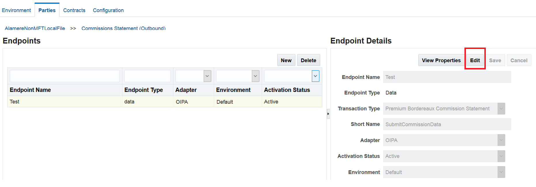
Editing an Endpoint
To edit an existing endpoint, follow these steps:
Select the row of the endpoint you wish to edit. Endpoint details are displayed on the right and the ‘Edit’ button is activated. Figure 3.1.31 - Editing an Endpoint
Click ‘Edit’ and make the changes.
Click ‘Save’ once you’ve completed your edits.
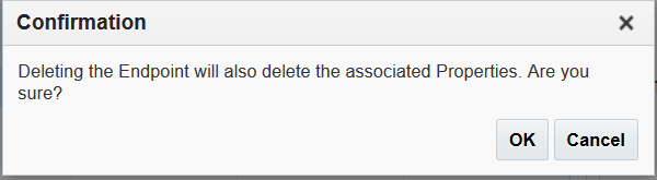
Deleting an Endpoint
To delete an endpoint, follow these steps::
Select the row of the endpoint you wish to delete.
Click ‘Delete’. A pop up dialog appears for confirmation. Figure 3.1.32 - Confirmation Dialog
Click ‘Ok’ to delete endpoint.
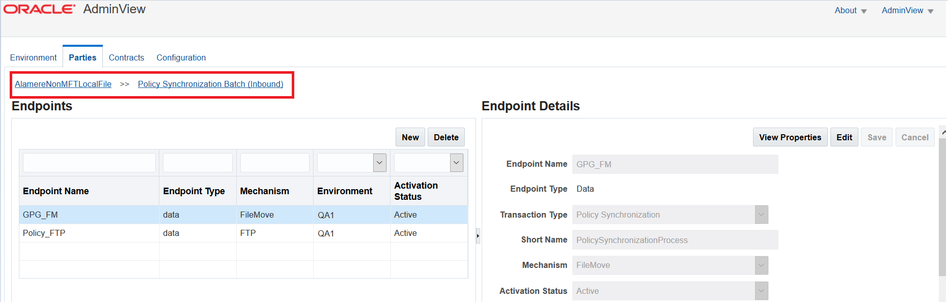
Note: If you are on the Endpoints page, you may navigate to back to the Parties or Business Services pages using the breadcrumb links available at the top of the page as shown in the screenshot below.
Figure 3.1.33 - Breadcrumbs
Configuring Properties for Endpoints
Endpoint properties allow for fine-grained value specification of integration endpoint details. They can also help receiving party systems determine how to handle messages they are receiving from OIDG. OIDG uses system defined properties to capture details it needs about the endpoint transport and security needs. Custom properties can be used to transmit values. The receiving system might need to better handle messages coming from OIDG.
System Properties
Endpoint Property Name
Values
Purposes and Dependency
Use Legacy WS Caller Process
True or False. Defaults to False.
Setting ‘True’ will call the integrated web service values defined by client’s WSDL.
Setting ‘False’ will call the integrated web service values defined by OIDG’s own WSDL.
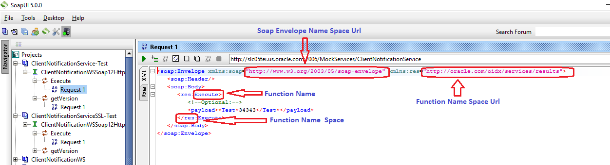
WS Function name refer below screen
(required if the WS caller value is set to ‘True’)
Function Name Space
Example: “res”
WS Function name space refer below screen
(required if the WS caller value is set to ‘True’)
Function Type
Example: “xml”
Payload is available in xml format
(required if the WS caller value is set to ‘True’)
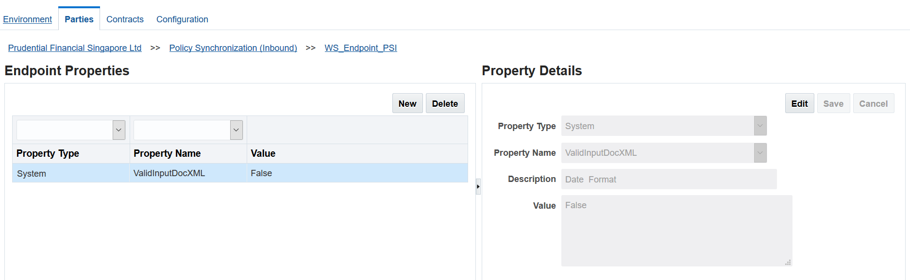
Valid Input Doc XML
True or False. Defaults to False.
Setting this property will validate the payload xml file
(required if the WS caller value is set to ‘True’)
Input Params
Example: “<payload><![CDAT[%1$s]]></payload>”
These values are input parameters to the function name, refer below screen
(required if the WS caller value is set to ‘True’)
Need SSL
True or False. Defaults to False.
Set to ‘True’ if you wish to integrate secure web service
Date Format
Example: "YYYY-MM-dd'T'HH:mm:ss.SSS'Z'"
It’s a web service soap date time format of client WS (required if the WS caller value is set to ‘True’)
Expires Time In Minutes
Example: 5
Client web service expires time in minutes
(required if the WS caller value is set to ‘True’)
Time Zone
Example: "UTC"
Time zone where client web service deployed
(required if the WS caller value is set to ‘True’)
Need Ext KeyStore
True or False. Defaults to False.
Set to ‘True’ if you have client web service trust store file
External KeyStore File Type
Example: “JKS”
Key Store file extension type
External KeyStore File Name
Example: “LocalKeyStore.jks”
Key Store file name with extension
External KeyStore Location Path
Example: “/scratch/idxAdmin/config”
Key Store location path where key store file is copied
External KeyStore Password
Key store password
External KeyStore Password Encrypted
True or False. Defaults to False.
Set to ‘True’ if the key store password is encrypted
Need Ext TrustStore
True or False. Defaults to False.
Set to ‘True’ if you have client web service trust store file
External TrustStore File Type
Example: “JKS”
Trust Store file extension type
External TrustStore File Name
Example: “LocalKeyStore.jks”
Trust Store file name with extension
External TrustStore Location Path
Example: “/scratch/idxAdmin/config”
Trust Store location path where trust store file is copied
External TrustStore Password
Trust Store password
External TrustStore Password Encrypted
True or False. Defaults to False.
Trust Store password in encrypted is true
External WebService SSL Provider
Example: TLSv1.2
Client web service SSL provider
External WebService SSL Cipher Suite
Example: TLS_ECDHE_RSA_WITH_AES_128_CBC_SHA
Client web service SSL cipher suite
Example: SOAP Property Sources.
Figure 3.1.34 - SOAP Property Sources
Example: SOAP Endpoint Property Entries.
Figure 3.1.35 - SOAP Endpoint Property Entries
Custom Properties
Users can create any name-value pair needed. These are passed to the receiving system, which can then act upon those specifications or ignore them.
Custom Properties for OIPA Integration
Configuration of OIDG’s built-in OIPA integration support requires the definition of OIPA-specific custom properties for the following endpoint types.
Policy Synchronization
Policy Synchronization Batch
Policy Migration
Premium Payment
Commission Statement
The Property Name that need to be configured depends on the endpoint’s target i.e. DataIntake or FileReceived web service. Refer to the following table:
OIPA Target
Property Name
Value
Data Intake
oipa.requestType
Must be “DataIntake”
oipa.dataintake.groupCustomerNumber
The group customer number defined by the target OIPA implementation.
oipa.profileName
The profile name defined by the target OIPA implementation.
FileReceived
web service
oipa.requestType
Must be “FileReceived”
oipa.filereceived.fileId.delta
The file ID for delta (i.e., “new”) policy requests (SubmitPolicyData only)
oipa.filereceived.fileId.change
The file ID for change policy requests (SubmitPolicyData only)
oipa.filereceived.fileId.premium
The file ID for premium payment requests (SubmitPremiumData only)
oipa.filereceived.fileId.commission
The file ID for premium commission requests (SubmitCommissionData only)
Creating a Custom Property for an Endpoint
To create an endpoint property follow these steps:
Click the ‘View Properties’ button located under endpoint details column.
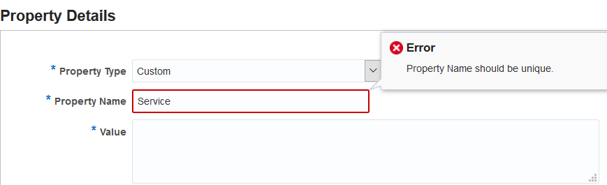
Click ‘New’.
Select ‘Custom’ for the ‘Property Type’. Note: Property names must be unique. Duplication of property names is not permitted and results in the following error. Figure 3.1.36 - Unique Property Name
Enter a value and click ‘Save’.
Editing an Endpoint Property
To edit an existing endpoint property, follow these steps:
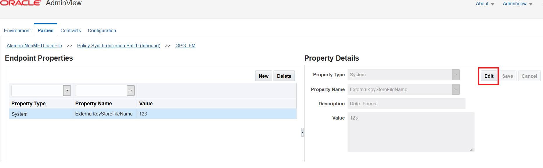
Select the row of the endpoint property you wish to edit available in the left column. Endpoint property details are displayed in the right column and the ‘Edit’ button is activated. Figure 3.1.37 - Editing an Endpoint Property
Click ‘Edit’ and make the changes.
Click ‘Save’ once you’ve completed your edits.
Deleting an Endpoint Property
To delete an endpoint property, follow these steps::
Select the row of the endpoint property you wish to delete.
Click ‘Delete’. A pop up dialog appears for confirmation. Figure 3.1.38 - Confirmation Dialog
Click ‘Ok’ to delete the endpoint property.
Configuring Contracts
The Contracts tab allows you to create, edit, and delete the details for mapping the inbound services associated with a sender party to the outbound endpoints associated with the receiving party.
Creating Contracts
To create a new contract, follow these steps:
Click ‘New’.
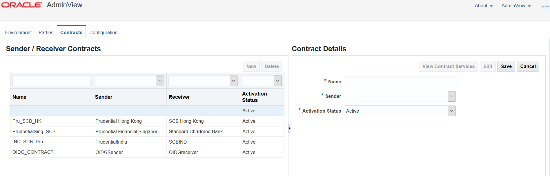
Enter following details under ‘Contract Details’ located at the right side of the ‘Sender / Receiver Contract’ page. Figure 3.1.39 - Creating Contracts
Name – Enter name of the contract you wish to create.
Sender – Select the sender party via the pre-populated drop-down.
Receiver – Select the receiver party via the pre-populated drop-down. By default, the receiver field is not displayed. Once you select the sender party through dropdown, then the receiver field is displayed accordingly.
Activation Status – Select the status Active/ Inactive.
Click ‘Save’ once you entered the above details.
Editing Contracts
To edit an existing contract, follow these steps:
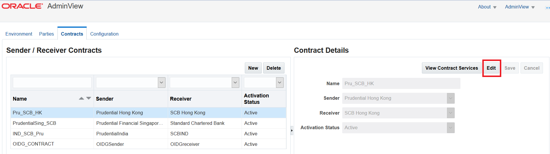
Select the row of the contract you wish to edit. The contract details are displayed on the right with the ‘Edit’ button activated. Figure 3.1.40 - Editing Contracts
Click ‘Edit’ and make the changes.
Click ‘Save’ once you’ve completed editing.
Deleting Contracts
To delete a contract, follow the steps:
Select the row of the contract you wish to delete.
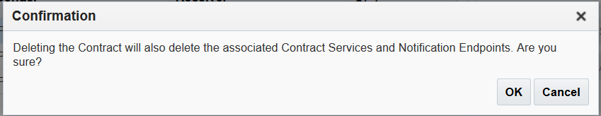
Click ‘Delete’. A pop up dialog appears for confirmation. Figure 3.1.41 - Confirmation Dialog
Click ‘Ok’ to delete the contract.
Configuring Contract Services
Once you created a sender/ receiver contract, you can then map inbound business services to outbound receiver party endpoints.
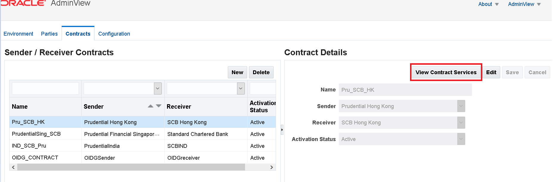
Figure 3.1.42 - View Contract Services
To start, select the row of the contract you wish to create, edit or delete contract services for and then click the ‘View Contract Services’ button under ‘Contract Details’.
Creating Contract Services
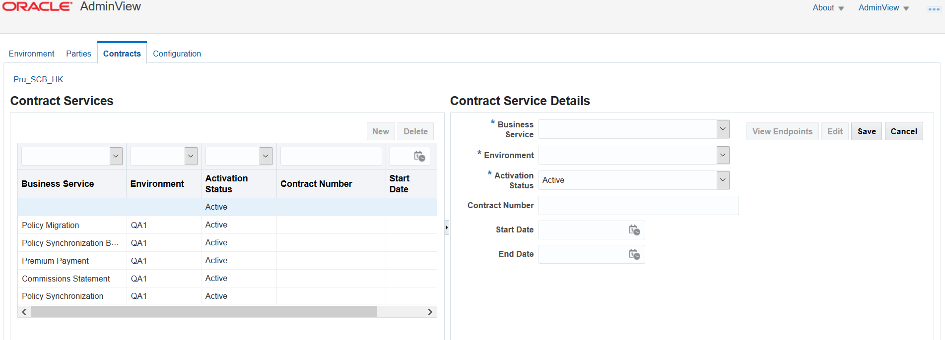
To create a new contract service, follow these steps:
Click ‘New’ under Contract Services. Figure 3.1.43 - Creating Contract Service
Enter the following details under ‘Contract Service Details’.
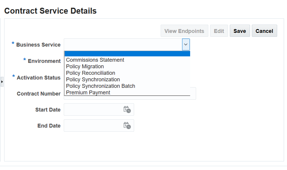
Business Services – Select any service through drop-down option. Figure 3.1.44 - Business ServicesSee Business Services for a description of these services.
Environment – Specify the Environment to which you wish to map this service contract. The Environment drop-down will be pre-populated with the environments you created on the Environments Tab.
Activation Status – Select status Active/ Inactive.
Contract Number – A unique alphanumeric identifier, usually provided by the contract owner (Carrier or Distributor), that represents a contractual agreement between sender and receiver parties to integrate on specific transaction types. This can be used to validate communication at runtime but is optional.
Specify a desired Start and End date for the contract service (optional).
Click ‘Save’ once you’ve entered the above details.
Editing Contract Services
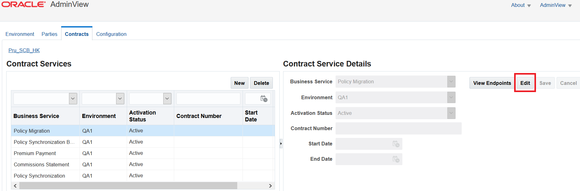
To edit an existing contract service, follow these steps:
Select the row of the contract service you wish to edit. Under Contract Service Details, the ‘Edit’ button is activated. Figure 3.1.45 - Editing Contract Services
Click ‘Edit’ and make the changes.
Click ‘Save’ once you’ve completed editing.
Deleting Contract Services
To delete a contract service, follow the steps:
Select the row of the contract service you wish to delete.
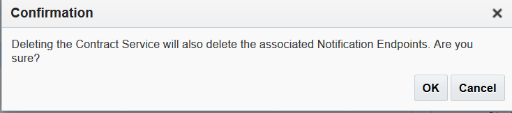
Click ‘Delete’. A pop up dialog appears for confirmation. Figure 3.1.46 - Confirmation Dialog
Click ‘Ok’ to delete the contract service.
Note: To go back to the ‘Sender / Receiver Contracts’ page, click the hyperlinked breadcrumb at the top of the page as indicated in the screenshot below.
Figure 3.1.47 - Breadcrumb
Associating Endpoints to Contract Services
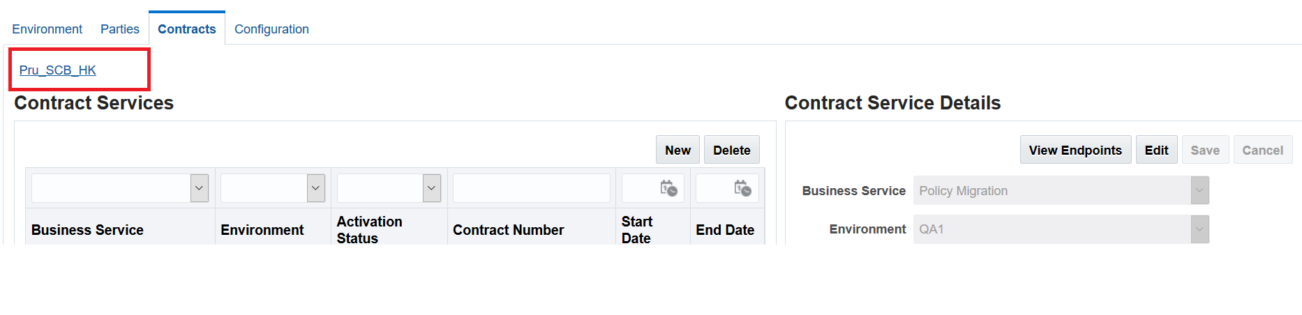
Once you’ve created a contract service, endpoints are associated to it automatically. These endpoints can be viewed using the ‘View Endpoints’ button under ‘Contract Service Details’. This navigates you to the Endpoints page where you can view the endpoints for a particular contract.
Select the row of the contract you for which you wish to view endpoint(s) to and click the ‘View Endpoints’ button.
Figure 3.1.48 - View Endpoint in Contract Service Details
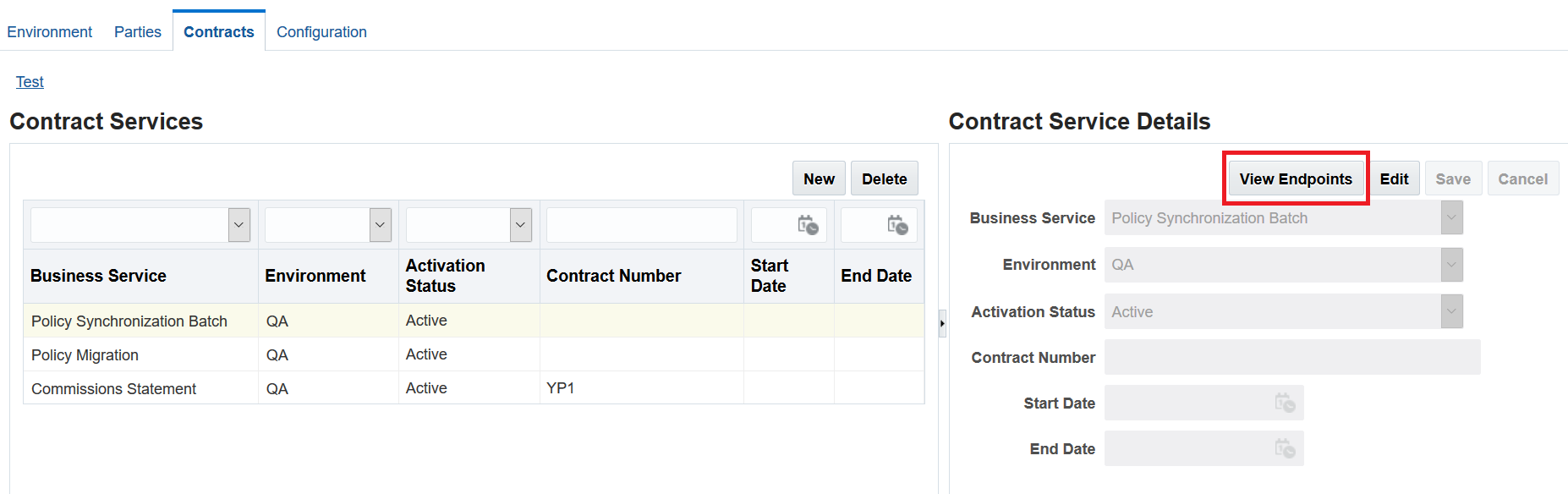
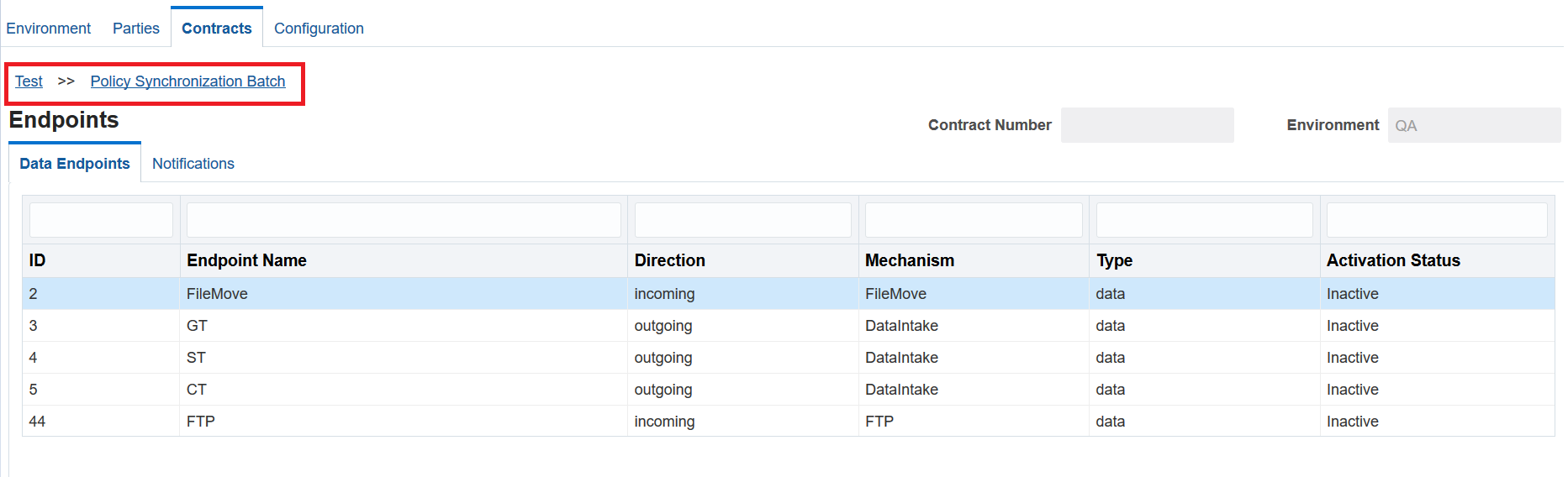
The Endpoints page displays a list of endpoints available for the selected contract service. The system automatically determines which endpoints are appropriate for the selected sender, receiver, and business service based on your prior configuration settings.
Figure 3.1.49 - Data Endpoints Tab
Note: From the Endpoints page, you can navigate back to the Sender/Receiver Contracts or Contract Services pages by clicking on the breadcrumb links available at the top of the page as indicated in the screenshot below.
Figure 3.1.50 - Breadcrumbs
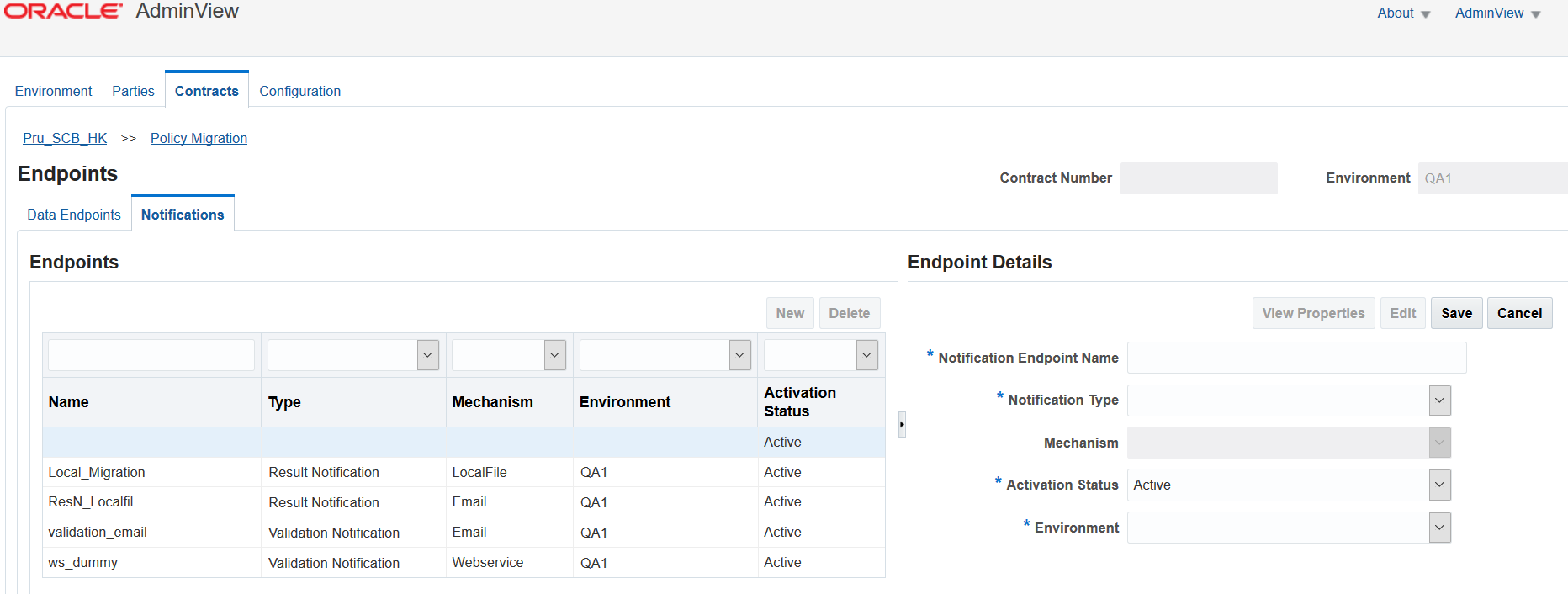
Configuring Notifications
The notification tab allows you to configure validation and result notifications that will be sent out to sender and/or receiver parties for specified business service types and events. To receive these notifications, sender and receiver parties must have notification endpoints specified. These can be web-services, file locations, and emails.
Note: Notification tab is available only for Policy synchronization Batch, Policy Migration, Policy Reconciliation & Commission Statement business services.
Creating Notification Endpoint
To create a new notification endpoint specification, follow these steps:
Enter a unique name for the notification endpoint.
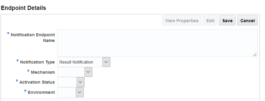
Select a notification type. There are two types of notifications.
Result Notification
Validation Notification
Figure 3.1.52 - Notification Type
Select a mechanism by which the notification is to be sent. The following options are available:
Email
LocalFile
FTP
Webservice
Select an activation status. Active or Inactive.
Select an environment. Environments that were previously created under the ‘Environment’ tab are displayed here.
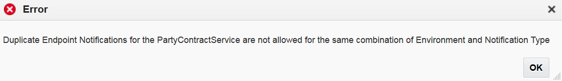
Note:
AdminView does not allow you to create duplicate endpoints for the same combination of environment and notification type. Following error message displays if you choose the same combination of environment and notification type:
Figure 3.1.53 - Error Dialog
Based on the mechanism type chosen, additional fields will display.
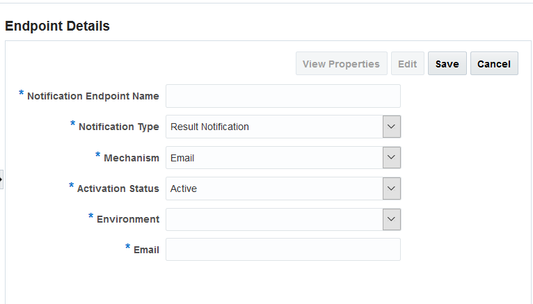
Selecting ‘Email’ displays the following:
Figure 3.1.54 - Mechanism Email
Enter an email address. You may enter multiple e-mails separated by semicolon (;).
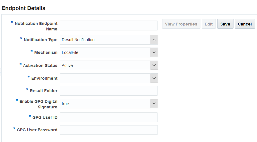
Selecting ‘LocalFile’ displays the following:
Figure 3.1.55 - Mechanism LocalFile
Enter Result Folder location.
Set the value true/false using the ‘Enable GPG Digital Signature’ drop-down. Setting the value to ‘true’ displays two additional fields. Enter the GPG User ID and Password and click ‘Save’.
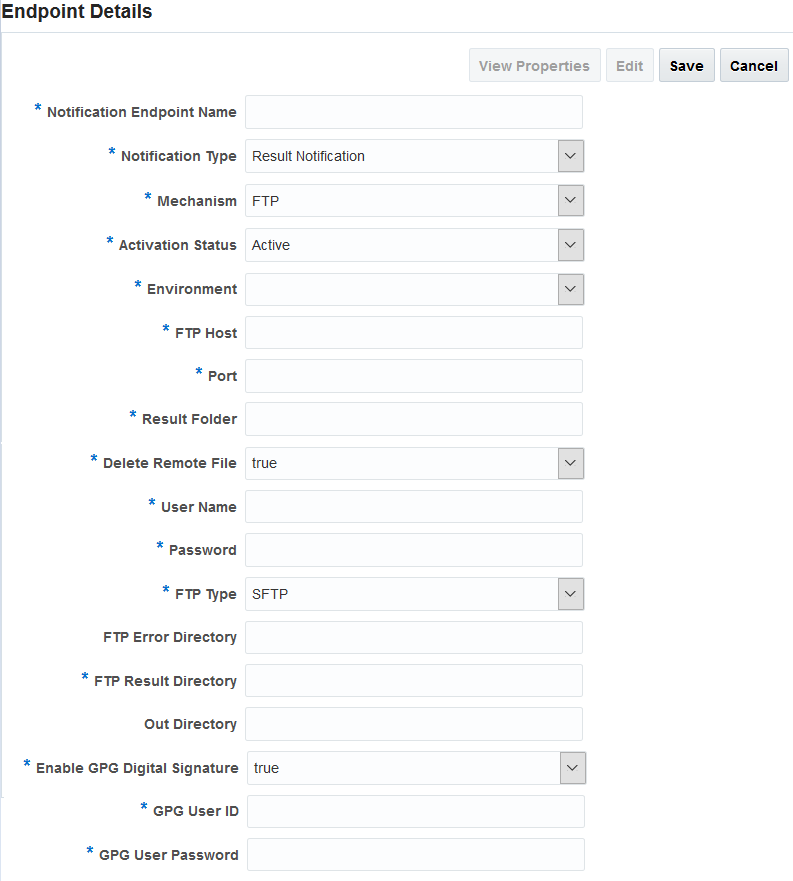
Selecting ‘FTP’ displays the following:
Figure 3.1.56 - Mechanism FTP
Fields
Description
FTP Host
FTP server host
Port
FTP server port
Result Folder
The folder path where batch error result/ xml files are stored initially.
Delete Remote File
Selecting "True" will delete the files from staging folder after processing.
User Name
User name to connect to FTP Req Dir
Password
Password to connect to FTP Req Dir
FTP Type
Type of the FTP. We are supporting SFTP, FTP, AUTH-SSL, AUTH-TSL, IMP-SSL-FTP, IMP-TSl and IMP-TSL types.
FTP Error Directory
Enter FTP error directory path
FTP Result Directory
Enter FTP result directory path
Out Directory
Enter Out directory path
Enable GPG Digital Signature
If set to true, GPG user ID and GPG User Password fields needs to be entered. This is required when digitally signed reports are send to the sender party.
GPG User ID
Enter the user ID
GPG User Password
Enter the user password
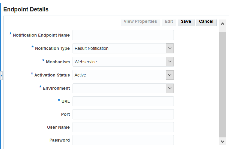
Selecting ‘Webservice’ displays the following:
Figure 3.1.57 - Mechanism Webservice
Fields
Description
URL
FTP server host
Port
FTP server port
User Name
Enter a user name
Password
Enter a password to connect
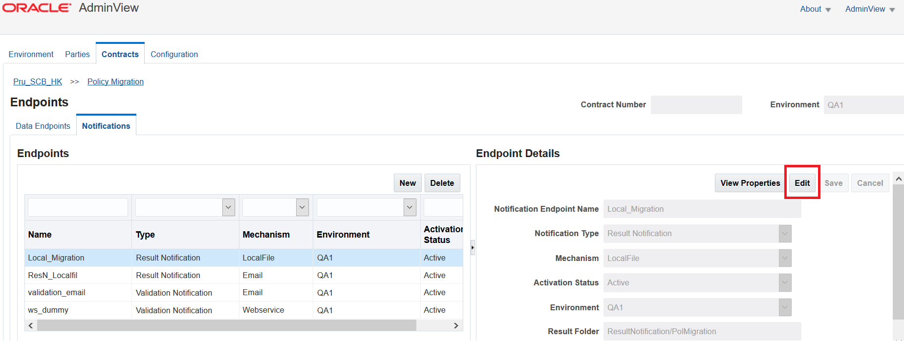
Editing a Notification Endpoint
To edit an existing notification endpoint, follow these steps:
Select the row of the endpoint you wish to edit. Endpoint details are displayed and the ‘Edit’ button is activated. Figure 3.1.58 - Editing Notification Endpoint
Click ‘Edit’ and make the changes.
Click ‘Save’ once you’ve completed editing.
Deleting a Notification Endpoint
To delete an endpoint, follow the steps:
Select the row of the notification endpoint you wish to delete.
Click ‘Delete’. A pop up dialog appears for confirmation. Figure 3.1.59 - Confirmation Dialog