Oracle SD-WAN Firewall Configuration
The Oracle SD-WAN Firewall includes Filter Policies and NAT examples to help the user understand how to configure the firewall in certain topologies and configurations.
Oracle SD-WAN Firewall Overview
Beginning in APN 5.2 GA, Oracle provides a stateful firewall built into the Oracle SD-WAN application. The firewall allows policies between user-defined zones and Oracle SD-WAN Edge services. The firewall also supports Static NAT and Dynamic NAT (PAT & Port-Forwarding). Additional firewall capabilities include:
- Filter traffic flows between zones.
- Filter traffic between Oracle SD-WAN APN services within a zone.
- Filter traffic between Oracle SD-WAN APN services that reside in different zones.
- Define filter policies to allow, deny, and reject flows.
- Filter traffic between Oracle SD-WAN APN services at a site.
- Track flow state for selected flows.
- Global Filter Policy Templates.
- Provide Static Network Address Translation (Static NAT).
- Provide Dynamic Network Address Translation (Dynamic NAT):
- Port Address Translation (PAT).
- Port-Forwarding.
To simplify the configuration process, the firewall policies can be created at a Global level. The Global configuration consists of Pre-Appliance and Post-Appliance site Policy Templates. These templates can be applied to all sites in the APN globally. This document will provide a detailed explanation of these capabilities as well as specific configuration examples for the most commonly used Firewall topologies.
Zones
The user can configure zones in the network and define policies to control how traffic enters and leaves zones. By default, the system creates and automatically applies the following zones:
- Internet_Zone—Applies to traffic to or from an Internet service using a Trusted interface.
- Untrusted_Internet_Zone—Applies to traffic to or from an Internet service using an Untrusted interface.
- Default_LAN_Zone—Applies to traffic to or from an object with a configurable zone, where the zone has not been set.
Users can create their own zones and assign them to the following types of objects:
- Virtual Network Interfaces (VNI)
- Intranet Services
- LAN GRE Tunnels
- LAN IPsec Tunnels
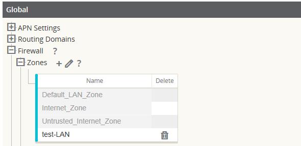
The following figure shows that there are three zones pre-configured for the user. Additionally, users can create their own zones as required. In this example, the zone “test-LAN” was a user created one. It is assigned to the Virtual Interface of the bypass segment (ports 1 and 2) of the Oracle SD-WAN Appliance.
Figure 5-1 Firewall Zones
The source zone of a packet is determined by the service or VNI a packet is received on. The only exception to this is Conduit traffic. When traffic enters a Conduit, packets are marked with the zone that originated the traffic and that source zone is carried through the Conduit. This allows the receiving end of the Conduit to make a policy decision based on the original source zone before it entered the Conduit.
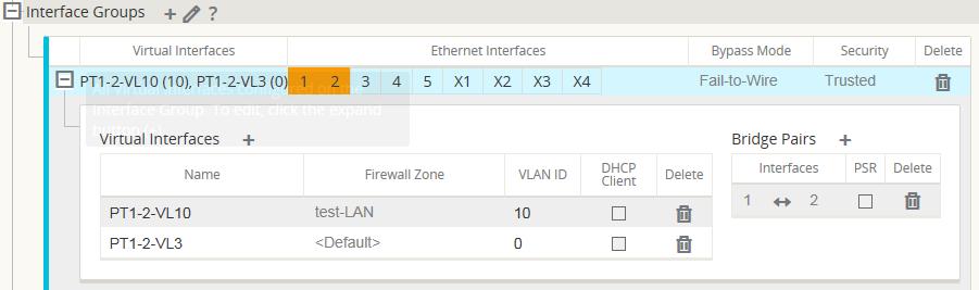
For example, a network administrator may want to define polices so that only traffic from VLAN 30 at Site A is allowed to enter VLAN 10 at Site B. The administrator can assign a zone for each VLAN and create policies that permit traffic between these zones and blocks traffic from other zones. Figure 2 shows how a user would assign the "test-LAN" zone to VLAN 10. In this example, the "test-LAN" zone was previously defined by the user in order to assign it to Virtual Interface "PT1-2-VL10".
Figure 5-2 Interface Groups
The destination zone of a packet is determined based on the destination route match. As a Oracle SD-WAN Appliance looks up the destination subnet in the route table, the packet will match a route, which has a zone assigned to it.
To state this information again:
- Source zone
- Non-Conduit: Determined via the VNI packet was received on.
- Conduit: Determined via source zone field in packet flow header. (VNI the packet was received on at source site)
- Destination zone
- Determined via destination route lookup of packet.
Routes shared with remote sites in the APN maintain information about the destination zone, including routes learned via a dynamic routing protocol (BGP, OSPF). Using this mechanism, zones gain global significance in the APN and allow end-to-end filtering within the APN.
The use of zones provides a network administrator an efficient way to segment network traffic based on customer, business unit, or department.
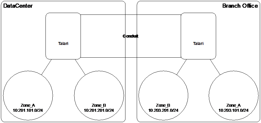
The capability of the Oracle SD-WAN firewall allows the user to filter traffic between services within a single zone, or to create policies that can be applied between services in different zones, as shown in the following figure. In the example below, we have Zone_A and Zone_B, each of which has a LAN VNI.
Figure 5-3 Zone Diagram
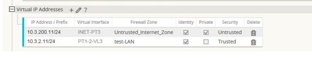
The following figure displays the inheritance of zone for a VIP from its assigned VNI.
Figure 5-4 Zone Inheritance
Policies
Policies provide the ability to allow, deny, reject, or count and continue specific traffic flows. Applying these policies individually to each site would be difficult as the APN grows in size. To resolve this issue, groups of firewall filters can be created with a Firewall Policy Template.
A Firewall Policy Template can be applied to all sites in the APN or only to specific sites, as required. These policies are ordered as either Pre-Appliance Template Policies or Post-Appliance Template Policies. Both APN-wide Pre-Appliance and Post-Appliance Template Policies are configured at the Global level (refer to Figure 6 on Page 7).
Local policies are configured at the site level under Connections and apply only to that specific site.
Figure 5-5 Firewall Policies
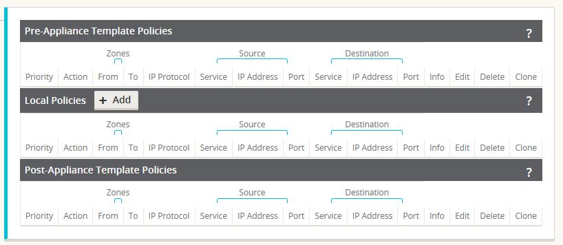
Pre-Appliance Template Policies are applied before any local site policies. Local site policies are applied next, followed by Post-Appliance Template Policies. The goal is to simplify the configuration process by allowing a user to apply global policies while still maintaining the flexibility to apply site-specific ones.
Note:
See the Filter Policy Evaluation Order below for specific information on how the system processes these policies.Filter Policy Evaluation Order
- Pre-Templates – compiled policies from all template “PRE” sections.
- Pre-Global – compiled policies from Global “PRE” section.
- Local – appliance-level policies.
- Local Auto Generated – automatically local generated policies.
- Post-Templates – compiled policies from all template “POST” sections.
- Post-Global – compiled policies from Global “POST” section.
Policy definitions - Global and Local (site)
The user will configure Pre-Appliance and Post-Appliance Template Policies at a global level. Local policies are applied at the site level of an appliance.
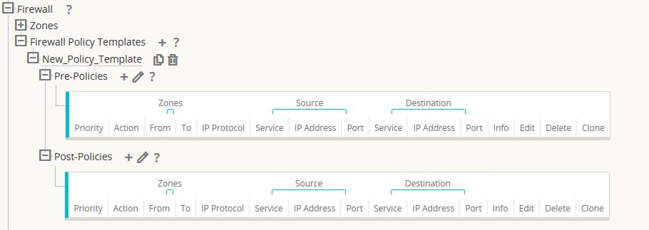
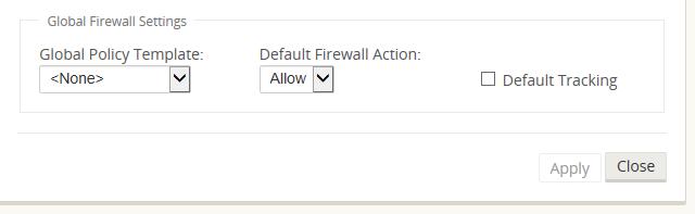
The above figure shows the policy template that would apply to the APN globally. To apply a template to all sites in the APN, navigate to APN Settings > Global Policy Template and select a specific policy. At the site level, the user can add more policy templates, as well as create site specific policies.
The specific configurable attributes for a policy are displayed in Figure 8. These are the same for all policies.
Note:
Ports configured for Oracle SD-WAN Reliable Protocol (UDP 2156, or a user-defined TRP port) are automatically permitted to prevent user-configurable polices from blocking a Conduit from establishing.
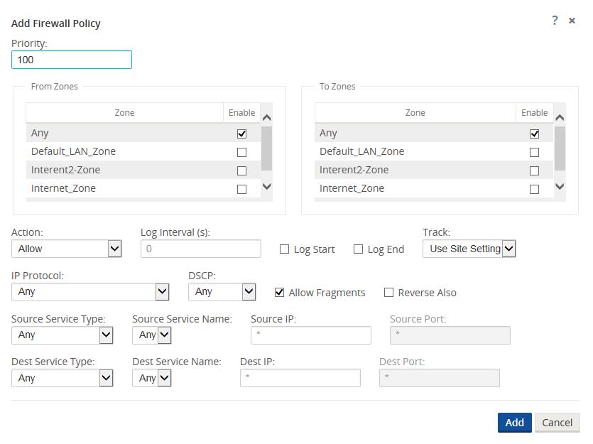
Policy Attributes
- Priority – order the policy will be applied within all the defined policies. Lower priority policies are applied before higher priority polices.
- Zone – flows have a source zone and destination zone.
- From Zone – source zone for the policy.
- To Zone – destination zone for a policy.
- Action – action to perform on a matched flow.
- Allow – permit the flow through the Firewall.
- Drop – deny the flow through the firewall by dropping the packets.
- Reject – deny the flow through the firewall and send a protocol specific response. TCP will send a reset, ICMP will send a redirect.
- Count and Continue – count the number of packets and bytes for this flow, then continue down the policy list.
- Log Interval – time in seconds between logging the number of packets matching the policy to a syslog server.
- Log Start – selected when a log file is created for new flow.
- Log End – log the data for a flow when the flow is deleted.
- Note: The default Log Interval value of 0 means no logging.
- Track – allows the firewall to track the state of a flow and display this information in the Monitor > Firewall > Connections table. If the flow is not tracked, the state will show NOT_TRACKED. See the table for the state tracking based on protocol below. Use the setting defined at the site level under Firewall > Settings > Advanced > Default Tracking.
- No Track – flow state is not enabled.
- Track – displays the current state of the flow (which matched this policy).
- IP Protocol – define an IP protocol. Options include ANY, TCP, UDP or ICMP.
- DSCP – allow the user to match on a DSCP tag setting.
- Allow Fragments – allow IP fragments that match this filter policy.
- Note: The firewall does not reassemble fragmented frames.
- Source Service Type – in reference to a Oracle SD-WAN service – Local (to the appliance), Conduit, Intranet, IPhost, or Internet are examples of Service Types.
- IPhost Option - This is a new service type for the Firewall and is used for packets that are generated by the Oracle SD-WAN application. For example, running a ping from the Web UI of the Oracle SD-WAN results in a packet sourced from a Oracle SD-WAN Virtual IP address. Creating a policy for this IP address would require the user to select the IPhost option.
- Note: Please refer to the Dynamic NAT – LAN to Untrusted Internet use case as an example.
- Source Service Name – name of a service tied to the service type. For example, if Conduit is selected for Source Service type, this would be the name of the specific Conduit. This is not always required and depends on the service type selected.
- Source IP address – typical IP address and subnet mask the filter will use to match.
- Source Port – source port the specific application will use.
-
Destination Service
Type - in reference to a
Oracle SD-WAN service –
Local (to the appliance), Conduit, Intranet, IPhost, or Internet are examples
of service types.
Note:
See above for definition of IPhost service type. - Destination Service Name - name of a service tied to the service type. This is not always required and depends on the service type selected.
- Destination IP Address - typical IP address and subnet mask the filter will use to match.
- Destination Port – destination port the specific application will use (i.e. HTTP destination port 80 for the TCP protocol).
- The track option provides much more detail about a flow. The state information tracked in the state tables is included below.
State Table for The Track Option
There are only a few states that are consistent:
- INIT: connection created, but the initial packet was invalid.
- O_DENIED: packets that created the connection are denied by a filter policy.
- R_DENIED: packets from the responder are denied by a filter policy.
- NOT_TRACKED: the connection is not statefully tracked but is otherwise allowed.
- CLOSED: the connection has timed out or otherwise been closed by the protocol.
- DELETED: the connection is
in the process of being removed.
- The DELETED state will almost never be seen.
All other states are protocol specific and require stateful tracking be enabled.
TCP can report the following states:
- SYN_SENT: first TCP SYN message seen.
- SYN_SENT2: SYN message seen in both directions, no SYN+ACK (AKA simultaneous open).
- SYN_ACK_RDVD: SYN+ACK received.
- ESTABLISHED: second ACK received, connection is fully established.
- FIN_WAIT: first FIN message seen.
- CLOSE_WAIT: FIN message seen in both directions.
- TIME_WAIT: last ACK seen in both directions. Connection is now closed waiting for reopen.
All other IP protocols (notably ICMP and UDP) have the following states:
- NEW: packets seen in one direction.
- ESTABLISHED: packets seen in both directions.
Network Address Translation (NAT)
The Oracle SD-WAN firewall allows the user to configure static NAT and dynamic NAT for different use cases. The following configurations are supported for NAT:
- Static one-to-one NAT
- Dynamic NAT (PAT- Port Address Translation)
- Dynamic NAT with Port Forwarding rules
Note:
At this time, the NAT capability can only be configured at the site level; there is no global configuration (templates) for NAT. All NAT policies are defined from a Source-NAT (SNAT) translation perspective. Corresponding Destination-NAT (DNAT) rules are created automatically for the user.Basic configuration of each type will be defined below so the user has an idea of what is required to enable a static or dynamic NAT capability. Specific examples of the use cases for NAT are provided later in this document.
Static NAT Configuration Options
Static NAT allows the user to configure one-to-one NAT, where an inside IP address will match a public IP address. The configuration options are shown in Figure 9. The user must also define the filter policies to allow traffic back in for the static NAT configuration.
Note:
Beginning in APN 7.2 P4, users have the option to enable the “Allow Return Flow” option to allow inbound connections as well as outbound connections without defining a second filter policy. Additional policies may still be required in some scenarios.
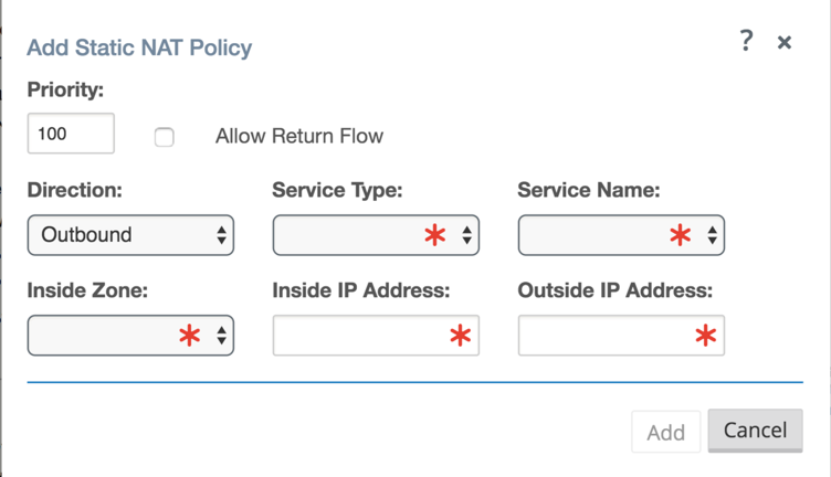
Figure 9
- Priority - the order the policy will be applied within all the defined policies. Lower priority policies are applied before higher priority polices.
- Direction – the direction, from the perspective of the virtual interface or service, that the translation will operate.
- Outbound – the destination address for a packet will be translated for packets received on the service. The source address will be translated for packets transmitted on the service. Example: LAN service to Internet service – for packets outbound, (LAN to Internet) the source IP address is translated. For packets inbound or received (Internet to LAN) the destination IP address are translated.
- Inbound - the source address for a packet will be translated for packets received on the service. The destination address will be translated for packets transmitted on the service. Example:Internet service to LAN service – For packets received on the Internet service, the source IP address is translated. For packets transmitted on the Internet service, the destination IP address is translated.
- Service Type – in reference to a Oracle SD-WAN service. For static NAT, these include Local (to the appliance), Intranet, and Internet.
- Service Name – specific service name that corresponds to the defined Service Type above.
- Inside Zone – one of the existing inside zones configured on the appliance.
- Inside IP address – source IP address and mask of the direction selected above.
- Outside IP address – the outside IP address and mask of packets that are translated to.
Dynamic NAT Configuration Options
Dynamic NAT is used when the user would want to forward traffic from a LAN segment to the Internet on an untrusted port. In this case, the user would configure the NAT in an outbound direction, as well as make sure the corresponding filter policies are defined to allow traffic back in. By default, once the dynamic NAT has been configured the system will add in two filter policies. These policies will:
- allow Any IPhost route, Any zone, Any source and destination.
- drop all other traffic from the source zone to the destination zone (zone specific).
Figure 10 provides the configuration options for the dynamic NAT configuration.
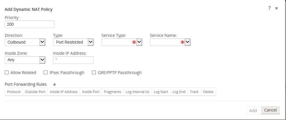
Figure 10
- Priority – the order the policy will be applied within all the defined policies. Lower priority policies are applied before higher priority polices.
- Direction – the direction from the virtual interface or service perspective the translation will operate.
- Outbound – the destination address for a packet will be translated for packets received on the service. The source address will be translated for packets transmitted on the service. Example: LAN service to Internet service – for packets outbound, (LAN to Internet) the source IP address is translated. For packets inbound or received (Internet to LAN) the destination IP address are translated.
- Inbound - the source address for a packet will be translated for packets received on the service. The destination address will be translated for packets transmitted on the service. Example:Internet service to LAN service – for packets received on the Internet service the source IP address is translated. For packets transmitted on the Internet service, the destination IP address is translated.
- Type – the type of dynamic NAT to perform.
- Port-Restrictive - Port-Restricted NAT is what most consumer grade gateway routers use. Inbound connections are generally disallowed unless a port is specifically forwarded to an inside address. Outbound connections allow return traffic from the same remote IP and port (this is known as endpoint independent mapping). This requirement limits a Port-Restricted NAT firewall to 65535 simultaneous sessions, but facilitates an often used internet technology known as hole punching.
- Symmetric – Symmetric NAT is sometimes known as enterprise NAT because it allows for a much larger NAT space and enhances security by making translations less predictable. Inbound connections are generally disallowed unless a port is specifically forwarded to an inside address. Outbound connections allow return traffic from the same remote IP and port. Connections from the same inside IP and port need to map to the same outside IP and port (this is known as endpoint dependent mapping). This mode explicitly prevents hole punching.
- Service Type – in reference to a Oracle SD-WAN service. For static NAT these include Local (to the appliance), Intranet, Internet.
- Service Name – the specific service name that corresponds to the defined Service Type above.
- Inside Zone – select the inside zone for the packets that require NAT.
- Inside IP address - define an IP host address or a subnet based on traffic that requires NAT. This should be an IP address that resides in the Inside Zone.
- Allow Related – allow traffic related to the flow matching the rule. For example, ICMP redirection related to the specific flow that matched the policy, if there was some type of error related to the flow.
- IPsec Passthrough – allow IPsec traffic to passthrough unchanged.
- GRE/PPTP Passthrough – allow GRE or IPsec to passthrough unchanged.
Dynamic NAT with Port Forwarding Configuration Options
Dynamic NAT with port forwarding allows the user to port forward specific traffic to a defined IP address. This is typically used for inside hosts like web servers. Once the dynamic NAT is configured the user would define the port forwarding policy. From the example in Figure 11, we can see that dynamic NAT is configured for a specific IP host address. The NAT example will map an inside IP host to an outside IP host. Port forwarding can then be configured which will define a specific inside and outside port mapped to an inside IP address. In this example, HTTP port 80 is defined for port forwarding.
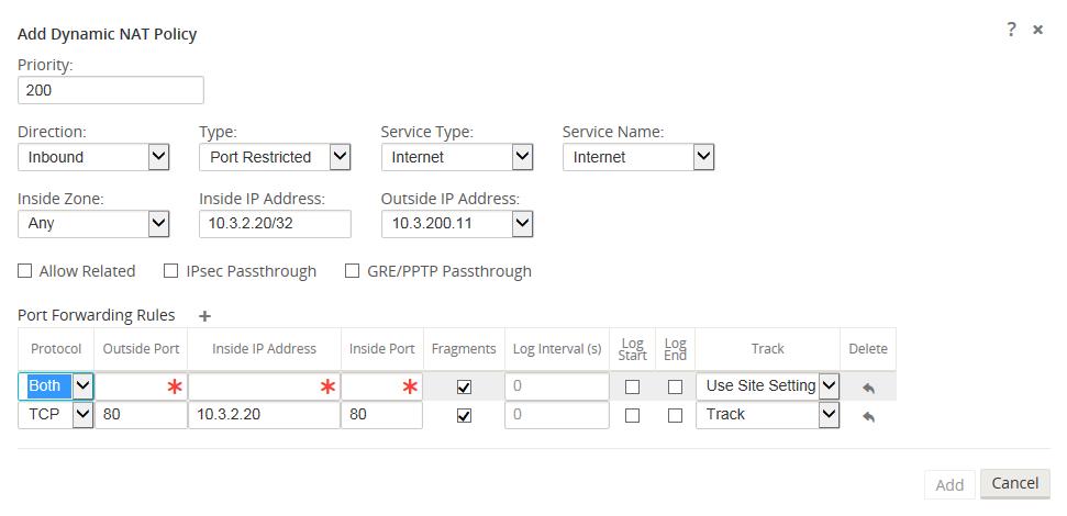
- Protocol – TCP, UDP, or both.
- Outside Port – outside port the user will port forward into the inside address.
- Inside IP address – inside address to forward matching packets.
- Inside Port – map the packet to the same, or a different, inside port.
- Fragments – allow the forwarding of fragmented packets.
- Log Interval – time in second between logging the number of packets matching the policy to a syslog server.
- Log Start – selected when a log file is created for new flow.
-
Log End – log
the data for a flow when the flow is deleted.
Note:
The default Log Interval value of 0 means no logging. - Track – allows the firewall to track the state of a flow and display this information in the Monitor > Firewall > Connections table. If the flow is not tracked, the state will show NOT_TRACKED. See the table for the state tracking based on protocol below. Use the setting defined at the site level under Firewall > Settings > Advanced > Default Tracking.
- No Track – flow state is not enabled.
- Track – displays the current state of the flow (which matched this policy).
Filter Policies
When filtering using zones, traffic that is using a Conduit route that was manually configured in the Routes section does not know the To Zone until the traffic arrives at the remote site. Filter Policies for this traffic must be configured at the remote site.
When filtering using zones, traffic from a private VIP may only be filtered at the local site using the zone for the private VIP. Similarly, if the source IP address for a packet is translated using NAT, the original Inside Zone can only be filtered locally. Remote appliances must use the Outside Zone.
Static & Dynamic NAT Policies
NAT translations are not permitted if the Inside and Outside Zones are the same.
While both inbound and outbound translations can be configured simultaneously for a service, only the first to match will be used. Multiple translations may occur if a rule exists on the service a packet is received on and the service a packet is sent on.
Note: Dynamic NAT translations allow all reciprocal traffic for sessions initiated from the inside network. To filter these connections, add filter policies for the outbound traffic. Static NAT translations allow reciprocal traffic for sessions initiated from inside the network only on policies with the “Allow Return Flow” option enabled.
Firewall Use Case Examples
Dynamic NAT – LAN to Untrusted Internet
In this example, the firewall will allow the local users Internet access at a Client site. The Internet access will utilize the firewall to NAT the traffic to the Internet while providing policies to limit or deny any traffic that did not originate from the inside LAN segment. If configured, the Oracle SD-WAN will also now provision the Internet usages on this WAN Link. In the past, this was not possible because an untrusted port would only allow ICMP, ARP, and TRP packets, while all other traffic was blocked. A diagram of the Client site is included in Figure 12.
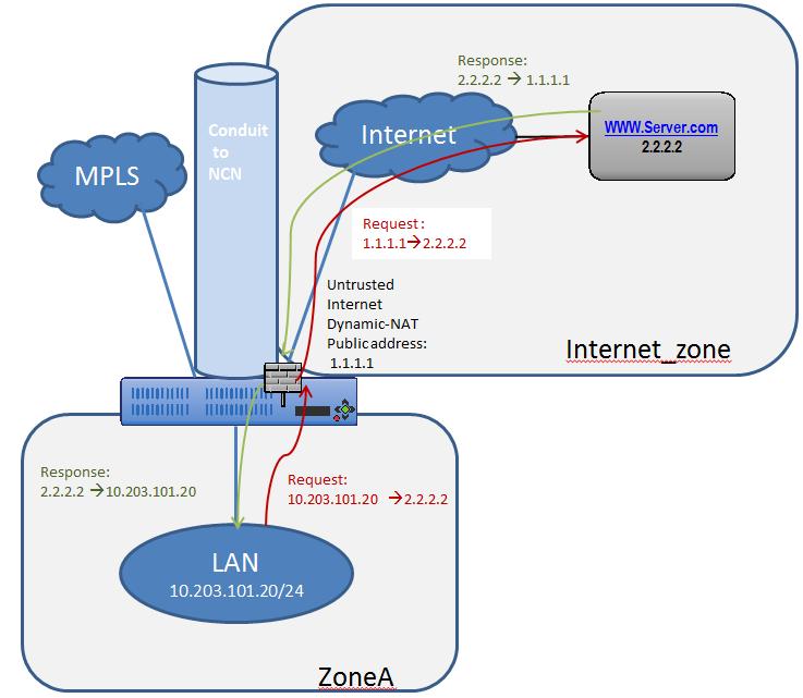
Figure 12
The configuration process to enable this capability is as follows, assuming the Oracle SD-WAN Client site is currently up and operational.
- Add the Internet service to the site.
- Assign it to the WAN Link (even though the WAN Link is untrusted).
- Define the dynamic NAT policies (PAT rule).
- The system will add policies to allow traffic in and out for this NAT statement.
- Save the configuration and
Export it to
Change Management.
Steps 1 & 2 - Adding the Internet service and assigning it to a WAN Link.
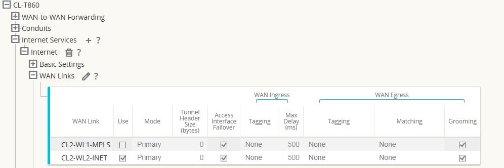
Figure 13
The Internet service was added to the site with service name “Internet”. Once added, the service was applied to WAN Link “CL2-WL2-INET”. By default, the bandwidth allocated to the new Internet service is 1000 shares. If more bandwidth is required, the user should review the Provisioning section in the Configuration Editor under Provisioning > [Site Name] > WAN Links > CL2-WL2-INET > Services > Internet.
Once the Internet service has been added and assigned to a WAN Link, the user can then configure the dynamic NAT function. Since this use case only requires dynamic NAT, there are no global policies to apply. All required policies can be added locally to the site. Figure 14 provides a screen capture of how the user should configure the dynamic NAT capability.
Navigate to Connections > [Site Name] > Firewall > Dynamic NAT Policies > Add.
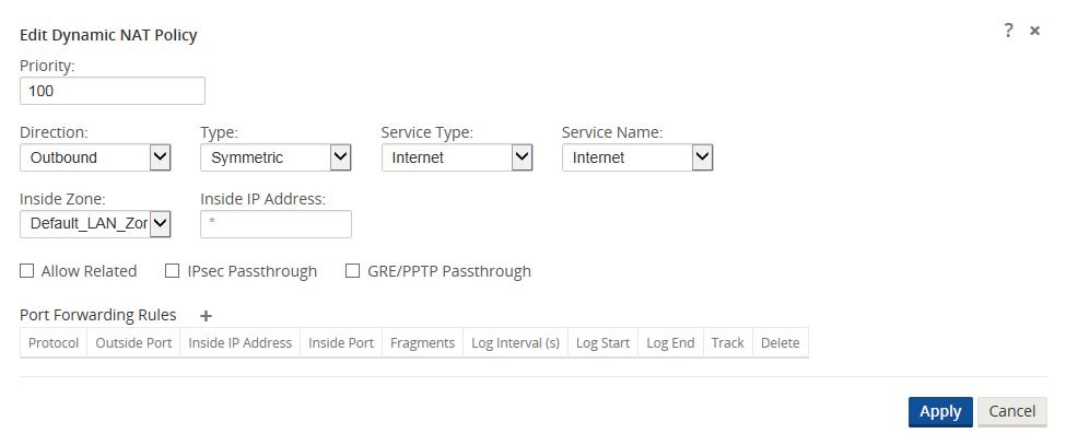
Figure 14
Define the dynamic NAT policies (PAT rule):
- Direction: Outbound
- Type: Symmetric (Firewall can change the source port)
- Service Type: Internet
- Service Name: Internet
- Inside Zone: Default_LAN_Zone
- Inside IP address: * (default)
- Outside zone: Internet_Zone (because of defined service type this is known)
The completed Dynamic NAT Policy will be displayed as follows:

Figure 15
In addition to the NAT policy, the system will add two default policies. The first policy allows traffic outbound from a Oracle SD-WAN Virtual IP address (IP Host) and the NAT process. The second rule will deny all other inbound traffic from the Internet_Zone . System added rules are marked with a priority of (auto) and the user can add policies with a higher priority if necessary.
Note: The rule that allows this traffic outbound is the default rule defined at the global level to Allow all firewall traffic. If the default policy is set to Drop, the user must add a more specific policy that allows all LAN traffic outbound to the Internet.
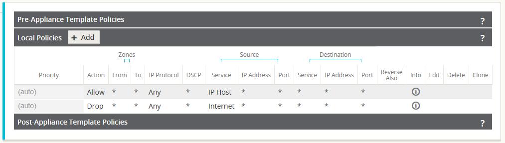
Figure 16
Once the configuration is complete, the user will Export the configuration to Change Management to apply the changes.
Policies Between Zones
In this example, the firewall will allow traffic only to the same zone as it originated (Zone_A > Zone_A). Traffic destined to a different zone will be blocked (Zone_A > Zone_B). The filtering affects both APN (WAN) as well as appliance-local traffic (L3 interface to L3 interface). A topology diagram is included in Figure 17.
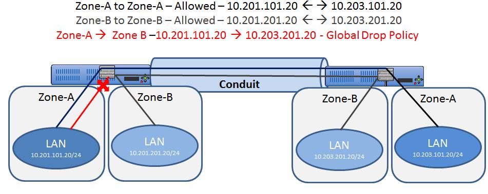
Figure 17
The configuration process to enable this capability is as follows, assuming the Oracle SD-WAN Client site is currently up and operational.
- Create and assign zones (Zone_A & Zone_B) to interfaces.
- Create filter-policy
template to:
- Permit Zone_A > Zone_A traffic.
- Permit Zone_B > Zone_B traffic.
- Assign filter-policy template to sites.
- Configure default global behavior as drop.
- Save the configuration and Export to Change Management.
Note: Step 4 may also be done locally if required.
Step 1- Create and assign zones (Zone_A & Zone_B) to interfaces.
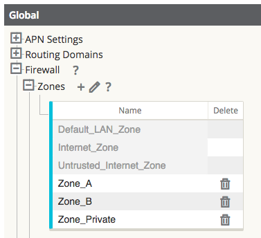
Figure 18
Figure 18 shows how the zone is added at the global level. Once the zone is created, it must be assigned to a logical interface within the Oracle SD-WAN Appliance.
Figure 19 provides an example of how the user assigns the zone to a VNI. Under Site > [Site Name] > Interface Groups > Virtual Interface the user can select an interface or interface pair, then assign a zone.
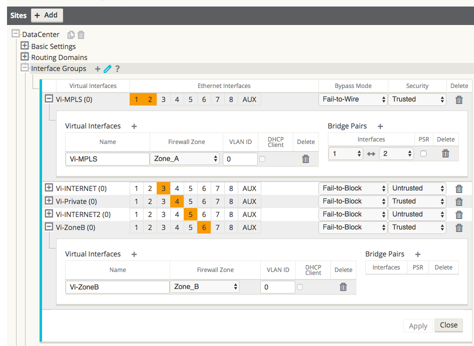
Figure 19
Step 2 - Create a filter-policy template to:
- Permit Zone_A > Zone_A traffic.
- Permit Zone_B > Zone_B traffic.
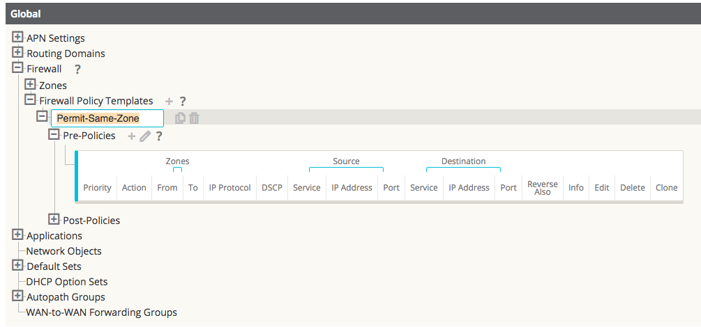
Figure 20
Note:
This template can then be applied to all appliances in the APN, if required.Figure 21 shows the user how to configure Zone_A (source) and Zone B (destination). In this example, all other policy options are set to the Any or the * option, with more selective security options available if required.
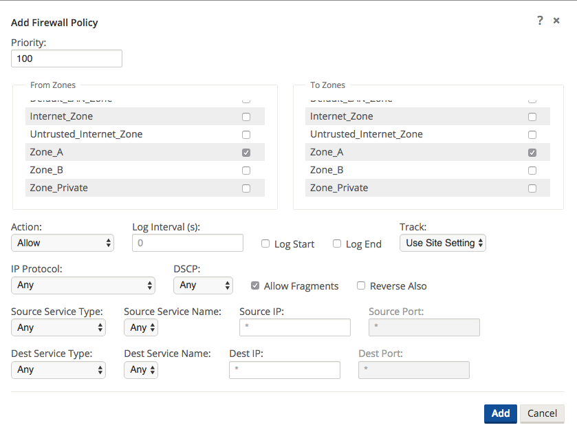
Figure 21
Repeat the process for Zone_B policies.
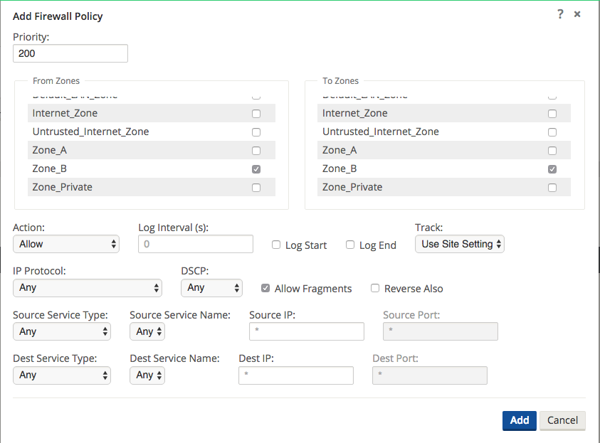
Figure 22
Once the policies are created to allow zone to zone traffic, they will be displayed as seen below.
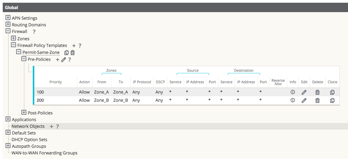
Figure 23
Step 3 - Assign the filter-policy template to sites.
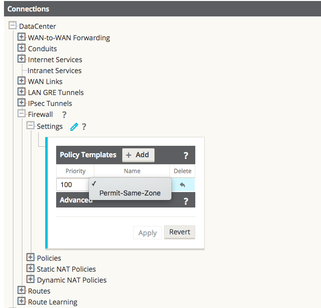
Figure 24
Assigning a Pre-Appliance policy to a site is done under Connections > [Site Name] > Firewall > Settings > Policy Template > Add.
Example of the applied Policy Template for NCN and Client Sites:
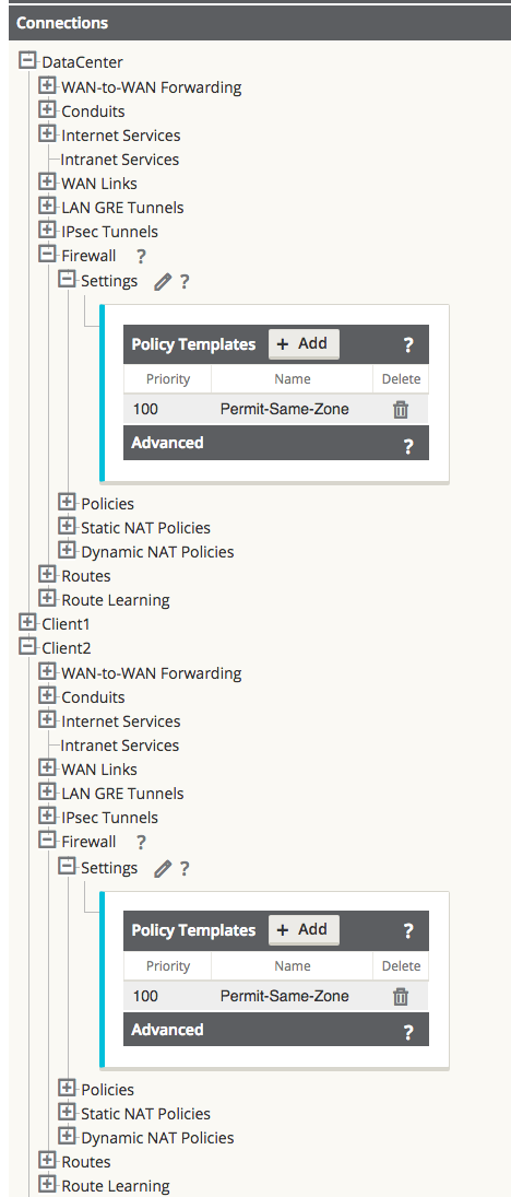
Figure 25
Step 4 - Configure the default global behavior to Drop.
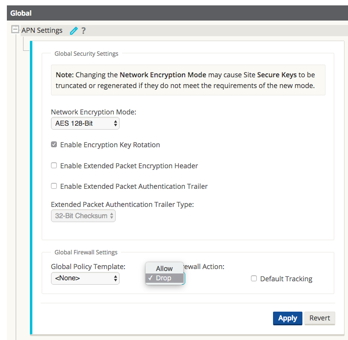
Figure 26
In this example, once the zone to zone policies are defined, the user elects to deny all other traffic. This configuration option is found under the Global > APN Settings > Firewall Action > Drop.
Note:
Use this option with caution, as all other traffic will now be dropped.Once the configuration is complete in the Editor, the user will Export the configuration to Change Management to apply the changes.
LAN to Conduit Zone to Zone – Block/Allow Specific Traffic Types
In this example, the firewall will deny a specific sub-set of traffic (TCP with destination port 23) globally. The filtering affects both APN (WAN) as well as appliance-local traffic (L3 interface to L3 interface). A topology diagram is included in Figure 27.
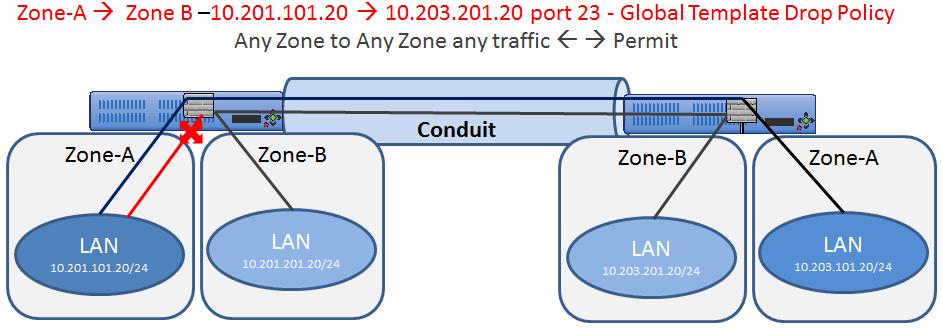
Figure 27
The configuration process to enable this capability is as follows, assuming the Oracle SD-WAN Client site is currently up and operational.
- Create filter-policy template to deny TCP with destination port 23 traffic.
- Assign filter-policy template to sites.
- Save the configuration and Export to Change Management.
Step 1 - Create filter-policy template to deny TCP with destination port 23 traffic.
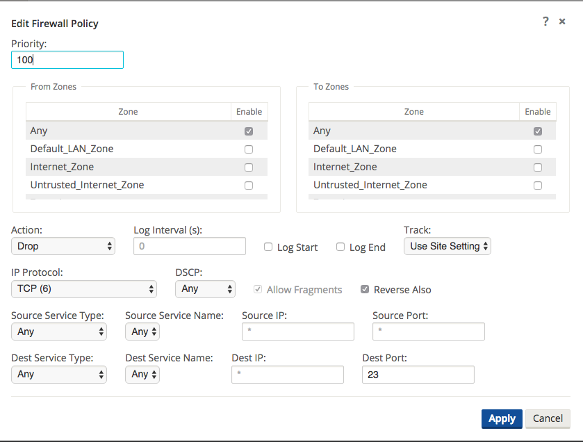
Figure 28
In Figure 28, the user creates a policy to Drop TCP traffic with destination port 23 with a source or destination of any IP address. The user can also select the Track option for such flows if complete TCP state monitoring is desired.
The user also has the option to make this policy Pre-Appliance, Post-Appliance, or site specific. The screen shot below displays that the user has chosen to make this policy a Global Pre-Appliance Policy.
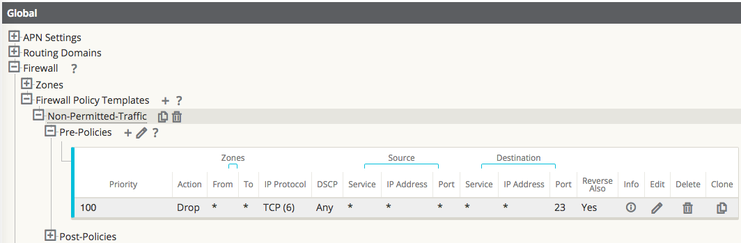
Figure 29
Step 2 - Assign the filter-policy template to sites.
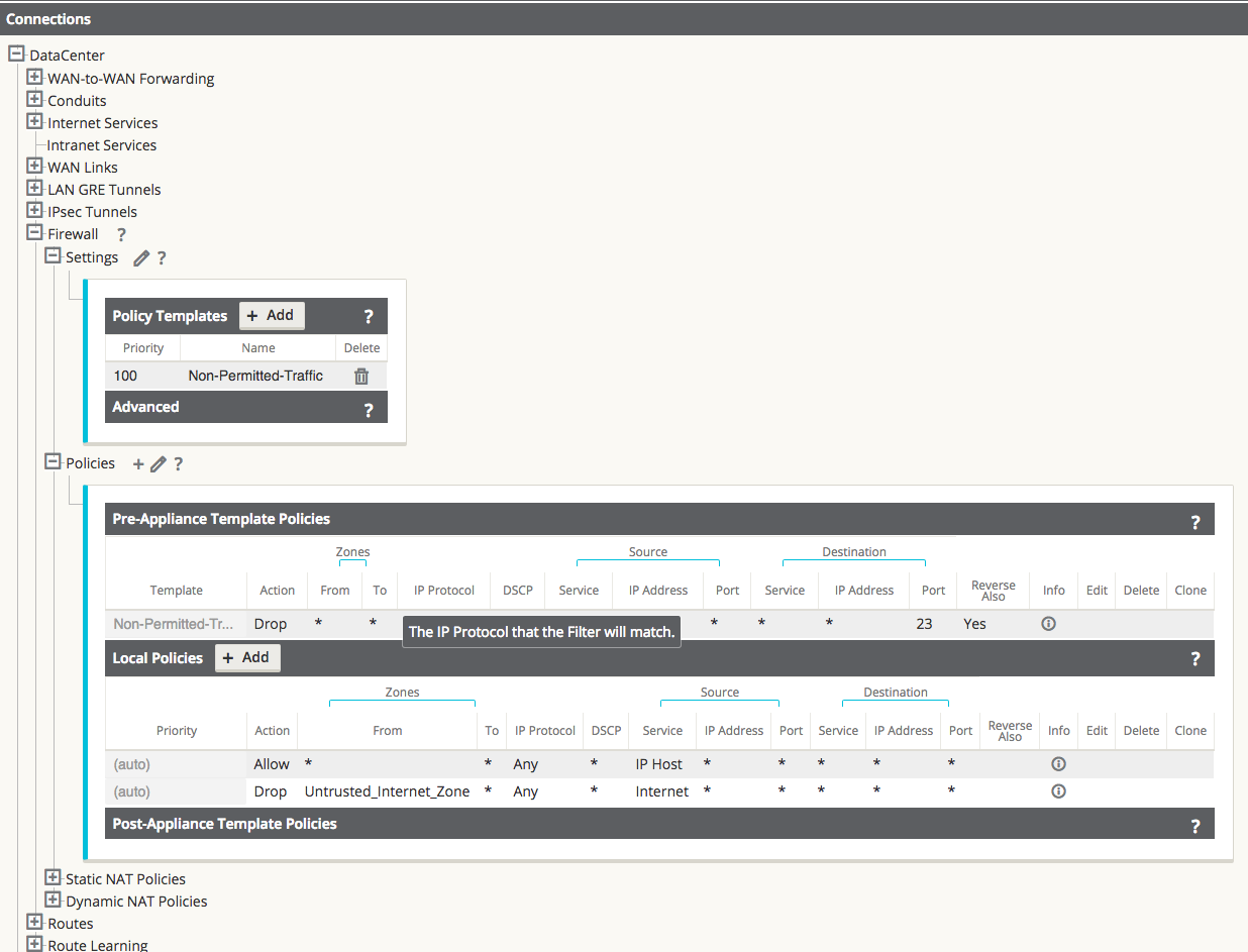
Figure 30
The template can be assigned to a specific site under Connections > [Site Name] > Firewall > Settings.
Save the configuration and Export to Change Management.
Internet (untrusted) Port Forwarding – DMZ
In this example, the firewall will port forward specific traffic arriving on an outside/untrusted Internet VIP (TCP/8080) to an inside/LAN host (TCP/80). A topology diagram is included in Figure 31.
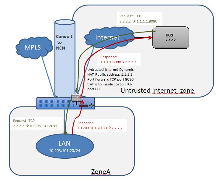
Figure 31
The configuration process to enable this capability is as follows, assuming the Oracle SD-WAN Client site is currently up and operational.
- Define the dynamic NAT policies (PAT rule).
- The system will add policies to allow traffic in and out for this NAT statement.
- Save the configuration and Export to Change Management.
Step 1 - Define the dynamic NAT policies (PAT rule) under Connections > [Site Name] > Firewall > Dynamic NAT Policies.
- Direction: Outbound
- Type: Port-Restricted (Firewall can change the source port)
- Service: Internet
- Inside Zone:* (default)
- Inside IP Address: * (default)
- Outside Zone: Untrusted_Internet_Zone
- Outside IP Address: blank
- Port Forwards: 1
- Outside: TCP/8080, Inside: 10.203.101.20 TCP/80
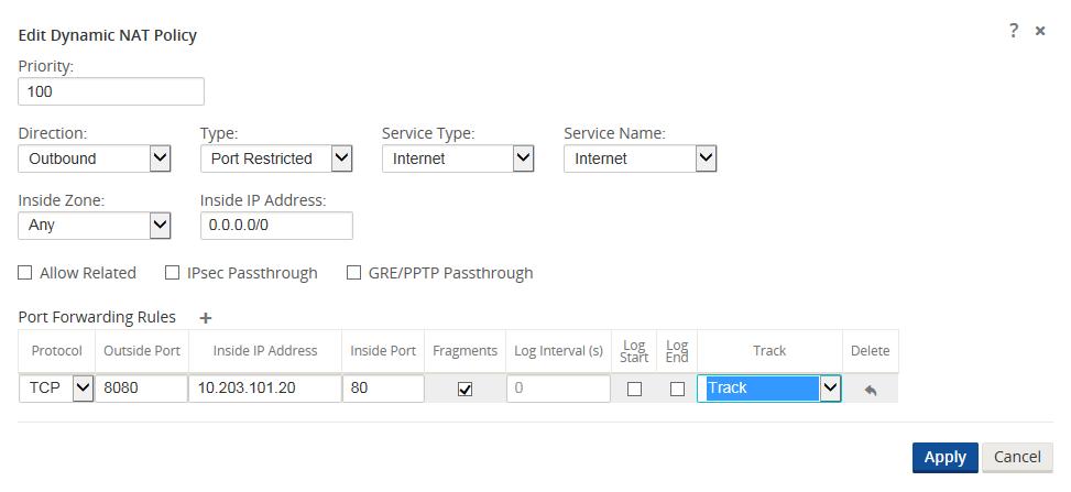
Figure 32
When configuring Port Forwarding, the user must define the dynamic NAT (PAT) prior to enabling the specific Port Forwarding Rules. Figure 32 displays that dynamic NAT is enabled to the Internet Service Type, then the Port Forwarding Rule may be created. The requirements in this example are to port forward TCP port 8080 traffic inbound for host 10.203.10.20 on TCP port 80. The user will also Track the state of this connection.
Step 2 - The system will add policies to allow traffic in and out for this dynamic NAT statement and the Port Forwarding Policy and should be verified by the end user under the Policies section.
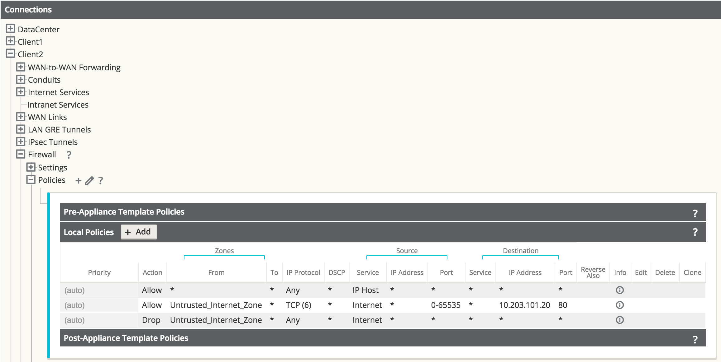
Figure 33
Figure 33 shows the rules automatically generated by the system. These rules will allow dynamic NAT to the Internet from an inside host, as well as to port forward any traffic from the Internet to that specific host on TCP port 80. This simplifies the configuration process for the end user.
Save the configuration and Export to Change Management.
Static One-to-One NAT - Internet to LAN/DMZ Host
In this example, the firewall will use static NAT for traffic from an outside host to a host residing on the LAN or DMZ segment. This is a one-to-one NAT so all traffic for the 1.1.1.1 destination address will NAT to the inside address of 10.203.101.20. The reverse NAT rule for traffic outbound is implied. All IP protocols (TCP, UDP, GRE etc.) are forwarded.
Note: The mask used in this example allows users to map to a specific inside host address.
A topology diagram is included in Figure 34.
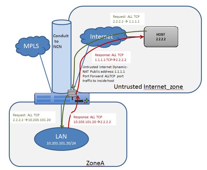
Figure 34
The configuration process to enable this capability is as follows, assuming the Oracle SD-WAN Client site is currently up and operational.
- Define the static NAT policies (one-to-one rule).
- Create filter policy to permit Untrusted_Internet_Zone traffic inbound.
- Save the configuration and Export to Change Management.
Step 1 - Define the static NAT policies (one-to-one rule):
- Direction: Outbound
- Service: Internet
- Inside Zone: Zone_A
- Inside IP Address: 10.203.101.20/32
- Outside Zone: Untrusted_Internet_Zone
- Outside IP Address: 1.1.1.1/32
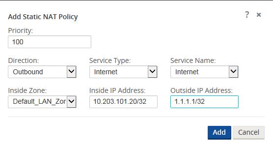
Figure 35
Users will navigate to Connections > [Site Name] > Firewall > Static NAT Policies to add a new policy. The figure above shows the options available to the user. Enabling the static NAT does not apply any automatic policies so the user must configure specific policies to allow or drop traffic. In the above policy, outside IP address 1.1.1.1 maps to inside IP address 10.203.101.20.
Step 2 - Create the filter policy to permit Untrusted_Internet_Zone traffic inbound.
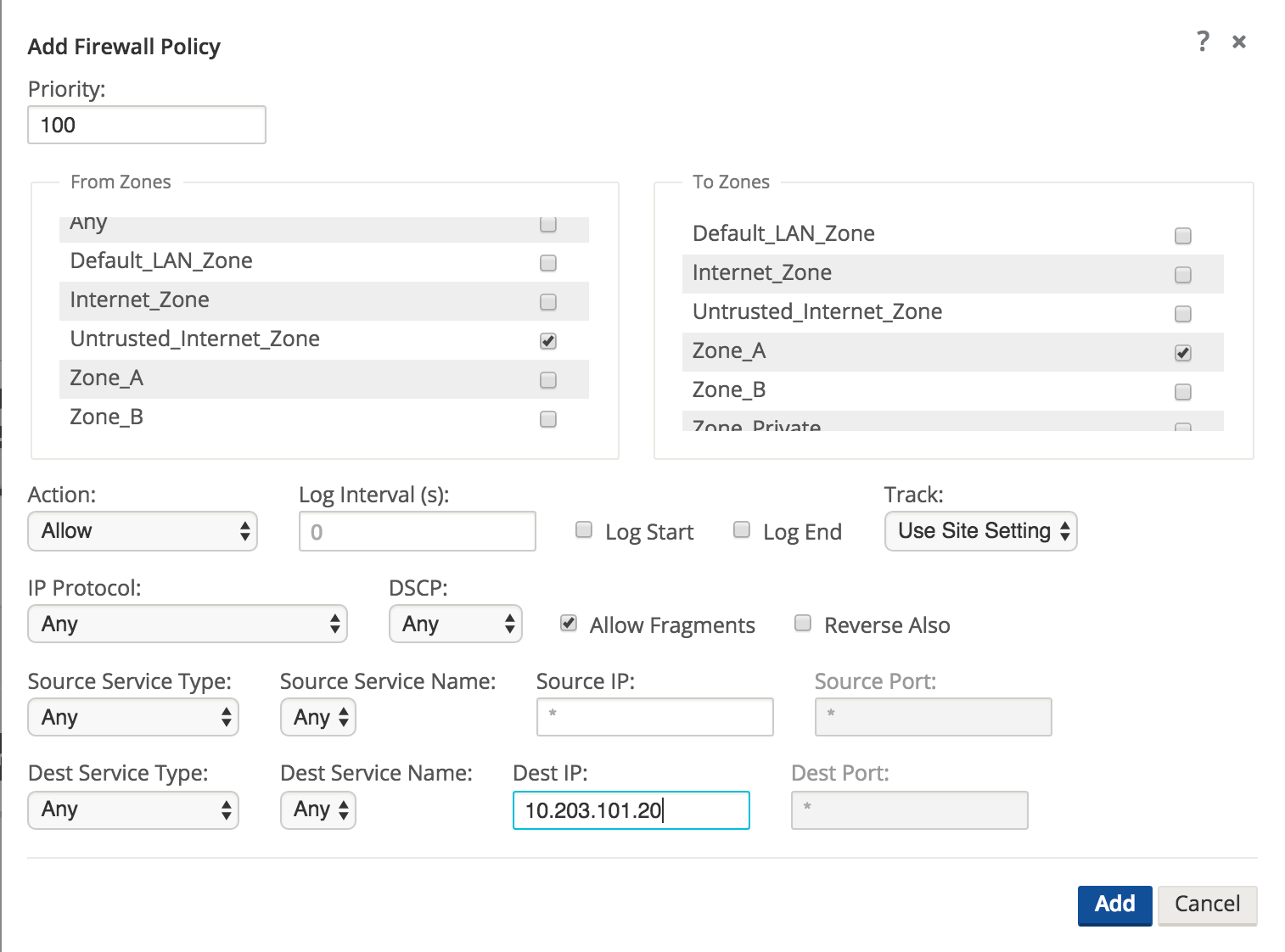
Figure 37
To configure traffic policies, the user must understand what traffic is going to be allowed or dropped. Figure 37 shows a sample policy allowing any traffic from the Untrusted_Internet_Zone (a pre-defined zone on the Oracle SD-WAN Appliance) to inside Zone_A (which is manually user-defined). The policy allows any IP protocol, with any source IP address and port through to the inside host address. The user may define more specific policies as required.
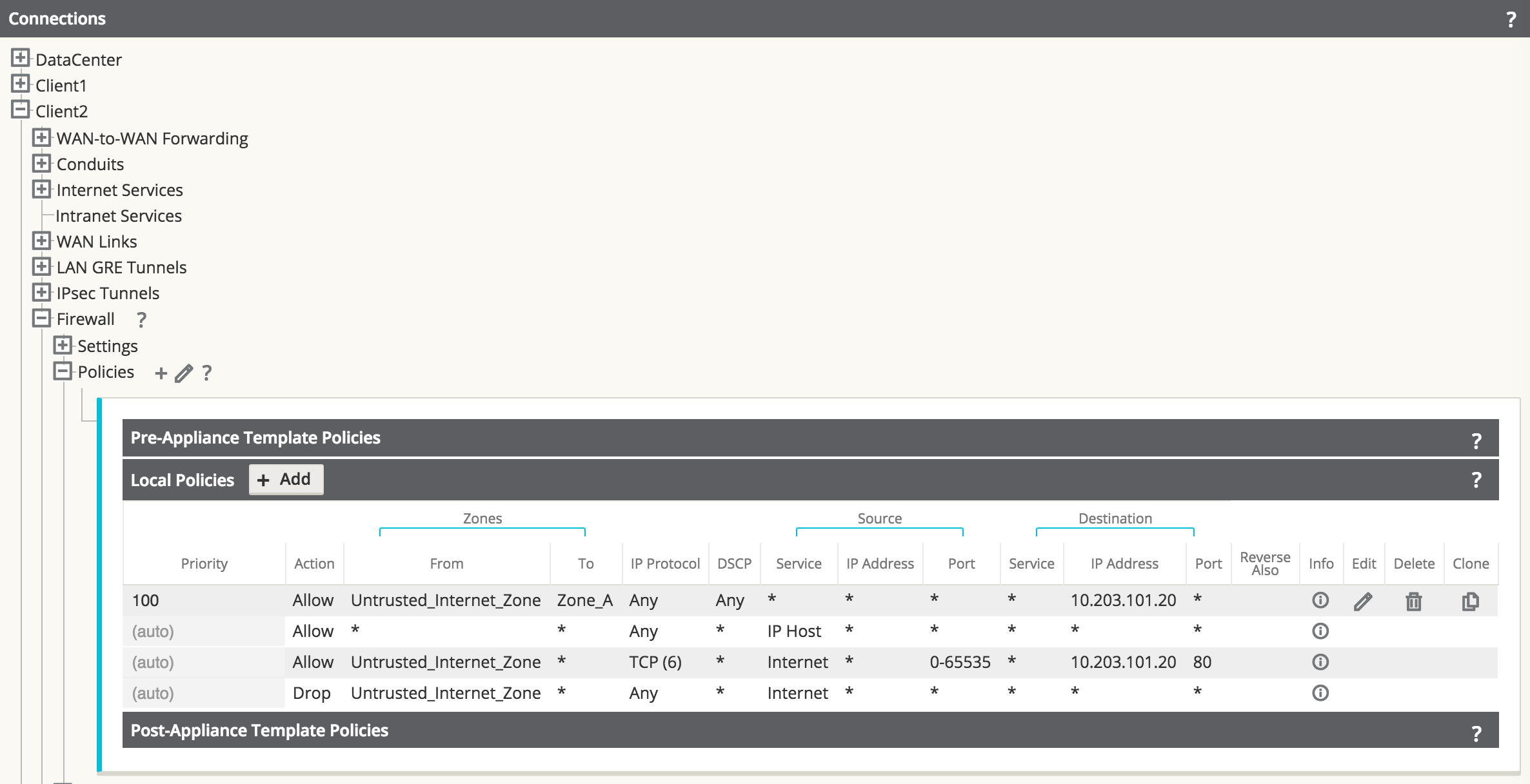
Figure 38
Once the policies are defined to allow the traffic, the user should expand the configuration out to review them and verify, as shown above.
Save the configuration and Export to Change Management.
Private LAN (VNI-NAT) into Conduit APN and Internet
In this example, the firewall will employ two separate NAT operations, an inbound static NAT and an outbound dynamic NAT (PAT). The reason for the inbound static NAT is the source network (192.168.0.0/24) is a non-unique network and exists at every network location; 192.168.0.0/24 will NAT to an APN-unique network to allow for overlap translation. The outbound dynamic NAT (PAT) is the standard for LAN to Internet traffic. A topology diagram is included in Figure 39.
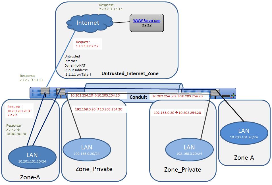
Figure 39
The configuration process to enable this capability is as follows, assuming the Oracle SD-WAN Client site is currently up and operational.
- Set Private Zone interfaces as Private under VIP configuration.
- Define the static NAT Policy (one-to-one) – Branch Office 1.
- Define the static NAT Policy (one-to-one) – Branch Office 2.
- Define the dynamic NAT Policy (PAT) – Both Offices.
- Save the configuration and Export to Change Management.
Step 1 - Set Private Zone interfaces as Private by selecting the checkbox under VIP configuration and define local subnet 192.168.0.0/24. This route will have local significance only and is not advertised within the APN routing table.
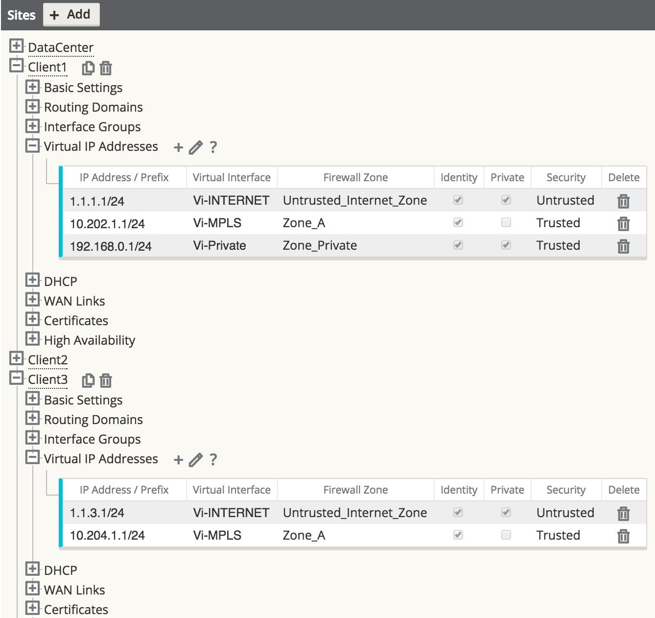
Figure 40
Step 2 - Define the static NAT Policy (one-to-one) – Branch Office 1.
- Direction: Inbound
- Service: Local
- Inside Zone: Zone_Private
- Inside IP Address: 192.168.0.0/24
- Outside Zone: Zone_A
- Outside IP Address: 10.202.254.0/24
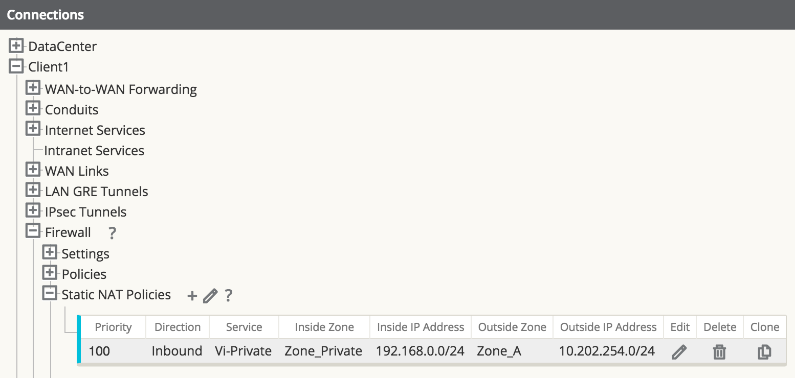
Figure 41
The user may add Static NAT Policies, but this will apply to the subnet. Host addresses within the subnet will match, for example, 192.168.0.20 will map to 10.202.254.20. The Service type selected is a local service called “Vi-Private” that corresponds to the private address space selected as Zone_Private. The above policy is an inbound statement stating that any LAN traffic from the private address space will NAT to the inside address space, and is then routed across the APN.
Repeat the process for Branch Office 2. Once Branch Office 2 is complete, the NAT for the private address space is complete. Next, the user will configure the dynamic NAT to the Internet.
Step 3 - Define the static NAT Policy (one-to-one) – Branch Office 2.
- Direction: Inbound
- Service: Local
- Inside Zone: Zone_Private
- Inside IP Address: 192.168.0.0/24
- Outside Zone: Zone_A
- Outside IP Address: 10.203.254.0/24
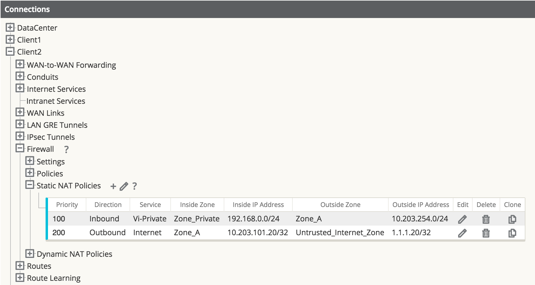
Figure 42
Step 4 - Define the dynamic NAT Policy (PAT) – Both Offices.
- Direction: Outbound
- Type: Port-Restricted (FW can change the source port)
- Service: Internet
- Inside Zone:* (default)
- Inside IP Address: * (default)
- Outside Zone: Untrusted_Internet_Zone
- Outside IP Address: blank
- Port Forwards: 0
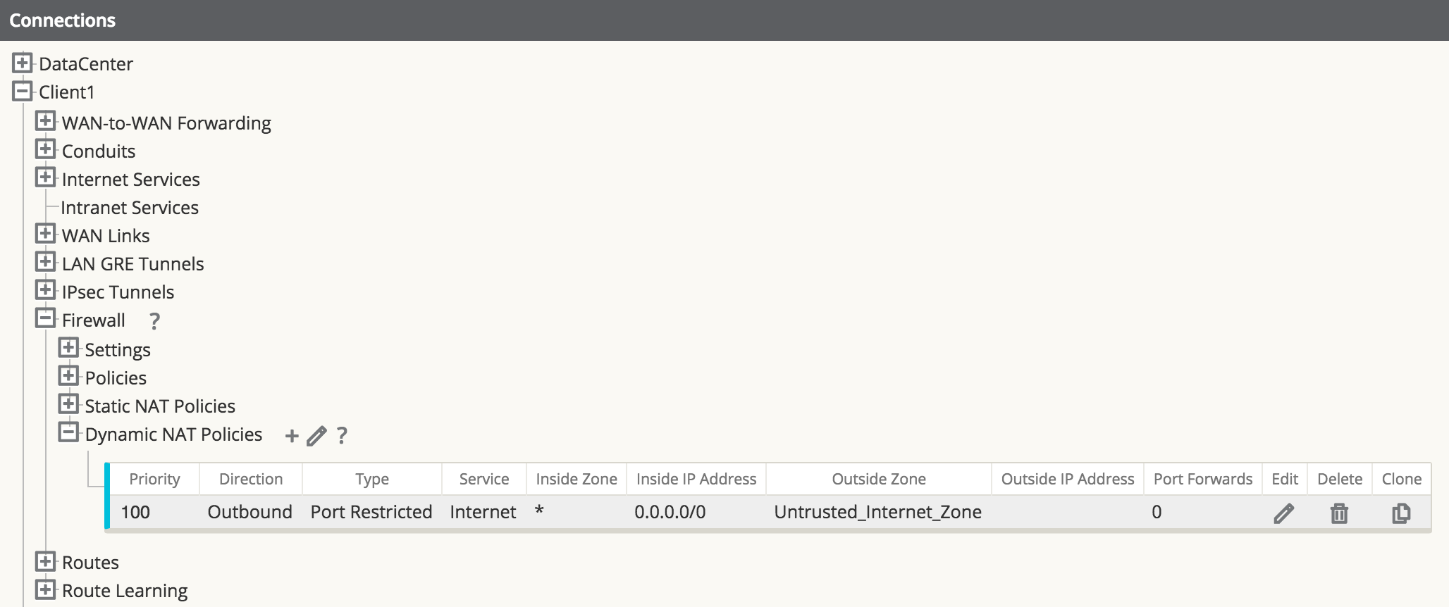
Figure 43
Note:
Figure 43 only represents one office, and does not show both.The final step is to configure the dynamic NAT for Internet access. This is accomplished by selecting the inside zone to be any (or *) zone and the outside zone to be the Untrusted_Internet_Zone, as was configured in the first example. Since the inside zone and IP address space are both set to any, all local users will NAT to the Internet, including the private address space which NATs to the local inside address space.
Save the configuration and Export to Change Management.
Firewall Configuration
In a
Oracle SD-WAN WAN, a WAN Path is a
logical, one-way, UDP encapsulated flow of data between two
Oracle SD-WAN Appliances and a
constituent part of a Conduit. Conduits use
Oracle SD-WAN Reliable Protocol (TRP) on
UDP Port 2156 by default, but the UDP Port number can be manually configured
for each Conduit.

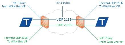
UDP Port Mapping and Forwarding
When a Oracle SD-WAN Appliance is installed behind a firewall or NAT device it is necessary to ensure the TRP traffic is permitted in each direction and mapped to the corresponding internal WAN Link Virtual IP Address (VIP).
Firewall Access Rules
Firewall vendors often employ associative object-based components to create service rules for access to the private network. These guidelines are listed below, however, consult your firewall vendor documentation for specific configuration instruction.
- Service Object—By default, TRP uses UDP 2156. If the port number is changed in the configuration, the service object should match.
- Host Object—The WAN Link VIP as it appears to the firewall from the private network.
- NAT Policy—Apply NAT to the outbound TRP traffic referencing the Service and Host Objects.
- Security Policy—Allow inbound TRP traffic from the remote Oracle SD-WAN Appliance. Depending on the firewall make and model this may be implicitly allowed through the NAT Policy.
| Objects and Policies | Properties |
| Service Object | UDP Port 2156 |
| Host Object | WAN Link VIP |
| NAT Policy | NAT Host and Service |
| Security Policy | Permit or Forward UDP 2156 to WAN Link VIP |
Troubleshooting
Incorrect firewall configuration may result in a DEAD Path in one or both directions. A Path is DEAD when no TRP packets are received for 1500ms or longer.
- Verify that the firewall configuration matches the configured WAN Link VIPs and UDP ports.
- Are TRP packets being received on the sending firewall from the LAN?
- Inspect packet flow on
the sending firewall:
- Are TRP packets using the expected NAT Policy and have the correct public IP Address?
- Are TRP packets forwarded from the correct public facing interface?
- 4. Inspect packet flow on
the receiving firewall:
- Are TRP packets arriving on the public facing interface?
- Are TRP packets forwarded to the LAN on the correct private facing interface?
- Inspect the packet flow
on the receiving
Oracle SD-WAN Appliance:
- Are TRP packets arriving on the associated WAN Link Interface Group?


