| Oracle® Communications OC-CNE Installation Guide Release 1.0 F16979-01 |
|

 Previous |
 Next |
Network Redundancy Mechanisms
Server Level Redundancy
Production Use-Case
Lab Use-Case
Enclosure Switch Redundancy
ToR Switch Redundancy
OAM Uplink Redundancy
Signaling Uplink Redundancy
OAM and Signaling Separation
This section is intended to cover the redundancy mechanisms used within the CNE Platform. With all links, BFD should be investigated as an optimal failure detection strategy.
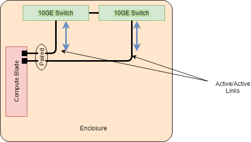
The blade server hardware will be configured with a base pair of 10GE NICs that map to Enclosure IO bays 1 and 2. IO bays 1 and 2 will be equipped with 10GE switches. The blade server OS configuration must pair the base pair of NICs in an active/active configuration.
Figure B-19 Blade Server NIC Pairing
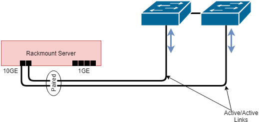
The rackmount servers (RMS) will be configured with a base quad 1GE NICs that will be mostly unused (except for switch management connections on the management server). The RMS will also be equipped with a 10GE Flex LOM (FLOM) card. The FLOM NIC ports will be connected to the ToR switches. The RMS OS configuration must pair the FLOM NIC ports in an active/active configuration.
Figure B-20 Rackmount Server NIC Pairing
The production environment will use LACP mode for active/active NIC pairing. This is so the NICs can form one logical interface, using a load-balancing algorithm involving a hash of source/dest MAC or IP pairs over the available links. For this to work, the upstream switches need to be "clustered" as a single logical switch. LACP mode will not work if the upstream switches are operating as independent switches (not sharing the same switching fabric). The current projected switches to be used in the solution are capable of a "clustering" technology, such as HP's IRF, and Cisco's vPC.
Some lab infrastructure will be able to support the production use-case. However, due to its dependence on switching technology, and the possibility that much of the lab will not have the dependent switch capabilities, the NIC pairing strategy will need to support an active/active mode that does not have dependence on switch clustering technologies (adaptive load balancing, round-robin), active/standby that does not have dependence on switch clustering technologies, or a simplex NIC configuration for non-redundant topologies.
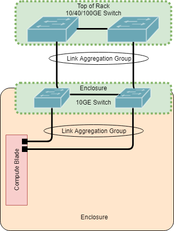
To support LACP mode of NIC teaming, the Enclosure switches will need to be clustered together as one logical switch. This will involve the switches to be connected together with the Enclosure's internal pathing between the switches. Below is an Enclosure switch interconnect table for reference.
Each blade server will form a 2x10GE Link Aggregation Group (LAG) to the upstream enclosure switches. Up to 16 blades will be communicating through these enclosure switches. Without specific projected data rates, the enclosure uplinks to the Top of Rack (ToR) switches will be sized to a 4x10GE LAG each. Thus, with the switches logically grouped together, an 8x10GE LAG will be formed to the ToR.
For simplicity's sake, the figure below depicts a single black line for each connection. This black line may represent one or more links between the devices. Consult the interconnect tables for what the connection actually represents.
Figure B-21 Logical Switch View
The ToR switch is intended to be deployed as a single logical unit, using a switch clustering technology. If the ToR switch does not support switch clustering, then, minimally, the switch must support Virtual Port channeling technology that allows the downlinks to both enclosure switches to be logically grouped into a common port channel. This is to simplify design, increase throughput, and shorten failover time in the event of a switch failure. Connections upstream to the customer network will be dependent on customer requirements. For the initial launch of CNE, the uplink requirement will vary depending on OAM or Signaling uplink requirements.
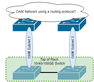
The OAM network uplinks are expected to use static routing in the first deployment of CNE for a targeted customer. This means that the first ToR switch will have a default route to a specific customer OAM router interface, while the other ToR switch has a default route to a different customer OAM router interface. If the ToR switches are clustered together as one logical switch, then this behavior should still work in certain failure scenarios, but more testing would be needed. For example, if the link to OAM subnet 1 were to go down, then the switch physical or virtual interface to OAM subnet 1 should go down, and thus be removed from the route table. If, however, the switch link doesn't go down, but the customer OAM router interface were to become unreachable, the static default route to OAM subnet 1 would still be active, as there is no intelligence at play to converge to a different default route. This is an area in need of further exploration and development.
Figure B-22 OAM Uplink View
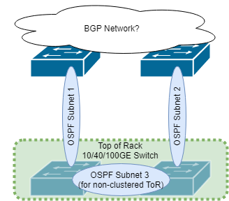
The signaling network uplinks are expected to use OSPF routing protocol with the customer switches to determine optimal and available route paths to customer signaling router interfaces. This implementation will require tuning with the customer network for optimal performance.
If the ToR switches are able to cluster together as one logical switch, then there is no need for an OSPF relationship between the ToR switches. In this case, they would share a common route table and have two possible routes out to the customer router interfaces. If, however, they do not cluster together as a single logical unit, then there would be an OSPF relationship between the two to share route information.
Figure B-23 Top of Rack Customer Uplink View
Cloud Native networks are typically flat networks, consisting of a single subnet within a cluster. The Kubernetes networking technology is natively a single network IP space for the cluster. This presents difficulty when deploying in telecom networks that still maintain a strict OAM and Signaling separation in the customer infrastructure. The OC-CNE will provide metalLB load-balancer with BGP integration to the ToR switches as a means to address this problem. Each service end-point will configure itself to use a specific pool of addresses configured within metalLB. There will be two address pools to choose from, OAM and Signaling. As each service is configured with an address from a specific address pool, BGP will share a route to that service over the cluster network. At the ToR, some method of advertising these address pools to OAM and signaling paths will be needed. OAM service endpoints will likely be addressed through static route provisioning. Signaling service endpoints will likely redistribute just one address pool (signaling) into the OSPF route tables.
OAM and Signaling configurations and test results are in the following page:
Figure B-24 OAM and Signaling Separation
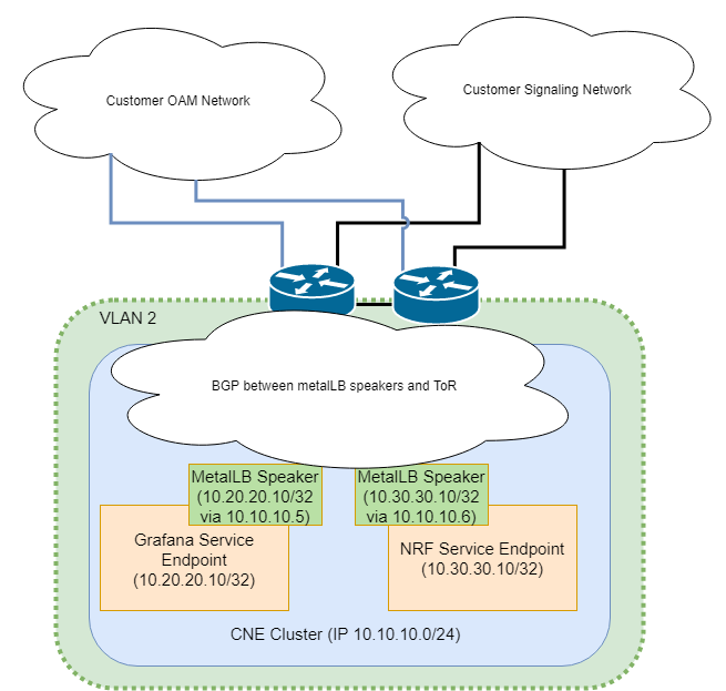
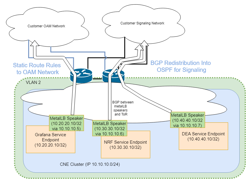
OAM type common services, such as EFK, Prometheus, and Grafana will have their service endpoints configured from the OAM address pool. Signaling services, like the 5G NFs, will have their service endpoints configured from the signaling address pool.