Mapping File Layouts and Document Relationships
|
Page Name |
Definition Name |
Usage |
|---|---|---|
|
Document Builder - Document Page |
IB_LOGICALSCHEMA |
View and edit a document in the Document Builder See Defining a PeopleSoft Document. See the product documentation for PeopleTools: Documents Technology for more information. |
|
FS_DOC_RLTS |
Define a relationship for each node of a PeopleSoft document that is based on database records. |
|
|
FS_FF_LAYOUT |
Define the structure for the delimited file with a constant delimiter used to map the source data set. |
|
|
Code Mappings Page |
TR_CODE_MAPPINGS |
Define input and output values for mappings of a selected code map group. See Using Code Mappings. |
The Data Export and Import Utility uses the PeopleSoft Documents Technology in PeopleTools to retrieve document data. PeopleSoft Documents Technology provides a Document Builder tool that enables you to build the structure of a document and define XML and relational formats for it.
For more information, see the product documentation for PeopleTools: PeopleSoft Documents Technology.
The mapping utility supports two source types: PeopleSoft documents and delimited files.
To map file layouts and document relationships:
Create or identify a PeopleSoft document.
Set up a data relationship for the database table-related document.
Create an XML-formatted PeopleSoft document.
Define the delimited file layout and associate it with the XML-formatted document.
Define code mappings.
Use the Document Builder - Document page (IB_LOGICALSCHEMA) to view and edit a document in the Document Builder.
For use in the Data Export Import Utility process, define PeopleSoft documents that will be the source, target, or both in the mapping definition.
For more information about defining a PeopleSoft document, see the product documentation for PeopleTools: PeopleSoft Documents Technology.
Navigation:
This example illustrates the fields and controls on the Document Builder - Document page.
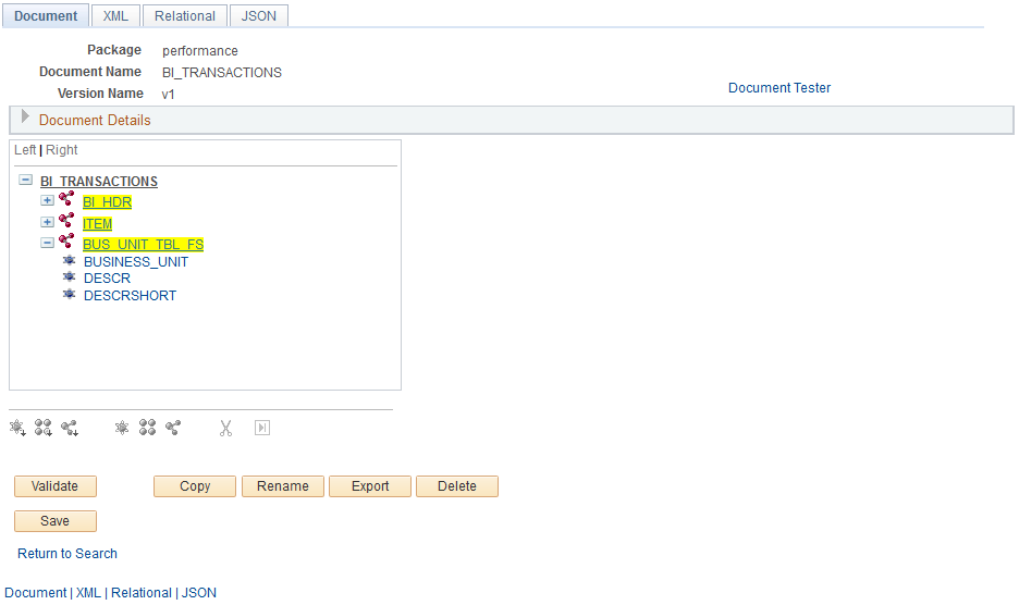
In this example, BI_HDR is the anchor node and BUS_UNIT_TBL_FS is a sibling node that contains fields in the records for billing transactions.
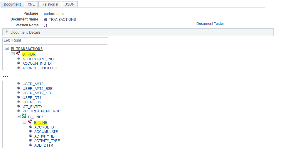
This example illustrates the fields and controls on the Document Builder - Documents page.
This example, which illustrates the fields and controls on the Document Builder - Document page, shows an XML-formatted PeopleSoft document.
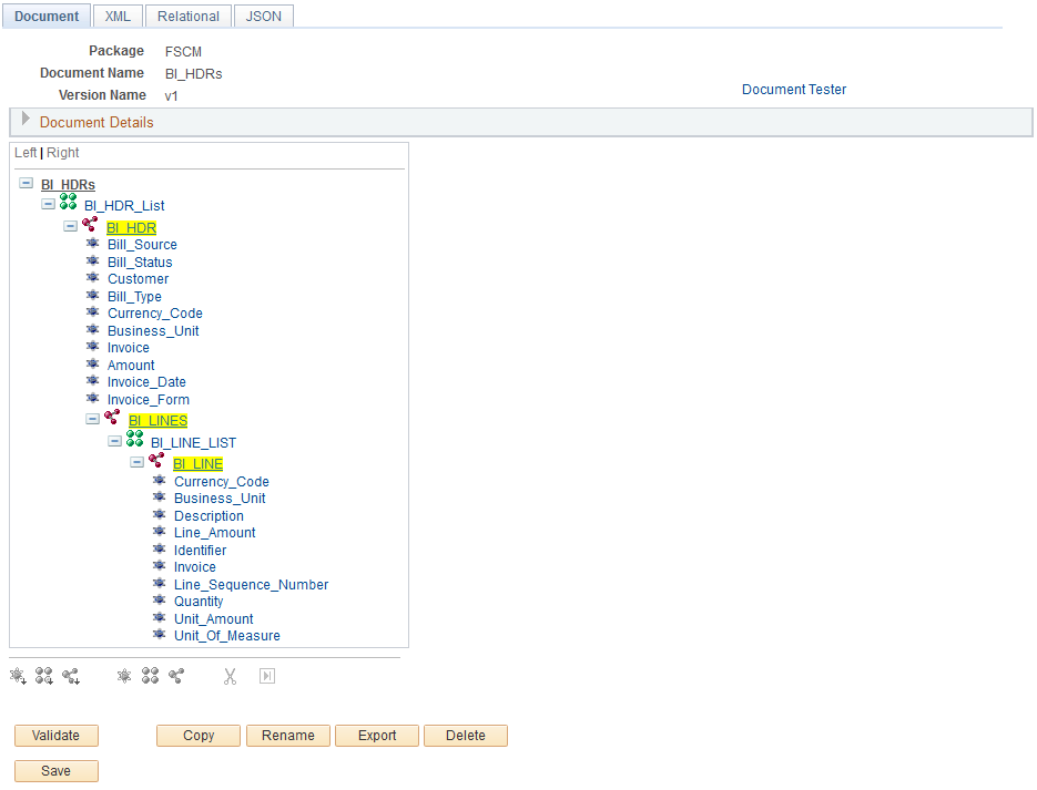
If the PeopleSoft document is defined from the database record, the next step is to define the relationship among the group nodes.
Using PeopleSoft Documents for Specific Scenarios
Data Export Import Utility processing identifies and analyzes the Required check box on XML-formatted PeopleSoft documents to assemble the data mapping, depending on the map definition.
See also Understanding How to Use the Data Export Import Utility for Payment Dispatch.
There are three cases considered by the system:
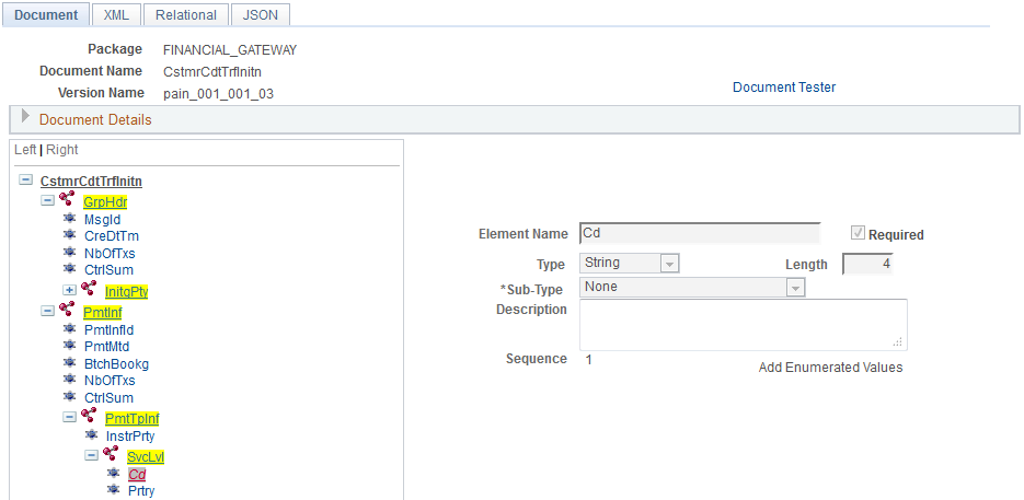
The Required check box is selected for the compound node and primitive element, but they are not mapped in the map definition.
This example illustrates the fields and controls on a PeopleSoft Document, showing a Compound Element with the Required check box selected.

In addition, the mapping details do not exist for this field on the Map Definition - Detail (Step 4 of 6) page.
The XML output in this case would look like this:
- <PmtTpInf>
    <InstrPrty>NORM</InstrPrty>
  - <SvcLvl>
     <CD />
    </SvcLvl>
  </PmtTpInf>
The Required check box is selected for the compound node and primitive element, and they are mapped in the map definition.
This example illustrates the fields and controls on a PeopleSoft Document, showing a Primitive Element with the Required check box selected.
This example illustrates the fields and controls with the target fields populated on the Map Definition - Details page.
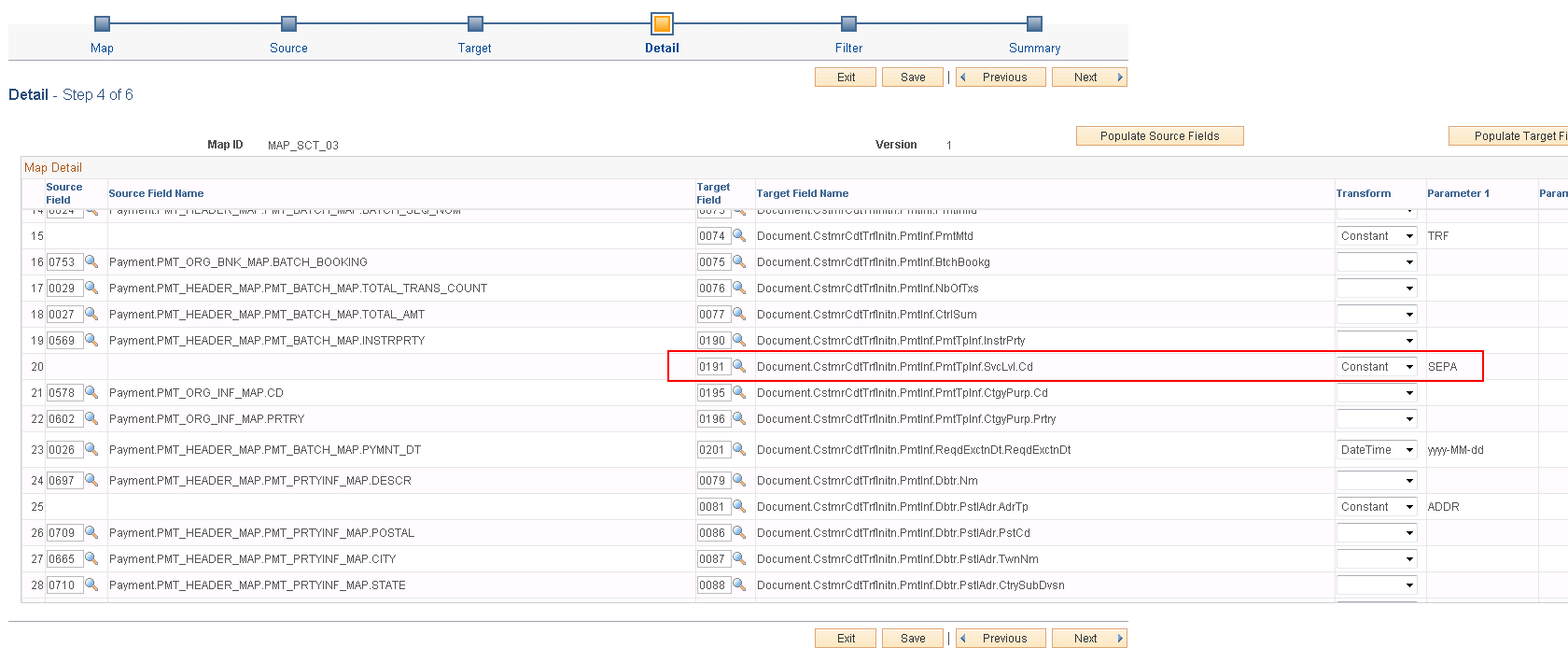
The XML output in this case would look like this:
- <PmtTpInf>
    <InstrPrty>NORM</InstrPrty>
  - <SvcLvl>
     <Cd>SEPA</Cd>
    </SvcLvl>
  </PmtTpInf>
The Required check box is not selected for the compound node and primitive element, and they are not mapped in the map definition.
The XML output in this case would look like this:
- <PmtTpInf>
    <InstrPrty>NORM</InstrPrty>
  </PmtTpInf>
If a compound node is static (that is, there are mappings of this compound node only with a Constant transformation type in the map definition), the Required check box must be selected for the system to output the value. Otherwise, the system ignores the static node and the value will not appear in the output XML.
For more information about the map definition , see Defining the Data Source and Target.
Using a Document with a Complex Primitive Compound Element Type
In a target PeopleSoft document tree, the complex primitive compound element type is used to define an XML element with multiple properties. Here is an example of the PeopleSoft document and corresponding XML output:
This example illustrates a PeopleSoft Document with a Complex Primitive Compound Element Type.
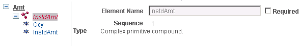
The XML output for this example would look like this:
<InstdAmt Ccy="EUR">1000</InstdAmt>Because you cannot ungroup Primitive Peers in PeopleSoft documents, the ungrouping primitive can be defined as a complex primitive compound element.
Two types of relationships in PeopleSoft documents can be defined for Data Export Import Utility processing: parent-child and sibling. This example of a PeopleSoft document illustrates the document structure and the document relationships set up to be used as the data source for exporting data into an XML file.
The INVOICE document in the BILLING package, includes these group nodes:
BI_HEADER
BI_LINE
BI_ACCT_ENTRY
BUS_UNIT_TBL_FS
BI_HEADER is the parent of BI_LINE, and BI_LINE is the parent of BI_ACCT_ENTRY. In this example, BI_LINE must have the same BUSINESS_UNIT and INVOICE ID as BI_HEADER. The Data Export Import Utility mapping process must know this relationship in order to fetch the correct BI_LINE that belongs to BI_HEADER. The document relationship would be shown as follows:
This example illustrates the Parent-Child Relationship on the Document Relationship page.

In this example, BUS_UNIT_TBL_FS and BI_HEADER are siblings. The purpose of adding the BUS_UNIT_TBL_FS record into this document is that you can translate the BUSINESS_UNIT field of BI_HEADER (for example, US001) into the DESCR field of BUS_UNIT_TBL_FS (for example, US001 New York Operator), thus providing more information in the output.
This example illustrates the Sibling Relationship on the Document Relationship page.
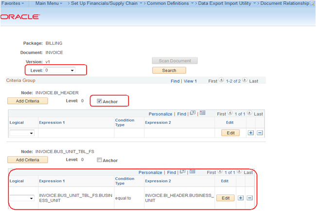
However, in this scenario, the goal is to export BI (billing) information, not BU (business unit) information. Thus the BI_HEADER node becomes the anchor. When exporting BI information, you can translate the BUSINESS_UNIT ID (for example, US001) to BU Name. When Data Export Import Utility processing fetches data from the sibling table, it must find the foreign key.
Use the Document Relationship page (FS_DOC_RLTS) to define a relationship for each node of a PeopleSoft document.
You must define a document relationship if the document refers to data that is stored in more than one PeopleSoft table.
Navigation:
This example illustrates the fields and controls on the Document Relationship page.
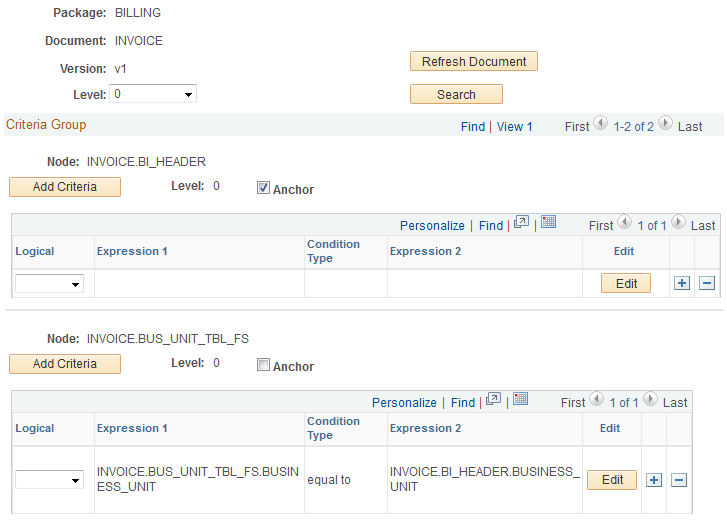
In this example, only Level 0 document relationships are shown. Use the same logic to define other levels. The INVOICE_BI_HEADER is the anchor node for Level 0, which means that INVOICE_BI_HEADER is the driver table. It contains the main data, and data in tables from the other nodes will be loaded according to the anchor node.
Field or Control |
Description |
|---|---|
Scan Document |
Appears upon creating a new document relationship. Click this button to build the initial PeopleSoft document structure for the database table-related document identified by the selected Package, Document Name, and Version. |
Level (header-level) |
Select a level used in the criteria group. You must define the correct parent-child node relationship for each level. |
Search |
Click this button to filter for the selected Level criteria group. |
Node |
Displays the node of the PeopleSoft document to which the relationship criteria apply. |
Add Criteria or Edit |
Click the Add Criteria or Edit button to create new criteria or edit existing criteria, respectively, that define the relationship between the records and fields. |
Level (criteria-level) |
Shows the level of the node in the PeopleSoft document. |
Anchor |
Identify the node that drives the data. The Data Export Import Utility process first loads the anchor node value and then uses the anchor node value to load sibling node values. For example, the INVOICE_BI_HEADER node (table) contains the BUSINESS_UNIT field, which is the ID of BU. The BUS_UNIT_TBL_FS table contains the BU information. Data Export Import Utility processing first loads the INVOICE_BI_HEADER table and retrieves the BU ID; processing then proceeds to the BUS_UNIT_TBL_FS table, and it uses this BU information. The system distinguishes the anchor nodes from sibling nodes following these rules: The system can display multiple anchors at one level. When the system displays a child node as an anchor, its parent nodes must also be displayed as an anchor. When the system displays a parent node as an anchor, the anchor check boxes of its child nodes are deselected. The mapping utility scans anchor by anchor, and synchronizes at the sibling node. |
Logical |
Enter the logical relationship between different expressions. In most cases, this value is AND. |
Instead of using PeopleSoft tables, a user may define a Delimited File as the source or target data structure. The mapping utility uses the PeopleSoft document related to the Delimited File Layout ID to identify the structure of the source or target file.
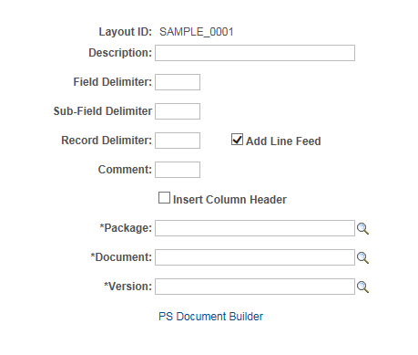
Use the Delimited File Layout page (FS_FF_LAYOUT) to define the structure for the delimited file with a constant delimiter used to map the source or target data set.
Navigation:
This example illustrates the fields and controls on the Delimited File Layout page.
Define the delimited file layout and associate the layout with the XML-formatted PeopleSoft document.
Field or Control |
Description |
|---|---|
Layout ID and Description |
Enter a layout ID and description for this delimited file layout. |
Field Delimiter |
Enter up to 5 characters. This delimiter is a constant separator between each field of one row or record. Enter RT to indicate a return symbol when exporting to delimited files Processing recognizes only literal values. |
Sub-Field Delimiter |
Enter up to 5 characters. This delimiter separates sub-elements. Enter RT to indicate a return symbol when exporting to delimited files Processing recognizes only literal values. |
Record Delimiter and Add Line Feed |
Enter up to 5 characters. This delimiter is a row or record terminator that is followed by a line feed as the default. For no line feed, deselect the line feed option. |
Comment |
Identify the comment type that will be used in the delimited file. For example, if the comment is “//”, then the information or text after “//” will be ignored. |
Insert Column Header |
Select to indicate that you want the first line of the delimited file to be the column header. The PS Document node name will be used as the column header. |
Package, Document, and Version |
Enter a package name, document name, and version to identify the PeopleSoft document that should be associated with this definition. |
PS Document Builder |
Click this link to view the identified document on the Document Builder - Document page. |
Use the Code Mappings page (TR_CODE_MAPPINGS) to define input and output values for mappings of a selected code map group.
This page enables you to define the mapping between external bank codes and their equivalent internal PeopleSoft codes for both bank statement and bank payment processing.
Navigation:
For more information, see Setting Up Common Components for Bank Statement, Payment, and Payment Acknowledgment Processing.