6 Understanding the Communication Service Project Output
The chapter describes a project generated from the Oracle Communications Services Gatekeeper Platform Development Studio Wizard.
About the Generated Communication Service
The section describes a project generated from the Platform Development Studio Wizard.
About the Communication Service Project
Generating a communication service project creates the directory structure illustrated in Example 6-1.
The base directory is the directory given in the PDS Wizard input field Identifier. It contains the following files:
-
build.properties: properties file for the build files:
-
wlng.home is set to Middleware_home, the base directory for the installation.
-
pds.home is set to Middleware_home/ocsg_pds, the base directory for the Platform Development Studio.
-
wls.home is set to Middleware_home/wlserver, the base directory for the WebLogic Server installation.
-
-
build.xml: the main file for the project, that is the build file for the communication service and references to any other plug-in specific build files in the project. See "Main Build File".
-
common.xml: properties, Apache Ant task and targets used by all build files in the project.
The directories and files in bold in Example 6-1 are generated when building the common parts of the communication service; the others are generated by the PDS (Eclipse) Wizard.
Example 6-1 Generated project for Communications Services Common
<Eclipse Project Name>
+- build.properties
+- common.xml
+- build.xml
+- <Identifier given in Ecplise Wizard>
|  +- dist //Generated by target dist in <Eclipse Project Name>/build.xml
|  |  +- <Package name>.store_<version.jar // Example store configuration
|  |  +- wlng_at_<Identifier>.ear //Deployable in access tier
|  |  +- wlng_nt_<Identifier>.ear //Deployable in network tier
|  +- common
|  |  +- build.xml //Build file for the common parts of the communication service
|  |  +- dist //Generated by target dist on
             //<Eclipse Project Name>/common/build.xml
|  |  |  +- request_factory_skel //Skeletons for the RequestFactory,
                                 //one class for each service WSDL
|  |  |  +- tmp //Used during build. Contains classes, source,
                //definitions, WSDLs, templates, and more.
|  |  |  +- <Identifier>.war // Web Service implementation
|  |  |  +- <Identifier>_callback.jar // Service callback EJB for
                                      //the communication service
|  |  |  +- <Identifier>_callback_client.jar //Service call-back EJB used by
                                           // the plug-in.
|  |  |  +- <Identifier>_service.jar // Service EJB
                                      // for the communication service
|  |  +- resources // Contains application.xml and weblogic-application.xml
                   // for the access and network tier EAR files respectively.
                   // The files are packaged in the EAR files META-INF directory
|  |  |  +- handlerconfig.xml //SOAP Message Handler
|  |  +- src // Source directory for communication service common
|  |  |  +- <Package name>/plugin
|  |  |  | +- <Web Services interface>PluginFactory // One per interface
                                                    // defined in the
                                                   // Service WSDL files.
The SOAP Message Handler definition file, handlerconfig.xml, can be edited in order to change, add, or remove SOAP Message Handlers. If modified, it will be taken into account the next time the communication service or plug-in is rebuilt.
The following exception definitions are added:
-
PolicyException - Any policy based exceptions.
-
RoutingException - Any exceptions during the routing of the request.
-
ServiceException - Any other internal exceptions.
The exceptions are added only to the service facade, not to the plug-in to network interface.
If the exceptions listed above are present in the original WSDL they are reused; if not they are added.
About the RESTFul Service Facade
You can generate a RESTful Service Facade using the PDS wizard. The sections below describe the default generation of the RESTful Service Facade and how to modify it.
Default RESTful Service Facade
When a RESTful Service Facade is generated, the following files are generated in addition to the directory structure described in Example 6-1:
-
rest_identifier.war in the common/dist directory
-
rest/identifier/index.html, in the common/dist/tmp/wars/rest_identifier directory
-
rest-config.xml, in the identifier/common/resources/facade/rest directory
The RESTful Service Facade Web Application rest_identifier.war is packaged in the Access Tier EAR file. The context root is rest/identifier.
An API description is generated in the common/dist/tmp/wars/rest_identifier directory. It describes each operation, including URI, HTTP-method, request- and response content-type, request- and response, and errors.
The generated RESTful API has a default implementation, which can be changed by editing rest-config.xml and re-building the Service Facade. The API description is updated so it reflects any changes done in the configuration file.
The default implementation of the generated RESTful Service Facade has the following attributes for application-initiated requests.
The HTTP method is POST.
The URL to a default RESTful resource is:
http://host:port/rest/context-root/interface/operation/path_info?name[1]=value[1]&name[2]=value[2]&...name[n]=value[n]
Where:
-
host and port depend on the Services Gatekeeper installation, and on the server where the RESTful Service Facade is deployed.
-
context-root is specified in the field Web Services Context Path in the PDS wizard.
-
interface is derived from the interface name in the Service WSDL.
-
operation is derived from the operation name in the Service WSDL.
-
path_info and the name-value pair should not be present in the URI since the default HTTP method is POST. See Table 6-1 for information on how this behavior can be changed. path-info and the queryString are not present by default.
The HTTP content-type for the request is application/json. The HTTP request body contains a JSON formatted object that corresponds to the input message of the operation as defined in the Service WSDL.
The HTTP content-type for the response is application/json. The HTTP response body contains a JSON formatted object that corresponds to the output message of the operation as defined in the Service WSDL. The HTTP response body for an error contains a JSON formatted object that corresponds to the error message of the operation as defined in the Service WSDL.
For example the Parlay X 2.1 Short Messaging Service defines the operation startSmsNotification. Using the WSDLs for this service, the corresponding RESTful resource is according to Table 6-1. This information is provided in the generated API documentation.
Table 6-1 Example of a RESTful resource as used by an application
| Attribute | Value |
|---|---|
|
URI |
rest/sms/SmsNotificationManager/startSmsNotification |
|
HTTP Method |
POST |
|
Request Content-Type |
application/json |
|
Request Body |
{ "reference": { "correlator": "String", "endpoint": "URI", "interfaceName": "String" }, "smsServiceActivationNumber": "URI", "criteria": "String" } |
|
Response Body |
Empty. |
|
Error Response |
{"error":{ "type":"org.csapi.schema.parlayx.common.v2_1.ServiceException" "message":"String" }} |
|
Error Response |
{"error":{ "type":"org.csapi.schema.parlayx.common.v2_1.PolicyException" "message":"String" }} |
The Bayeux Protocol 1.0 is used to deliver network-triggered messages or notifications to an application.
The RESTful Service Facades rely on the publish-subscribe model supported by the Publish-Subscribe Server functionality of Oracle WebLogic Server. The communication service delivers the network-triggered traffic to the publish-subscribe server channel, from which the application Bayeux client fetches it. For more information on this model, see the discussion on using the HTTP publish-subscribe server in Oracle Fusion Middleware Developing Web Applications, Servlets, and JSPs for Oracle WebLogic Server at:
http://download.oracle.com/docs/cd/E15523_01/web.1111/e13712/pubsub.htm
An application needs to subscribe for notifications. The application provides an endpoint URI to receive notifications on. In Parlay X, the operations are normally named according to startservice_nameNotification, for example startSmsNotification. In a RESTful environment, the endpoint URI is the name of the Bayeux channel, must start with the string /bayeux/ to be recognized as a RESTful endpoint. Immediately following this keyword, the application must provide the application instance ID that uniquely identifies the application. An example of an endpoint is /bayeux/myApplicationID/myInterface. The application's Bayeux client must perform a hand-shake, connect to the publish-subscribe server and subscribe to the channel that is being created for the notification.
The publish-subscribe server URI to use for the Bayeux connect is:
http://host:port/rest/context-root/notifications
Where:
-
host and port depend on the Services Gatekeeper installation.
-
identifier is specified in the field identifier in the PDS wizard.
Notifications are sent by using Bayeux Deliver Event messages.
The HTTP response body contains a JSON formatted object that corresponds to the output message of the operation as defined in the Service Callback WSDL.
Typically, the publish-subscribe server URI to use for the Bayeux connect should be returned to the application in the in the header of the response to start a notification. Do do this, you should update rest-config.xml with a <response-header> element. See "Customize the RESTful Service Facade" for more information.
Customize the RESTful Service Facade
The following can be customized for the RESTFul Service Facade:
-
HTTP method
-
URI Mapping
-
servlet-path
-
pathinfo
-
request parameter
-
-
Data binding
-
path-info-param
-
request-param
-
-
Other
-
additional response headers
-
custom handler chain for an operation
-
custom data type adapters
-
custom HTTP status code mappings for errors
-
The mappings are defined in rest-config.xml according to the XSDs rest-config.xsd and error-mappings.xsd, located in Middleware_home/ocsg/applications/rest.jar. Table 6-2 contains a description of the mappings.
Table 6-2 Structure and Description of rest-config.xml
| Element/Type | Description |
|---|---|
|
<resources> |
Main element. Contains: <resource>, one (1) or more. <handler-chain>, zero (0) or more. <data-type-adapter>, zero (0) or more. <notification>, zero (0) or more. <binding>, one (1) or more. <error-mappings>, zero (0) or one (1). |
|
<resource> |
Parent element: <resources>. Contains the following element: <operation>, one (1) or more. Has the attribute:
Defines a part of the URI for a RESTful resource. All resources used for application-initiated traffic need this definition. If the URI used by an application is: http://host:port/<context-root>/<servlet-path>/<pathinfo>?<name1>=<value1>&<name2>=<value2> The attribute uri corresponds to <servlet-path> in the URI. |
|
<operation> |
Parent element: <resource>. Contains the following elements:
Defines an operation that corresponds to the RESTful resource. |
|
<http-method> |
Defines which HTTP operation to use for the resource. Use GET, POST, PUT, or DELETE. By default, the method is POST. For other methods, the request URI will differ and some elements become mandatory or not used. |
|
<request-type> |
Parent element: <operation>. Used for API documentation generation only. It has no run-time effect. Defines the content-type header of the incoming HTTP request. Default value is application/json. Enumeration:
|
|
<request-param> |
Parent element: <operation>. Has the attributes:
Defines expected request name value pairs. Useful for sending a JSON object using HTTP GET, in which case the value should be an encoded JSON string representing the input object. Only one JSON object is supported. Also useful for overloading the resource URI, for example invoking different operations on the same resource, in which case the value will be specified as a constant. Every incoming request in the format of: http://host:port/<context-root/<servlet-path>/<pathinfo>?<name1>=<value1> invokes the given operation. If the URI used by an application is: http://host:port/<context-root/<servlet-path>/<pathinfo>?<name1>=<value1>&<name2>=<value2> The attribute name corresponds to either <name1> or <name2> in the URI. If either <value1> or <value2> is defined as a constant, that attribute value shall be set to this constant. Format the value as a JSON object. |
|
<path-info-param> |
Parent element: <operation>. Has the attribute:
Defines a part of the URI for a RESTful resource. This element is optional. When present, the value will be taken from the <pathInfo> component of request URI, and used to populate the field of the target operation input parameter. The attribute name specifies the name of the field to be populated. If the URI used by an application is: http://host:port/<context-root/<servlet-path>/<pathinfo>?<name1>=<value1>&<name2>=<value2> The attribute name corresponds to <pathinfo> in the URI. |
|
<target> |
Parent element: <operation>. Has the attributes:
Defines how the RESTful resource maps to the Java implementation of the service. The attribute service is derived from the interface type in the WSDL. The attribute class defines the generated class that implements the interface defined in the WSDL. The pattern is: <package name from PDS wizard>.<Service name from wizard>.rest.<Interface name from WSDL>RestImpl The attribute method defines the method in the class to bind RESTful resource. The name of the method is derived from the operation defined in the WSDL. |
|
<handler-chain> |
Parent element: <resources> or <operation>. This element defines a handler chain. When defined under <operation>, it refers to provided handler chain names or custom handler chains. If it is a custom handler chain it also needs to be defined under <resources>. If it is a provided handler chain, it is only necessary to refer to the name. When defined under <resources>, it defines a named handler chain to be invoked prior to the request being handed off to the generated RESTFul Service Facade implementation and prior to a response being handed off to the calling application. There are a set of available handler chains available. New ones can be added. The available handler chains include:
For default behavior use default or default-with-attachment. See "Using a Custom Handler Chain" for information on how to create a custom handler chain. |
|
<response-header> |
Parent element: <operation>. Has the attributes:
Defines HTTP response headers to be returned to the application. The attribute name is the name of the response header. The attribute value attribute can be a constant or a variable. If it is a variable, the format is ${field name of return value}, where the variable is replaced with the runtime value of the field. Nested fields are not supported. The variable tokens for each operation is found in the generated API docs. The variable ${rest-facade-url} is predefined. It is replaced with the URL to the incoming request the RESTFul Service Facade. Example: <response-header name="Location" value="${rest-facade-url}/delivery-status/${result}"/> |
|
<response-type> |
Parent element: <operation>. For API documentation only, no run-time effect. Defines the content-type header of the outgoing HTTP response. Enumeration: Defines the content-type header of the outgoing HTTP response. Default value is application/json. Enumeration:
|
|
<empty-response> |
Parent element: <operation>. Defines that the HTTP response for the enclosing operation does not have an entity body. |
|
<data-type-adapter> |
Parent element: <resources>. Contains the following elements:
The element target-field has the attributes:
Defines a data type adapter. This is needed only if the target Java type can be mapped to more than one XML schema types, for example byte[] to xsd:hexBinary or xsd:base64Binary. There are two adapters available:
The element name defines the data type adapter to use for the given target fields. The element target specifies the class for the object and the member variable in the object. Examples: <data-type-adapter> <name>base64binary</name> <target-field class="org.csapi.schema.parlayx.sms.send.v2_2.local.SendSmsLogo" name="image"/> </data-type-adapter> <data-type-adapter> <name>hexBinary</name> <target-field class="com.acompany.schema.example.data.send.local.SendData" name="binaryField"/> </data-type-adapter> |
|
<notification> |
Parent element: <resources>. Contains the following elements:
For API documentation only, no run-time effect. Defines the message format used to notify an application of a network-triggered operation. The operation is defined in the Service Callback WSDL. All resources used for network-triggered traffic needs this definition. |
|
<service> |
Parent element: <notification> Derived form the WSDL for the Service Callback WSDL. Example: MessageNotification |
|
<data> |
Parent element: <notification> Has the attributes:
Defines the data in a notification sent to an application. The attribute id defines the id of the notification. This is the same as the operation defined in the Service Callback WSDL. The attribute class defines the generated class that specifies the notification. The class is generated based on the Service Callback WSDL. Example: <data id="notifyMessageReception" class="org.csapi.schema.parlayx.multimedia_messaging.notification.v2_4.local.NotifyMessageReception"/> |
|
<binding> |
Parent element: <resources> Has the attributes:
For API documentation only, no run-time effect. No need to modify. Defines the binding between the attribute service defined in the element <target> and the Service WSDL. The attribute service identifies the service name. The attribute schema identifies the Service WSDL. Example: <binding service="SendMessage" schema="parlayx_mm_send_interface_2_4.wsdl"/> |
|
<error-mappings> |
Parent element: <resources> Contains the following elements:
|
|
<error-mapping> |
Parent element: <error-mappings> Contains the following elements:
Describes how a set of exceptions thrown by the RESTful Service Facade or Service Enabler maps to a HTTP status code. Default behavior is defined in default-error-mapping.xml. Custom mapping takes precedence. |
|
<http-status-code> |
Parent element: <error-mapping> Defines the HTTP status code to return. |
|
<http-method> |
Parent element: <error-mapping> Defines the HTTP method used for the original request. If omitted the mapping is valid for all HTTP request methods. |
|
<error> |
Parent element: <error-mapping> Has the attributes:
The attribute class defines the class that defines the exception. The attribute id-field defines which member variable in the exception to match. The attribute id-value defines the value of the member variable to match. |
Custom URL Mapping Example
For a URL in the format:
http://host:port/context-root/servlet-path/pathinfo?name1=value1&name2=value2
The following applies:
-
servlet-path must match the attribute URI of the
<resource>element. -
pathinfo must match the attribute name of the
<path-info-param>element. It identifies a unique resource, such as a correlator. Note that this element is optional. If not present in the XML configuration file, it should not be present in the URL. -
request parameters:
-
name must match the attribute name of the
<request-param>element. -
value must match the attribute value of the
<request-param>element.
-
For application-initiated operations, each resource URI is mapped to an HTTP method and an implementing class, for example:
<resource uri="/SendSms/sendSms">
  <operation>
    <httpMethod>POST</httpMethod>
    <target method="sendSms"
    class="com.acompany.arestservice.rest.SendSmsRestImpl" service="SendSms"/>
  </operation>
</resource>
The names of the generated classes are derived from the package name given in the PDS wizard and the interface name derived from the WSDL:
package name from wizard.service name from wizard.rest.interface name from WSDLRestImpl
The method name is derived from the WSDL. The resource URI is derived from the namespace definition in the WSDL. The <httpMethod> element defines the HTTP method to use, either POST, GET, PUT or DELETE.
For network-triggered operations, each notification service is mapped to one or more classes that contain the data and the method used to deliver the data, for example:
<notification>
  <service>SmsNotification</service>
    <data class=
      "org.csapi.schema.parlayx.sms.notification.v2_2.local.NotifySmsReception"
      id="notifySmsReception"/>
    <data class=
       "org.csapi.schema.parlayx.sms.notification.v2_2.local.NotifySmsDeliveryReceipt"
       id="notifySmsDeliveryReceipt"/>
</notification>
The classes and the method name are derived from the WSDL.
Using a Custom Handler Chain
A custom handler chain can be defined if additional processing of the request needs to be done before a request is passed on to the Service Enabler or back to an application.
A handler chain is defined as a set of handlers. A handler chain is named and referred to in rest-config.xml.
The existing handlers are:
-
SessionIdHandler, which handles session IDs and extracts the IDs from the request.
-
ServiceCorrelationIdHandler, which handles service correlation and extracts the IDs from the request.
-
ExtendingParametersHandler, which handles tunnelled parameters.
-
AttachmentHandler, which handles HTTP attachments.
A custom handler must implement the interface.
public interface com.bea.wlcp.wlng.rest.handler.Handler
The handleRequest method is invoked before a request is passed on to the Service Enabler.
The handleResponse method is invoked before a response is returned to an application.
The chain is defined in rest-config.xml. All classes in the chain must be packaged in the WAR file for the restful service facade.
About the Communication Service Plug-in
When you create a plug-in for a communication service, the directory structure illustrated in Example 6-2 is created under the top-level directory. The base directory depends on the type of communication service the plug-in belongs to, for example, px21_multimedia_messaging, or px21_sms. It also depends on whether the plug-in is for an existing communication service or for a new one.
If the plug-in is for an existing communication service, it is generated under one of the existing directories; for example a Parlay X 30 Audio Call plug-in the px30_audio_call directory, a Parlay X 2.1 Short Messaging in the px21_sms, and so on.
If the plug-in is for a new communication service, the base directory is given in the Identifier entry field in the PDS Wizard.
The base directory contains the directory plugins, which contains subdirectories for each protocol being added. The names of the directories are the same as the name chosen for the Protocol field in the PDS Wizard.
Each of the sub-directories for a plug-in contains the following files:
-
build.xml: The build file for the plug-in, see "Plug-in Build File".
Each plug-in sub-directory also contains the directories:
-
config: The directory that includes an instance map that is used by the InstanceFactory to create instances for the plug-in interface implementations.
-
dist: The directory where the final deployable plug-in JAR will end up. If a new plug-in skeleton is generated from the build file it will be generated here.
-
resources: The directory that contains deployment descriptors for the plug-in.
-
src: The directory that contains the generated plug-in code.
-
storage: The directory that contains the configuration file for the Storage service.
The directories and files in bold in Example 6-2 are generated when building the plug-in, the others are generated by the PDS Wizard.
Example 6-2 Generated project for a plug-in
|  +- plugins // Container directory for all plug-ins for
              // the communication service
|  |  +- <Protocol> // One specific plug-in
|  |  |  +- build.xml // Build file for the plug-in
|  |  |  +- build // Used during the build process
|  |  |  +- config //
|  |  |  |  +- instance_factory
|  |  |  |  |  +- instancemap //Instance map
|  |  |  +- dist // Generated by target dist in build.xml for the plug-in
|  |  |  |  +- <Identifier>_<Protocol>_plugin.jar
|  |  |  |  +- <Package name>.store_<version>.jar
|  |  |  +- resources // Contains parts of weblogic-extension.xml
                      // for the network tier EAR file.
                     // the file is packaged in the EAR file's META-INF directory
|  |  |  +- src
|  |  |  |  +- <Package name> // Directory structure reflecting
                              // plug-in package name
|  |  |  |  |  +- management // Example MBean
|  |  |  |  |  |  +- MyTypeMBean.java
|  |  |  |  |  |  +- MyTypeMBeanImpl.java
|  |  |  |  |  +- <Web Services interface> // One per Service WSDL
|  |  |  |  |  |  +- north
|  |  |  |  |  |  |  +- <Web Services interface>PluginImpl.java
                                 // Implmentation of the interface
|  |  |  |  |  +- <Type>PluginInstance.java
|  |  |  |  |  +- <Type>PluginService.java
                                // PluginService implementation
|  |  |  +- storage //Example of a store configuration.
|  |  |  |  +- wlng-cachestore-config-extensions.xml
About the SOAP2SOAP Plug-in
When you create a SOAP2SOAP plug-in, the directory structure described in "About the Communication Service Plug-in" is created under the top-level directory. In addition, the directories and files in "Generated project for a SOAP2SOAP plug-in" are generated. The directories and files in bold are created when building the plug-in; the others are generated by the PDS Wizard.
Note:
Only the deployable artifacts are relevant. The generated code for the SOAP2SOAP type of plug-ins should not be modified.Example 6-3 Generated project for a SOAP2SOAP plug-in
|  +- plugins // Container directory for all plug-ins for
              // the communication service
|  |  +- <Protocol> // One specific plug-in
|  |  |  +- build.xml // Build file for the plug-in
|  |  |  +- build // Used during the build process
|  |  |  +- config //
|  |  |  |  +- instance_factory
|  |  |  |  |  +- instancemap //Instance map
|  |  |  +- dist // Generated by target dist in build.xml for the plug-in
|  |  |  |  +- <Identifier>_<Protocol>_plugin.jar
|  |  |  |  +- <Package name>.store_<version>.jar //unused, empty
|  |  |  +- resources // Contains parts of weblogic-extension.xml
                      // for the network tier EAR file.
                     // the file is packaged in the EAR file's META-INF directory
|  |  |  |  +- client_handlerconfig.xml // SOAP Message Handler
|  |  |  +- src
|  |  |  |  +- <Package name> // Directory structure reflecting
                              // plug-in package name
|  |  |  |  |  +- client // Implementation of Web Service client
|  |  |  |  |  |  +- <Web Services interface>_Stub.java
|  |  |  |  |  |  +- <Web Services interface>.java
|  |  |  |  |  |  +- <Web Services interface>Service_Impl.java
|  |  |  |  |  |  +- <Web Services interface>Service.java
|  |  |  |  |  +- <Web Services call-back interface> // One per Call-back WSDL
|  |  |  |  |  |  +- south
|  |  |  |  |  |  |  +- <Web Services interface>PluginSouth.java
                                 // Interface for network-triggered requests
|  |  |  |  |  |  |  +- <Web Services interface>PluginSouthImpl.java
                                 // Implementation of the interface
|  |  |  |  |  +- <Web Services interface> // One per Service WSDL
|  |  |  |  |  |  +- north
|  |  |  |  |  |  |  +- <Web Services interface>PluginImpl.java
                                 // Implementation of the interface
|  |  |  |  |  +- <Type>PluginInstance.java
|  |  |  |  |  +- <Type>PluginService.java
                                // PluginService implementation
|  |  |  +- storage //Example of a store configuration. Empty.
|  |  |  +- wsdl // WSDLS and XML-to-Java mappings.
|  +- <Identifier>_callback.war // Web Service implementation
                                        // for the SOAP2SOAP plug-in
As illustrated in Example 6-3, a WAR file for the plug-in is generated. This WAR file contains the Web Service for network-triggered requests. It is only generated if there is a notification WSDL defined at generation-time. It will be packaged in the EAR file for the Service Enabler.
The SOAP Message Handler definition file, client_handlerconfig.xml, can be edited in order to change, add, or remove SOAP Message Handlers. If modified, the Ant target rebuild.ws in the plug-in build file needs to be invoked.
In the start script, the -Dweblogic.wsee.soap.81CustomException flag must be set to true in order to push the soap faults defined in WSDL as-is.
Generated Artifacts for a SOAPSOAP Communication Service
When a SOAP2SOAP communication service is generated, the following directory structure is created in the directory domain_home/soap2soap on the administration server.
Example 6-4 Directory Structure from Generating SOAP2SOAP Communication Services
+- <Communication service name>_<version>/
+- build.properties
+- build.xml
+- common.xml
+- <Communication service name>/
+- common/+- resources/
+- enabler/
+- facade/
+- handlerconfig.xml
+- dist/
+- com.bea.wlcp.wlng.soap2soap.<service type>.store_<version>.jar
+- wlng_at_<Communication service name>.ear
+- wlng_nt_<Communication service name>.ear
+- plugins/
|+- soap/
 +- tmp/
All Java source files, build files, configuration files, and deployable artifacts are created under the directory domain_home/soap2soap. The source files are there mainly for reference. The only files that are necessary to deploy the communication service are:
-
wlng_at_communication_service_name.ear
-
wlng_nt_communication_service_name.ear
wlng_at_communication_service_name.ear should be deployed in the access tier server.
wlng_nt_communication_service_name.ear should be deployed in the network tier server.
The generated communication service can be deployed as a part of the generation process, as described above, or using standard WebLogic Server tools.
See the discussion on deploying and undeploying communication services and plug-ins in Services Gatekeeper System Administrator's Guide for information on how to deploy the files using WebLogic Server tools.
Properties for SOAP2SOAP Plug-ins
Table 6-3 lists the SOAP2SOAP plug-in properties.
Table 6-3 SOAP2SOAP Plug-in Properties
| Property | Description |
|---|---|
|
Managed object in Administration Console |
domain name, then OCSG, then server name, then Communication Services, then plug-in instance ID |
|
MBean |
Domain=com.bea.wlcp.wlng Name=wlngt InstanceName is same as plug-in instance ID Type=com.bea.wlcp.wlng.httpproxy.management.HTTPProxyMBean |
|
Network protocol plug-in service ID |
Defined when generating the SOAP2SOAP plug-in using the Platform Development Studio. When generated fm the Administration console, the ID is Name_soap_plugin. |
|
Network protocol plug-in instance ID |
The ID assigned when the plug-in instance is created: see the discussion on configuring and managing the plug-in manager in Services Gatekeeper System Administrator's Guide for more information. |
|
Supported Address Scheme |
Defined when generating the SOAP2SOAP plug-in using the Platform Development Studio. When generated fm the Administration console, the address scheme is always an empty string. |
|
Application-facing interfaces |
Derived from the package name of the network protocol plug-in, assigned when the plug-in was generated, and the name of the interface as defined in the WSDL. For application-initiated request:
For network-triggered requests:
See see the discussion on configuring and managing the plug-in manager in Services Gatekeeper System Administrator's Guide information on how to list the interfaces. |
|
Service type |
Given when the plug-in was generated using the Platform Development Studio or the administration console. |
|
Exposes to the service communication layer a Java representation of: |
Depends on the WSDLs used. |
|
Interfaces with the network nodes using: |
The same protocol as exposed by the application-facing interfaces. |
|
Deployment artifacts |
communication service identifier_protocol_plugin.jar, communication service identifier_service.jar and communication service identifier_callback.war, packaged in wlng_nt_communication service.ear communication service identifier_callback.jar and communication service identifier.war, packaged in wlng_at_communication service identifier.ear communication service identifier was given in the PDS wizard or the Administration console when the communication service was generated. protocol is configurable when using the PDS wizard. If the communication service was generated using the Administration console, it is always |
About the SIP Plug-in
When creating a SIP plug-in, the directory structure described in "About the Communication Service Plug-in" is created under the top-level directory. In addition, the directories and files in Example 6-5 are generated. The directories and files in bold are created when building the plug-in; the others are generated by the PDS Wizard.
Example 6-5 Generated project for a SIP plug-in
|  +- plugins // Container directory for all plug-ins for
              // the communication service
|  |  +- <Protocol> // One specific plug-in
|  |  |  +- build.xml // Build file for the plug-in
|  |  |  +- build // Used during the build process
|  |  |  +- config //
|  |  |  |  +- instance_factory
|  |  |  |  |  +- instancemap //Instance map
|  |  |  |  +- sip
|  |  |  |  |  +- WEB-INF
|  |  |  |  |  |  +- sip.xml
|  |  |  |  |  |  +- web.xml
|  |  |  +- dist // Generated by target dist in build.xml for the plug-in
|  |  |  |  +- <Identifier>_<Protocol>_plugin.jar
|  |  |  |  +- <Identifier>_<Protocol>_sip.war
|  |  |  |  +- <Package name>.store_<version>.jar
|  |  |  +- resources
|  |  |  |  +- META-INF
|  |  |  |  |  +-weblogic-extension.xml
|  |  |  |  |  +-application.xml
|  |  |  +- src
|  |  |  |  +- <Package name> // Directory structure reflecting
                              // plug-in package name
|  |  |  |  |  +- servlet // Implementation of the SIP Servlet
|  |  |  |  |  |  +- <Identifier>Servlet.java
|  |  |  |  |  +- <Identifier>SipHelper.java
|  |  |  +- storage //Example of a store configuration. Empty.
As illustrated in Example 6-3, a set of additional classes and configuration files for the SIP type plug-in is generated compared to the standard plug-in.
Table 6-4 contains a summary of the added items.
Table 6-4 Additional files generated for a SIP plug-in
| File | Description |
|---|---|
|
sip.xml |
SIP Application deployment descriptor. See: WebLogic 11g - ”Developing and Programming SIP Applications” in Oracle WebLogic Communication Services Developer's Guide at the WebLogic 11g documentation web site:
|
|
web.xml |
HTTP Servlet deployment descriptor. See ”Understanding WebLogic Server Deployment” in Oracle WebLogic Server Developing Applications for WebLogic Server. |
|
identifier_protocol_sip.war |
Deployable SIP application. |
|
application.xml |
Deployment descriptor. Contains an additional element for elements for the SIP application. |
|
identifierServlet.java |
Implementation of a SIP Servlet. |
|
identifierSipHelper.java |
Helper class for getting an instance of javax.servlet.sip.SipFactory and javax.servlet.sip.SipSessionsUtil. |
About the Diameter Plug-in
Network protocol plug-ins can benefit from the Diameter support provided by Oracle Communications Converged Application Server (Converged Application Server).
Diameter is a peer-to-peer protocol that involves delivering attribute-value pairs (AVPs). A Diameter message includes a header and one or more AVPs. The collection of AVPs in each message is determined by the type of Diameter application, and the Diameter protocol also allows for extension by adding new commands and AVPs. Diameter enables multiple peers to negotiate their capabilities with one another, and defines rules for session handling and accounting functions.
Converged Application Server includes an implementation of the base Diameter protocol that supports the core functionality and accounting features described in RFC 3588. Converged Application Server uses the base Diameter functionality to implement multiple Diameter applications, including the Sh, Rf, and Ro applications.
You can also use the base Diameter protocol to implement additional client and server-side Diameter applications. The base Diameter API provides a simple, Servlet-like programming model that enables you to combine Diameter functionality with SIP, HTTP, or other functionality in a Service Enabler.
Services Gatekeeper uses the Diameter support provided by Converged Application Server in the Parlay X 3.0 Payment communication service (Ro), CDR to Diameter service (Rf), and the Credit Control interceptor (Ro).
For an overview of the capabilities of the Diameter API provided with Converged Application Server, see the discussion on overview of the diameter API in:
Oracle WebLogic Communication Services Developer's Guide at:
http://download.oracle.com/docs/cd/E15523_01/doc.1111/e13807/diameter_1.htm.
To create a plug-in that uses this the Diameter API, generate a network protocol plug-in using the PDS Wizard and include the JAR file to the build path of the project.
The Diameter API is packaged in Middleware_home/wlserver/sip/server/lib/wlssdiameter.jar.
The JAR file needs to be added to the build class path. It is already included in the run-time class path.
Generated classes for a Plug-in
Figure 6-1 illustrates the generated plug-in classes for life-cycle management and their relationships with other interfaces.
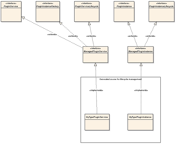
Interface: ManagedPluginService
The interface a plug-in service needs to implement.
Extends the interfaces PluginService, PluginInstanceFactory and PluginServiceLifecycle.
Interface: PluginService
The interface that defines the plug-in service when it is registered in the Plug-in Manager.
Interface: PluginInstanceFactory
The factory that allows a plug-in service to create plug-in instances.
Interface: PluginServiceLifecycle
The interface that defines the lifecycle for a plug-in service. See "Understanding the Plug-in States".
PluginService
Class
Implements com.bea.wlcp.wlng.api.plugin.ManagedPluginService.
Defines the life-cycle for a plug-in service, see "Understanding the Plug-in States" for more information.
Also holds the data that is specific for the plug-in instance.
The actual class name is communication_service_typePluginService. This class manages the life-cycle for the plug-in service, including implementing the necessary interfaces that make the plug-in deployable in Services Gatekeeper. It is also responsible for registering the north interfaces with the Plug-in Manager. At startup time it uses the InstanceFactory to create one instance of each plug-in service and at activation time it registers these with the Plug-in Manager. The InstanceFactory uses an instancemap to find out which class it should instantiate for each plug-in interface implementation. The instance map is found under the resource directory.
ManagedPlugin Skeleton
The ManagedPlugin skeleton implements the following methods related to life-cycle management and should be adjusted for the plug-in:
-
doStarted() - plug-in specific functionality for being started.
-
doActivated() - plug-in specific functionality for being activated.
-
doDeactivated() - plug-in specific functionality for being deactivated.
-
doStopped() - plug-in specific functionality for being stopped.
-
handleForceSuspending() - Called when a FORCE STOP/SHUTDOWN has been issued.
-
handleResuming() - Transitions the plug-in from ADMIN to ACTIVE state in which it begins to accept traffic.
-
handleSuspending(CompletionBarrier barrier()) - Called in a normal re-deployment when the plug-in is taken from ACTIVE do ADMIN state.
-
isActive() - reports back true or false. If false, no application-initiated requests are routed to the plug-in.
In addition, this class defines which address schemes the plug-in can handle, in private static final String[] SUPPORTED_SCHEMES.
PluginInstance
Class
Implements com.bea.wlcp.wlng.api.plugin.ManagedPluginInstance.
Defines the life-cycle for a plug-in instance, see "Understanding the Plug-in States" for more information.
The actual class name is communication_service_typePluginInstance. This class manages the life-cycle for the plug-in instance including implementing the necessary interfaces that make the plug-in an instance in Services Gatekeeper.
It is also responsible for instantiating the classes that implement the traffic interfaces, and initializing stores to use and relevant MBeans.
PluginNorth
This is an empty implementation of the Plug-in North interface. This interface is generated based on the WSDL files that define the application-facing interface. This is the starting point for the plug-in implementation.
The following files are generated in the directory under src/...../service_ name/north:
-
web_service_interface_namePluginNorth: This class implements the plug-in interface. One file is generated for each plug-in interface. There is one plug-in interface for each service WSDL.
Figure 6-2 shows the PluginNorth and RequestFactory class diagram.
Figure 6-2 Class diagram of the generated PluginNorth and RequestFactory.
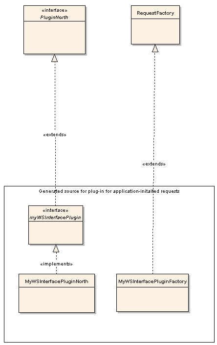
Description of ''Figure 6-2 Class diagram of the generated PluginNorth and RequestFactory.''
PluginNorth skeleton
Below outlines what needs to be implemented in the plug-in skeleton.
The class contains a Java mapping of the methods defined in the Web Service. The methods are mapped one-to-one. The name of each method is the same as the name of the operation defined in the WSDL. The parameter is a class that mirrors the parameters in the input message in the Web Service request. The return type is a class that represents the output message in the Web Service Request.
RequestFactory Skeleton
The actual class name is communication_service_identifierPluginFactory, such as, for example, NotificationManagerPluginFactory. This is a helper class used by the Service EJB. It serves two purposes:
-
It creates the routing information requested by the Plug-in Manager when routing the method call to a plug-in.
-
It converts exceptions thrown either by the Plug-in Manager or by the plug-in to exception types that are supported by the application-facing interface. This is the place to convert exceptions specific to an extension plug-in to exceptions specific to the application-facing interface. It is a best practice to have one single place for performing these conversions in order to document and locate exception mappings.
The following files are generated in the dist directory under request_factory_skel/src:
-
webservice_interface_namePluginFactory: This class extends the RequestFactory class. There will be one file generated for each plug-in interface.
Generated classes for a SOAP2SOAP Plug-in
In addition to the generated classes for a regular plug-in, a SOAP2SOAP plug-in adds a few extra classes, because the network protocol is known.
Note:
Only the deployable artifacts are relevant. The generated code for SOAP2SOAP type of plug-ins should not be modified.See Managing and Configuring SOAP2SOAP communication services in Services Gatekeeper System Administrator's Guide for information on how to configure and manage a SOAP2SOAP plug-in.
Comparison with a Non-SOAP2SOAP Plug-in
The following generated code is similar to the code generated for the non-SOAP2SOAP plug-ins:
Client Stubs
These classes and interfaces are generated for each interface, based on the Service WSDLs:
Web Services Interface_Stub
Class
Extends weblogic.wsee.jaxrpc.StubImp.
Implements Web Services Interface.
Used by the corresponding PluginNorth class.
Web Services Interface
Interface
Extends java.rmi.Remote.
Implemented by Web Services Interface_Stub.
Defines the traffic methods.
Web Services InterfaceService_Impl
Class
Extends weblogic.wsee.jaxrpc.ServiceImpl.
Implements the Web Service.
Web Services InterfaceService
Interface
Extends javax.xml.rpc.Service.
Defines the traffic interfaces.
PluginInstance
In addition to the functionality in described in "PluginInstance", in the PluginInstance generated for SOAP2SOAP plug-ins, the following occurs:
-
In the implementation of activate() it:
-
instantiates and registers a class implementing com.bea.wlcp.wlng.httpproxy.management.HTTPProxyManagement
-
instantiates and registers a a class implementing com.bea.wlcp.wlng.heartbeat.management.HeartbeatManagement
-
-
It unregisters the above in the implementation of deactivate().
-
In the implementation of isConnected(), HeartbeatManagement is used to check the connection towards the network node.
-
getHttpProxyManagement() is added for use by "PluginSouth".
HTTPProxyManagement is described in HTTPProxyMBean. For details see the ”All Classes” section of the Services Gatekeeper Java API Reference.
HeartbeatManagement is described in HearbeatMBean. For details see the ”All Classes” section of the Services Gatekeeper Java API Reference.
PluginNorth
In addition to the functionality described in "PluginNorth", this class:
-
Checks whether there is an endpoint to the network node registered in the HttpProxyManagement MBean.
-
Instantiates the client stubs used to make Web Services call to the network node. See "Client Stubs".
-
Invokes the corresponding method on the stubs.
PluginSouth
This class implements a Java representation of the Web Service implementation. It implements PluginSouth. See "Interface: PluginSouth". When a network-triggered method is invoked, it:
-
gets the handle to the callback EJB. See "Class: RequestInfo".
-
Resolves the endpoint used for the application instance by querying the "PluginInstance" for the endpoint by calling getApplicationEndPoint(getApplicationInstanceId).
-
Passes on the request to the callback EJB.
RequestFactory
The RequestFactory for a SOAP2SOAP plug-in has the same functionality as described in "RequestFactory Skeleton", but instead of serving as a skeleton, it is an implementation. It contains an implementation of createRequestInfo(...) which means that the Plug-in Manager does no routing based on destination address.
HTTPProxyMBean Reference
Set field values (attributes) and use methods (operations) for the HTTPProxyMBean from the Administration Console or a Java application. For information on the methods and fields, see the ”All Classes” section of Services Gatekeeper OAM Java API Reference.
Adding a SOAP2SOAP Communication Services
This section explains how to generate, deploy and configure Services Gatekeeper SOAP2SOAP communication services.
About SOAP2SOAP Communication Services
You can create SOAP2SOAP communication Services using the Partner and API Management Portal GUI.
Based on a set of service WSDLs and callback WSDLs, a SOAP2SOAP communication service acts as a proxy service and provides the functionality provided by Services Gatekeeper container services, such as:
-
SLA enforcement
-
EDR, CDR, and alarms
-
Authentication, access control, and accounting
SOAP2SOAP plug-in services can be instantiated using the plug-in manager. The plug-in instances process traffic and connect to individual network nodes. The instances are managed independently of each other.
For application-initiated requests, all requests are routed to the network node defined for the plug-in instance.
For network-triggered requests, the network node should distinguish the application instance the request is targeted to by adding the application instance ID to the URL:
http://IP_Address_of_AT_server:port/context-root_nt/plug-in instance ID_nt/application_instance_ID
If the number of HTTP methods that time-out during a certain time-period exceeds the maximum allowed, the plug-in instance is taken out of operation for a configurable time-period. The HTTP time-out behavior is valid for request between the plug-in instance and the network node. The purpose of this feature is to prevent network nodes that are malfunctioning from incoming requests.
Generated Artifacts for a SOAP2SOAP Communication Service
When a SOAP2SOAP communication service is generated, the following directory structure is created in the directory domain_Home/soap2soap on the administration server.
Example 6-6 Directory Structure from Generating SOAP2SOAP Communication Services
+- <Communication service name>_<version>/
+- build.properties
+- build.xml
+- common.xml
+- <Communication service name>/
+- common/+- resources/
+- enabler/
+- facade/
+- handlerconfig.xml
+- dist/
+- com.bea.wlcp.wlng.soap2soap.<service type>.store_<version>.jar
+- wlng_at_<Communication service name>.ear
+- wlng_nt_<Communication service name>.ear
+- plugins/
|+- soap/
 +- tmp/
All Java source files, build files, configuration files, and deployable artifacts are created under the directory domain_Home/soap2soap. The source files are there mainly for reference. The only files that are necessary to deploy the communication service are:
-
wlng_at_communication_service_name.ear
-
wlng_nt_communication_service_name.ear
wlng_at_communication_service_name.ear should be deployed in the access tier server.
wlng_nt_communication_service_name.ear should be deployed in the network tier server.
The generated communication service can be deployed as a part of the generation process, as described above, or using standard WebLogic Server tools.
See the discussion on managing APIs for partner applications in Services Gatekeeper Partner and API Management Portal Online Help for information on how to create and deploy a SOAP2SOAP communication service.
Managing and Configuring SOAP2SOAP Communication Services
This section describes configuration attributes and operations available for SOAP2SOAP-type of plug-in instances.
| To see a | Refer to |
|---|---|
|
Detailed list of necessary for managing and configuring a plug-in instance |
|
|
List of operations and attributes related to management and provisioning |
|
|
Reference of management attributes and operations |
Properties for SOAP2SOAP Plug-ins
| Property | Description |
|---|---|
|
Managed object in Administration Console |
domain name, then OCSG, then server name, then Communication Services, then plug-in instance ID |
|
MBean |
Domain=com.bea.wlcp.wlng Name=wlngt InstanceName is same as plug-in instance ID Type=com.bea.wlcp.wlng.httpproxy.management.HTTPProxyMBean |
|
Network protocol plug-in service ID |
Defined when generating the SOAP2SOAP plug-in using the Platform Development Studio. When generated fm the Administration console, the ID is Name_soap_plugin. |
|
Network protocol plug-in instance ID |
The ID assigned when the plug-in instance is created: see the discussion on configuring and managing the plug-in manager in Services Gatekeeper System Administrator's Guide for more information. |
|
Supported Address Scheme |
Defined when generating the SOAP2SOAP plug-in using the Platform Development Studio. When generated fm the Administration console, the address scheme is always an empty string. |
|
Application-facing interfaces |
Derived from the package name of the network protocol plug-in, assigned when the plug-in was generated, and the name of the interface as defined in the WSDL. For application-initiated request:
For network-triggered requests:
See see ”Configuring and Managing the Plug-in Manager” in Services Gatekeeper System Administrator's Guide information on how to list the interfaces. |
|
Service type |
Given when the plug-in was generated using the Platform Development Studio or the administration console. |
|
Exposes to the service communication layer a Java representation of: |
Depends on the WSDLs used. |
|
Interfaces with the network nodes using: |
The same protocol as exposed by the application-facing interfaces. |
|
Deployment artifacts |
communication service identifier_protocol_plugin.jar, communication service identifier_service.jar and communication service identifier_callback.war, packaged in wlng_nt_communication service.ear communication service identifier_callback.jar and communication service identifier.war, packaged in wlng_at_communication service identifier.ear communication service identifier was given in the PDS wizard or the Administration console when the communication service was generated. protocol is configurable when using the Platform Development Studio wizard. If the communication service was generated using the Administration console, it is always |
Provisioning Workflow for SOAP2SOAP Communication Services
For each application that uses SOAP2SOAP communication services and supports network-triggered requests, set up a mapping between the application instance ID and the URL for the Web service that the application instance implements. Use these HTTPProxyMBean methods to manage the callback URLs for the application instances:
-
addApplicationEndPoint
-
getApplicationEndPoint
-
listApplicationEndPoints
-
removeApplicationEndPoint
Build Files and Targets for a Communication Service Project
This section describes the build files, including the targets and associated Ant tasks, for a communication service project.
Main Build File
The main build file for the communication service contains the following targets:
-
build_csc, builds the common parts of the communication service.
-
build_plugins, builds the plug-ins for the communication Service.
-
stage, copies the JARs for the plug-ins to the directory stage.
-
make-facade, creates a deployable EAR file for the access tier in the directory dist.
-
make-enabler, creates a deployable EAR file for the network tier in the directory dist.
-
deploy-facade, deploys the service facade EAR file to the access tier.
-
undeploy-facade, undeploys the service facade EAR file from the access tier.
-
deploy-enabler, deploys the service enabler EAR file from the network tier.
-
undeploy-enabler, undeploys the service enabler EAR file from the network tier
-
clean, clears the directory dist.
-
dist, calls the prepare, build_csc, build_plugins, stage, make-facade, make-enabler targets.
Note:
When using the deploy and undeploy targets, make sure to adapt the settings for user, password, adminurl, targets, and appversion in the parameters to wldeploy. By default Web Services Security is not enabled for new communication services. See ”Securing SOAP-Based Web Services” in Services Gatekeeper System Administrator's Guide for instructions on how to configure this.
Communication Service Common Build File
The build file for the common parts of the communication service contains the following targets:
-
dist: Calls the csc_gen Ant task that generates the Java source for each PluginFactory. The source is generated under the directory dist/request_factory_skel/src
-
clean: Deletes the dist directory.
Plug-in Build File
The build file for the plug-in contains the following targets:
-
compile, compiles the source code under the src directory and puts the class files under the build directory.
-
jar, calls the compile target and then creates a plug-in jar file under the dist directory.
-
instrument, weaves the aspects that should apply into the plug-in.
-
build.schema, builds the schema file and the classes used by the storage service.
-
dist, calls the clean, compile, jar and instrument, and build.schema targets.
-
clean, deletes the build and dist directories.
Ant Tasks
The build files use a set of Ant tasks and macros, described below:
The Ant tasks are defined in Middleware_home/ocsg_pds/lib/wlng/ant-tasks.jar.
cs_gen
This Ant task builds the common parts of the communication service. Below is a description of the attributes.
| Attribute | Description |
|---|---|
|
destDir |
Defines the destination directory for the generated files. |
|
packageName |
Defines the package name to be used. Example: com.mycompany.service |
|
serviceType |
Defines the service type. Used in EDRs, statistics, etc. Example: SmsServiceType, MultimediaMessagingServiceType. |
|
company |
Defines the company name, to be used in META-INF/MANIFEST.MF. |
|
version |
Defines the version, to be used in META-INF/MANIFEST.MF. |
|
contextPath |
Defines the context path for the Web Service. Example: myService |
|
soapAttachmentSupport |
Use true if SOAP with attachments shall be supported. Use false if not. |
|
wlngHome |
Path to Middleware_home, this depends on the installation. Example: c:\bea\ocsg. |
|
pdsHome |
Path to Middleware_home/ocsg_pds. |
|
classpath |
Defines the necessary classpaths. Must include: Middleware_home/ocsg/server/lib/weblogic.jar Middleware_home/ocsg/server/lib/webservices.jar Middleware_home/ocsg/server/lib/api.jar Middleware_home/ocsg_pds/lib/wlng/wlng.jar Middleware_home/ocsg_pds/lib/log4j/log4j.jar |
|
servicewsdl |
URL to the WSDL that defines the service. |
Example:
<cs_gen destDir="${dist.dir}"
   packageName="com.bea.wlcp.wlng.example"
   name="say_hello"
   serviceType="example"
   company="BEA"
   version="6.0"
   contextPath="sayHello"
   soapAttachmentSupport="false"
   wlngHome="${wlng.home}"
   pdsHome="${pds.home}">
   <classpath refid="wls.classpath"/>
   <classpath refid="wlng.classpath"/>
   <servicewsdl file="${wsdl}/example_hello_say_service.wsdl"/>
</cs_gen>
plugin_gen
This Ant task builds a plug-in for a communication service. Below is a description of the attributes.
| Attribute | Description |
|---|---|
|
destDir |
Defines the destination directory for the generated files. |
|
packageName |
Defines the package name to be used. Example: com.mycompany.service |
|
name |
Name and directory of the plug-in JAR file. |
|
serviceType |
Defines the service type. Used in EDRs, statistics, etc. Example: SmsServiceType, MultimediaMessagingServiceType. |
|
esPackageName |
communication service package name used to import relevant classes. |
|
protocol |
An identifier for the network protocol the plug-in implements. Used as a part of the names of the generated JAR file: communication_service_identifier_protocol.jar and the service name Plugin_communication_service_identifier_protocol. |
|
schemes |
Address schemes the plug-in can handle. Use a comma separated list if multiple schemes are supported. For example: tel: or sip:. |
|
company |
Defines the company name, to be used in META-INF/MANIFEST.MF. |
|
version |
Defines the version, to be used in META-INF/MANIFEST.MF. |
|
pluginifjar |
The name of the JAR file for the plug-in. |
|
classpath |
Defines the necessary classpaths. Must include: $OCSG_HOME/server/lib/weblogic.jar $OCSG_HOME/server/lib/webservices.jar $OCSG_HOME/server/lib/api.jar $PDS_HOME/lib/wlng/wlng.jar $PDS_HOME/lib/log4j/log4j.jar |
|
servicewsdl |
URL to the WSDL that defines the service. |
Example:
<plugin_gen destDir="${dist.dir}"
   packageName="com.bea.wlcp.wlng.example.bla"
   name="say_hello"
   serviceType="example"
   esPackageName="com.bea.wlcp.wlng.example"
   protocol="bla"
   schemes=""
   company="BEA"
   version="6.0"
   pluginifjar="${dist.dir}/say_hello/common/dist/say_hello_service.jar">
   <classpath refid="wls.classpath"/>
   <classpath refid="wlng.classpath"/>
   <servicewsdl file="${wsdl}/example_hello_say_service.wsdl"/>
</plugin_gen>
cs_package
This Ant task packages a communication service. Below is a description of the attributes.
| Attribute | Description |
|---|---|
|
destfile |
Defines the destination directory for the generated files. |
|
duplicate |
Defines the package name to be used. Example: com.mycompany.service |
|
displayname |
Used in application.xml for the display name of the application. |
|
descriptorfileset |
Defines the service type. Used in EDRs, statistics, etc. Example: SmsServiceType, MultimediaMessagingServiceType. |
|
manifest |
Description of the manifest file use. Enter values for the following attributes: name="Bundle-Name" value should be the name of the EAR file for the service enabler. name="Bundle-Version" value should be the version to use. name="Bundle-Vendor" value should be vendor name name="Weblogic-Application-Version" value should be the version of the EAR file |
|
fileset |
Should point to the communication service JAR file. |
|
zipfileset |
Should point to the plug-in JAR file(s). |
Example:
<cs_package destfile="${cs.dist}/${enabler.ear.name}.ear"
   duplicate ="fail"
   displayname="${enabler.ear.name}">
   <descriptorfileset dir="${csc.dir}/resources/enabler/META-INF"
    includes="*.xml"/>
  <descriptorfileset dir="${cs.name}/plugins"
    includes="*/resources/META-INF/*.xml"/>
   <manifest>
      <attribute name="Bundle-Name"
         value="${enabler.ear.name}"/>
      <attribute name="Bundle-Version"
         value="${manifest.bundle.version}"/>
      <attribute name="Bundle-Vendor"
         value="${manifest.bundle.vendor}"/>
      <attribute name="Weblogic-Application-Version"
         value="${manifest.bundle.version}"/>
   </manifest>
   <fileset dir="${csc.dist}">
      <include name="*_service.jar"/>
   </fileset>
   <zipfileset dir="${cs.stage}">
      <include name="*plugin.jar"/>
   </zipfileset>
</cs_package>
javadoc2annotation
This Ant macro annotates an MBean interface based on the JavaDoc. The macro is defined in the common.xml build file.
The annotations are rendered as descriptive information by the Gatekeeper Administration console. Below is a description of the attributes.
Table 6-10 javadoc2annotation Ant Macro
| Attribute | Description |
|---|---|
|
tempDir |
Temporary directory for the generated files. |
|
destDir |
Destination directory for the generated MBean interface. |
|
sourceDir |
Source directory for the MBean interface with JavaDoc annotations. |
|
classpath |
Defines the necessary classpaths. Depending on which interfaces that are used from the MBean, include: $OCSG_HOME/server/lib/weblogic.jar $OCSG_HOME/server/lib/webservices.jar $OCSG_HOME/server/lib/api.jar $PDS_HOME/lib/wlng/wlng.jar $PDS_HOME/lib/log4j/log4j.jar |
Example:
<javadoc2annotation
   tempDir="${plugin.generated.dir}/mbean_gen_tmpdir"
   destDir="${plugin.classes.dir}"
   sourceDir="${plugin.src.dir}"
   classpath="javadoc.classpath">
</javadoc2annotation>