6 Deploying Services Gatekeeper in a Demilitarized Zone
This chapter explains how to deploy Oracle Communications Services Gatekeeper in an unsecure environment. This chapter refers to this type of deployment as a demilitarized zone (DMZ) deployment.
Overview and Recommended Configurations
A Services Gatekeeper DMZ deployment should include multiple networks configured for access on separate networks cards. Access points on each host shield back-end systems such as administration servers and database servers from DMZ/Internet traffic. In particular, host Services Gatekeeper administration servers on a separate network to isolate administration traffic from application traffic.
If your Services Gatekeeper installation must be deployed in the DMZ, Oracle recommends that you use one of the multi-tier Services Gatekeeper implementations shown in Figure 6-1, Figure 6-2, or Figure 6-3 to protect its components. These implementations take advantage of these technologies that Services Gatekeeper uses to protect itself:
-
A design that incorporates network layer access control so you can give individual Services Gatekeeper components the level of protection they require. This modular design enables you to restrict access to Services Gatekeeper from the Internet using firewalls, and restrict access within Services Gatekeeper using WebLogic connection filters.
-
The ability to require Secure Socket Layer (SSL) communication between Services Gatekeeper components.
-
Using operating system hardening to protect specific sensitive files and programs.
Note:
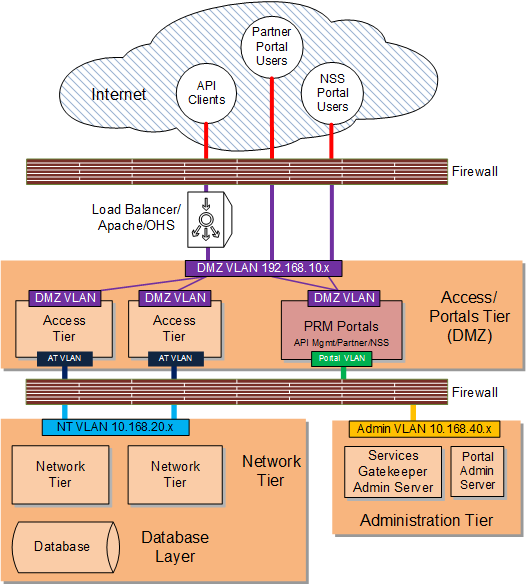
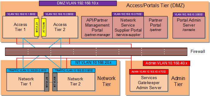
Figure 6-1, Figure 6-2, and Figure 6-3 are only intended to show a high level overview of possible Gatekeeper networking configurations. For explicit routing details between Gatekeeper components, see the following sections:Figure 6-1 shows the most exposed Services Gatekeeper components, API clients and Partner Portal Users, outside firewall protection in the Internet, with the traffic being filtered by the firewall before being passed through to the access tier and the PRM portals. The Services Gatekeeper access and portal tiers are deployed in the DMZ behind a firewall as well as a suitable load balancing device. Suitable load balancing devices include the Apache Software Foundation HTTP web server using mod_wl, the F5 Networks 5 load balancer, or the Oracle HTTP Web Server using mod_wl_ohs. Oracle recommends that you obtain and install a component with proxy capability to limit traffic between the firewall and the Services Gatekeeper Access Tier/Portal Tier.
See "Securing Services Gatekeeper Components in the DMZ" for the list of tasks required to implement this deployment.
If your deployment requires an additional layer of protection, Figure 6-2 shows the administration server isolated in its own network behind the firewall.
See "Securing Services Gatekeeper Components in the DMZ" for the list of tasks required to implement this deployment.
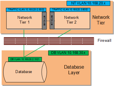
Figure 6-1 shows the network tier behind both firewalls, and freely accessing the database through a JDBC connection. Figure 6-2 shows an additional layer of protection the database layer can be located behind its own firewall.
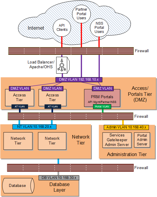
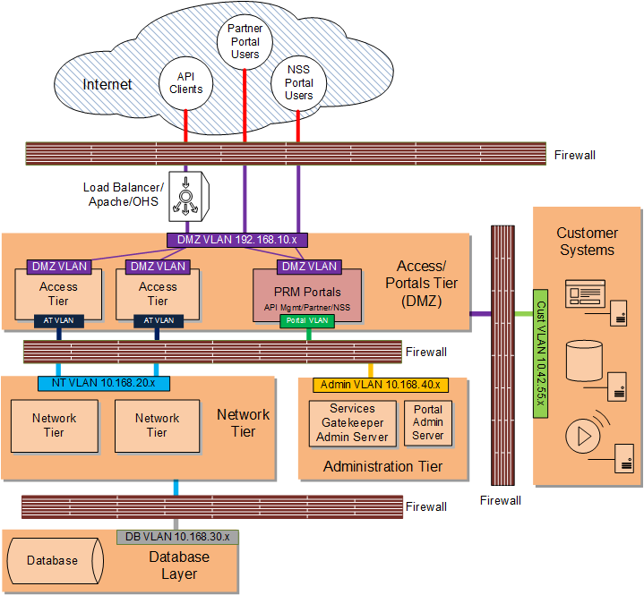
Figure 6-3 shows a Services Gatekeeper DMZ deployment with an isolated administration server, a fire-walled database layer, and an additional firewall separating customer systems such as database servers, media servers, and others. In this deployment, the customer systems are on a separate private sub net behind a firewall which can only connect to the Services Gatekeeper access tier. For an additional layer of protection, use a VPN tunnel as an access gateway to the customer systems as well (not pictured).
See "Securing Services Gatekeeper Components in the DMZ" for the list of tasks required to implement this deployment.
Securing Services Gatekeeper Components in the DMZ
This section includes instructions for configuring specific Services Gatekeeper components for a DMZ configuration:
Complete these tasks to implement a DMZ deployment as shown in Figure 6-1 and Figure 6-2:
Complete all of the tasks in this section and add a firewall between your customer systems and the Services Gatekeeper to implement a DMZ deployment as shown in Figure 6-3.
Securing Traffic Between the Internet and the Access Tier
You secure traffic between the Internet and access tier by:
-
Configuring servers in your access/portal tiers to use non-default ports as well as HTTPS, and certificates if required. See "Encrypting RMI Traffic Between the Access Tier and the Network Tier" for details.
-
Hardening the underlying operating system components as explained in this section.
The following sections have details.
Configuring a Firewall to Protect the Access and Portal Tiers
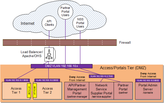
Configure a firewall as explained in the example in Table 6-1. This example uses the sample components and IP addresses/ports shown in Figure 6-2. Yours will be different.
Table 6-1 Configuring a Firewall Between the Internet and the Access/Portals Tiers
| Specifically Allow Traffic From: | To The Component/IP Address:Port | Notes |
|---|---|---|
|
API Clients |
AT1 (192.168.10.1:8002) |
Allow Internet API call traffic to the Access Tier. |
|
API Clients |
AT2 (192.168.10.2:8002) |
Allow Internet API call traffic to the Access Tier. |
|
Portal Admin Server |
N/A |
Disallow Internet traffic to the Portal Admin Server (https://192.168.10.3:8002/console). |
|
API/Partner Management Portal |
N/A |
Disallow Internet traffic to the API/Partner Management Portal (https://192.168.10.3:7002/portal/partner-manager). |
|
Partner Portal Users |
PRM Portals/Portal Administration Server (192.168.10.3:8002) |
Allow Internet traffic to the Partner Portal (https://192.168.10.3:8002/portal/partner). |
|
Network Service Supplier Portal Users |
PRM Portals/Portal Administration Server (192.168.10.3:8002) |
Allow Internet traffic to the Network Service Supplier Portal (https://192.168.10.3:8002/portal/service-supplier). |
Figure 6-4 illustrates the configuration in Table 6-1.
Hardening the Operating System
Keep these operating system level security considerations in mind:
-
Confirm that the Services Gatekeeper binaries are owned by the Services Gatekeeper installation user.
Note:
File permissions and ownership are set correctly by the Services Gatekeeper installer, but you should verify that they have not been modified before deployment. -
Lock down access to everything except:
-
Read/write access to the file system below the WebLogic domain directory
-
Access to the Java Virtual Machine (JVM)
-
Access to the RMI, and HTTP/HTTPS ports (the default SSL ports are 8002 for the access and network tiers, and 7002 for the administration tier).
-
-
Periodically audit the operating system file system file to notify administrators of unauthorized system binary changes.
File system hardening and auditing procedures will differ depending upon your operating system. See the following sections for information on popular Services Gatekeeper options.
Hardening Oracle Linux 6
For detailed hardening instructions pertinent to Oracle Linux 6, see the following sections in the Oracle Linux Security Guide:
-
Pre-Installation Tasks which includes information on physical security, BIOS passwords and other system level considerations.
-
Installing Oracle Linux which includes information on configuring shadow passwords and hashing, disk partition encryption, software selection and network time services.
-
Implementing Oracle Linux Security which includes information on topics including:
Securing Traffic Between the Access and Portal Tiers
You secure the Access and Portal tiers by configuring a firewall between the Internet and the Access and Portal Tiers. See "Configuring a Firewall to Protect the Access and Portal Tiers" for details. The API and Partner Management Portal is not connected to the public Internet, so you do not need to configure traffic through the Internet load balancer/firewall for it. Configuring this firewall protects the Partner Portal and Network Service Supplier Portal traffic.
Encrypting RMI Traffic Between the Access Tier and the Network Tier
To encrypt RMI traffic between the access tier and the network tier for each server in each tier:
-
Open the Administration Console for your domain.
-
Click the Lock & Edit button.
-
Expand the Environments node in the Domain Structure pane and click the Servers node.
-
Click the Configuration tab in the Summary of Servers pane and click the name of the server in the Servers table that you want to configure.
-
Check SSL Listen Port Enabled.
Note:
Weblogic server uses the default JKS file store (Demo Identity and Demo Trust) for SSL configuration. However, you could specify a custom trust Keystore. See the Oracle WebLogic Server 12c: Configuring Managed Servers document for details. -
Enter a numeric port number in the SSL Listen Port edit box.
-
Click Save to save your configuration changes.
-
Expand the Environments node in the Domain Structure pane if it is not already expanded and click Clusters.
-
Click the AT cluster and then click the General tab.
-
Replace the port in the Cluster Address edit box with the SSL port you configured in step 6.
-
Click the Configuration tab, then the Replication tab.
-
Check Secure Replication Enabled.
-
Repeat steps 9 through 12 for the remaining AT and NT servers.
-
Click Save to save your configuration changes.
-
Click Activate Changes to apply your changes to the engine servers.
-
To enable a secure channel for Java Message Service (JMS) add the -Dweblogic.DefaultProtocol=t3s flag to JAVA_OPTIONS in the middleware_home/bin/setDomainEnv.sh script:
JAVA_OPTIONS="${JAVA_OPTIONS} -Dweblogic.DefaultProtocol=t3s" export JAVA_OPTIONS -
Change the ADMIN_URL item in the domain_home/bin/startManagedWeblogic.sh script to https://IP_address:port_number
-
Restart each AT and NT servers with this command:
startManagedManaged.sh server_name https://IP_address:port_number
Note:
Make sure you enable SSL on your administration server as well to ensure that SSL is used throughout the cluster. For more information, see "Securing Services Gatekeeper" in Oracle Communications Services Gatekeeper System Administrator's Guide.Network traffic between the access tier and network tier is now encrypted.
Note:
Keep the following points in mind:-
Services Gatekeeper multiplexes RMI and HTTP through the same port. If you set that port to require encryption, the browser either encrypts the traffic automatically, or returns an error if this is not possible.
-
While it is possible to have both SSL and non-SSL ports configured at the same time, it is recommended that you disable the non-SSL ports.
-
Once RMI encryption is enabled you can no longer use the Platform Test Environment (PTE) to manage Services Gatekeeper. You can, however, use the PTE to test APIs.
Securing Traffic between the Access Tier and the Network Tier
To secure traffic between the access tier and the network tier:
-
Obtain and configure a firewall between the access tier and network tier so that it allows only:
-
RMI traffic between the ATs and NTs (you control the NT using RMI)
-
(As Needed) JMS traffic between the ATs and NTs (for creating and communicating EDRs)
-
HTTP/HTTPS traffic from the Partner Portal
See Table 6-2 for an example based the example components shown in Figure 6-2, and your firewall documentation for installation and configuration instructions.
-
-
Specifying that traffic between the NTs and ATs in your implementation required SSL communication. You did by following the instructions in "Encrypting RMI Traffic Between the Access Tier and the Network Tier".
Configuring a Firewall Between the ATs/Portals and the NTs
This example uses the sample components and IP addresses/ports shown in Figure 6-2. Yours will be different.
Table 6-2 Configuring a Firewall Between the Internet and the Access/Portals Tiers
| Specifically Allow Traffic From: | To The Component/IP Address:Port |
|---|---|
|
Access Tier1 |
Network Tier1 (10.168.20.2:8002) |
|
Access Tier1 |
Network Tier2 (10.168.20.3:8002) |
|
Access Tier2 |
Network Tier1 (10.168.20.2:8002) |
|
Access Tier2 |
Network Tier2 (10.168.20.3:8002) |
|
Access Tier1 |
Services Gatekeeper Administration Server (10.168.40.4:7002) |
|
Access Tier2 |
Services Gatekeeper Administration Server (10.168.40.4:7002) |
|
Network Tier1 |
Services Gatekeeper Administration Server (10.168.40.4:7002) |
|
Network Tier2 |
Services Gatekeeper Administration Server (10.168.40.4:7002) |
Figure 6-5 illustrates the configuration in Table 6-3.
Securing the Services Gatekeeper Administration Server
Securing the administration server involves these tasks:
-
Configuring the Services Gatekeeper administration server to use a nonstandard port so that you can use customized firewall rules as well as encryption (HTTPS, IIOPS, or T3S)
-
Changing the administration server context path from the default of /console to something else. For example: /adminportal.
-
Configuring Services Gatekeeper to only allow SSL traffic to the administration server. See "Restricting Administration Server to SSL" for details.
Restricting Administration Server to SSL
To configure administration server to only allow SSL:
-
Open the Administration Console for your domain.
-
Click Lock & Edit.
-
Expand the Environments node in the Domain Structure pane and click the Servers node.
-
Click AdminServer(Admin).
-
Click Configuration in the Summary of Servers pane and click the name of the server in the Servers table to configure.
-
Click General.
-
Check SSL Listen Port Enabled.
Note:
Weblogic server uses the default JKS file store (Demo Identity and Demo Trust) for SSL configuration. However, you should specify a custom trust Keystore. See the Oracle WebLogic Server 12c: Configuring Managed Servers document for details. -
Enter a numeric port number in the SSL Listen Port edit box.
-
Uncheck the Listen Port Enabled box.
-
Click Save.
-
Click Activate Changes to apply your changes to the engine servers.
Securing the Database
Configure a database between your Network Tier/Administration Server. See your firewall documentation for details. Table 6-3 has example instructions based on the sample components and their IP addresses:ports shown in Figure 6-2. Your components and IP addresses will be different.
Table 6-3 Configuring a Firewall Between NTs and the Database
| Specifically Allow Traffic From: | To The Component/IP Address:Port |
|---|---|
|
Network Tier1 |
Database (10.168.30.2:1521) |
|
Network Tier2 |
Database (10.168.30.2:1521) |
Figure 6-6 illustrates the configuration in Table 6-3.
Securing OBIEE in Services Gatekeeper
Services Gatekeeper uses Oracle Business Intelligence Enterprise Edition (OBIEE) to generate statistics and to create reports about API usage. The OBIEE components deployed in Services Gatekeeper are located in the network tier and are subject to the same protections from firewalls and operating system hardening.
Partner statistics and reports are protected by username/passwords, so partners only have access to their own statistics and reports.
For general information on securing OBIEE, see Fusion Middleware Security Guide for Oracle Business Intelligence Enterprise Edition at the Oracle documentation website:
Securing Node Manager Access to Services Gatekeeper
You can control Services Gatekeeper by using Oracle WebLogic Node Manager (Node Manager) features. Node Manager relies on a one-way SSL connection for security. See ”Configuring Java-based Node Manager Security” and ”Using SSL with Java-Based Node Manager” in Fusion Middleware Node Manager Administrator's Guide for Oracle WebLogic Server 12c for details.
Configuring Connection Filters Instead of a Firewalls
In cases where Services Gatekeeper components are not separated by firewalls, for instance between the network tier and the database layer, you can use WebLogic connection filters to provide network layer access control and block unwanted intrusions.
To configure a WebLogic connection filter:
-
Set your Services Gatekeeper environment:
cd ~/domain_home/bin
. ./setDomainEnv.sh
where domain_home is the path to the domain's home directory.
-
Start WLST:
java weblogic.WLST
-
Connect to the server using the username and password you configured during installation:
connect('username','password','t3://myserver:port_number') -
Switch to the domain security MBean:
cd('/SecurityConfiguration/'+domainName) -
Enable a connection filter:
cmo.setConnectionLoggerEnabled(true)
-
Define the connection filter implementation:
cmo.setConnectionFilter('weblogic.security.net.ConnectionFilterImpl')Note:
The example above uses the default connection filter implementation. For information on creating custom connection filters see "Developing Custom Filters" in Fusion Middleware Programming Security for Oracle WebLogic Server. -
Configure the rules as a string array:
set('ConnectionFilterRules',jarray.array
([String('myserver ip_address port allow t3s https'),
String('ip_address/subnet_mask ip_address port allow'),
String('ip_address ip_address port deny t3 http')],
String))