70 Classic Messaging Server and Tiered Storage Overview
This chapter describes the operation of the Oracle Communications Messaging Server classic message store, its performance characteristics, and how to plan for and allocate store partitions. Additionally, this document describes next generation best practices to meet the storage needs of both ISPs and enterprises.
Overview of Messaging Server Storage
For traditional ISPs that provide web-based email services, the rules of engagement have changed. Thanks to companies such as Google, which can now offer consumers multiple gigabytes of email storage space with unlimited retention, the threat is clear: ISPs, with their much smaller storage allotments (50-100 Mbytes) and automatic purging of messages older than 90 days, need to stay competitive by providing storage and retention capabilities similar to Google, or lose out.
The rules have also changed for enterprises and the corporate messaging market, which are being forced to comply with new regulations requiring email retention for ever longer periods of time. In fact, some companies are faced with the requirement of saving every incoming and outgoing email message forever. The storage requirements for such scenarios can be staggering, to say the least.
As if there weren't enough problems already for ISPs and enterprises, email by its nature is a very I/O intensive application where transaction speed is critical to customer satisfaction. In increasing storage capacity, businesses must ensure that email services maintain acceptable performance levels and do so in a cost-effective manner. To stay competitive, businesses understand that they must purchase large numbers of disk drives to satisfy this new appetite for storage space. Purchasing fiber channel drives is typically cost prohibitive, so ISPs and enterprises will be looking to less expensive alternatives, such as Serial Advanced Technology Attachment (SATA) drives. The challenge with SATA is that in order to reduce cost and provide higher capacity, performance is sacrificed. And there's the dilemma: both ISPs and enterprises need to dramatically increase their email storage capacity while at the same time maintaining acceptable performance levels without "breaking the bank." Customers are under immense legal and financial pressure to find a solution to this problem. The good news is that Oracle can deliver an excellent storage solution for Messaging Server deployments in the form of the Sun StorageTek 6540 Array.
The Messaging Server message store is one of the highest IOPs applications that exists. In the past, customers have kept all portions of the message store on their highest performing, most expensive disks. Fortunately, you can distributed the message store components onto different performing disks to create a cost-effective but high performing application.
Care must be taken to keep the highest IOP portion of the message store (the database and its store partition indexes) on high performance disks. The message store can generate up to 15+ IOPS per message delivered, typically many small, random writes, and is extremely sensitive to response times. If response time diminishes, it can have a cascading effect through the application. Because of the high IOP needs, the message store is ideal for Oracle's StorageTek 6540 controller.
Message Store and ZFS
Oracle's Communications Suite Deployment Engineering group has performed extensive testing with ZFS and measured its impact on the message store. The Messaging Group believes that in the future most Messaging Server customers will be using the ZFS file system. ZFS changes the workload characteristics on the file system, so that there are fewer I/Os, but the I/Os are bigger. ZFS enables read rates to diminish somewhat, whereas it enables write rates to diminish much more. In addition, ZFS can perform snapshotting and compression, which enhances the ability to back up the application. ZFS is also now supported by Oracle Solaris Cluster software.
How the Message Store Works
The message store is a dedicated data store for the delivery, retrieval, and manipulation of Internet mail messages. The message store works with the IMAP4 and POP3 client access servers to provide flexible and easy access to messaging. The message store also works through the HTTP server (mshttpd) to provide messaging capabilities to Convergence clients in a web browser. The message store is organized as a set of folders or user mailboxes. The folder or mailbox is a container for messages. Each user has an INBOX where new mail arrives.
Each IMAP or Webmail user can also have one or more folders where mail can be stored. Folders can contain other folders arranged in a hierarchical tree. Mailboxes owned by an individual user are private folders. Private folders can be shared at the owner's discretion with other users on the same message store. Messaging Server supports sharing folders across multiple stores by using the IMAP protocol. There are two general areas in the message store, one for user files and another for system files. In the user area, the location of each user's INBOX is determined by using a two-level hashing algorithm. Each user mailbox or folder is represented by another directory in its parent folder. Each message is stored as a file. When there are many messages in a folder, the system creates hash directories for that folder. Using hash directories eases the burden on the underlying file system when there are many messages in a folder. In addition to the messages themselves, the message store maintains an index and cache of message header information and other frequently used data to enable clients to rapidly retrieve mailbox information and do common searches without the need to access the individual message files.
A message store can contain many message store partitions for user files. A message store partition is contained by a file system volume. As the file system becomes full, you can create additional file system volumes and message store partitions on those file system volumes to store new users.
Note:
If a message store partition fills up, users on the partition are not able to store additional messages. Address this problem by using one or more of the following approaches:-
Reducing the size of user mailboxes
-
If you are using volume management software, adding additional disks
-
Creating additional partitions and moving mailboxes to the new partitions
The message store maintains only one copy of each message per partition. This is sometimes referred to as a single-copy message store. When the message store receives a message addressed to multiple users or a group or distribution list, it adds a reference to the message in each user's INBOX. Rather than saving a copy of the message in each user's INBOX, the message store avoids the storage of duplicate data. The individual message status flag (seen, read, answered, deleted, and so on) is maintained per folder for each user.
The system area contains information on the entire message store in a database format for faster access and no loss of service. The information in the system area can be reconstructed from the user area. Messaging Server contains a database snapshot function. When needed, you can quickly recover the database to a known state.
Messaging Server also has fast recovery, so that in case of database corruption, you can shut down the message store and bring it back immediately without having to wait for a lengthy database reconstruction.
Messaging Server Disk Throughput
Disk throughput is the amount of data that your system can transfer from memory to disk and from disk to memory. The rate at which this data can be transferred is critical to the performance of Messaging Server. To create efficiencies in your system's disk throughput:
-
Consider your maintenance operations, and ensure you have enough bandwidth for backup. Backup can also affect network bandwidth particularly with remote backups. Private backup networks might be a more efficient alternative.
-
Carefully partition the store and separate store data items (such as tmp and db) to improve throughput efficiency.
-
Ensure the user base is distributed across RAID (Redundant Array of Independent Disks) environments in large deployments
-
Stripe data across multiple disk spindles in order to speed up operations that retrieve data from disk.
-
Allocate enough CPU resources for RAID support, if RAID does not exist on your hardware.
Note:
Measure disk I/O in terms of IOPS (total I/O operations per second) not bandwidth. You need to measure the number of unique disk transactions the system can handle with a very low response time (less than 10 milliseconds).
Typically, most customers deploy their entire message store on the highest performing disk as shown in Figure 70-1.
Figure 70-1 Typical Disk Storage with Message Store
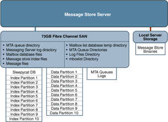
Description of ''Figure 70-1 Typical Disk Storage with Message Store''
Messaging Server Disk Capacity
When planning server system disk space, be sure to include space for operating environment software, Messaging Server software, and message content and tracking. Be sure to use an external disk array if availability is a requirement. For most systems, external disks are required for performance because the internal system disks supply no more than four spindles. For the message store partitions, the storage requirement is the total size of all messages plus 30 percent overhead. In addition, user disk space needs to be allocated. Typically, this space is determined by your site's policy.
Disk Sizing for MTA Message Queues
The purpose of the Messaging Server MTA Queue is to provide a transient store for messages waiting to be delivered. Messages are written to disk in a persistent manner to maintain guaranteed service delivery. If the MTA is unable to deliver the message, it retries delivery. At some point, if delivery is still unsuccessful, the MTA no longer tries to send the message and returns it to the sender.
MTA Message Queue Performance
Sizing the MTA Message Queue disks is an important step for improving MTA performance. The MTA's performance is directly tied to disk I/O above any other system resource. This means that you should plan on a disk volume that consists of multiple disk spindles which are concatenated and striped by using a disk RAID system. End users are quickly affected by the MTA performance. As users press the SEND button on their email client, the MTA does not fully accept receipt of the message until the message has been committed to the MTA Message Queue. Therefore, improved performance on the MTA Message Queue results in better response times for the end-user experience.
MTA Message Queue Availability
SMTP services are considered a guaranteed message delivery service. This is an assurance to end users that the messaging server will not lose messages that the service is attempting to deliver. When you architect the design of the MTA Message Queue system, all effort should be made to ensure that messages will not be lost. This guarantee is usually made by implementing redundant disk systems through various RAID technologies.
MTA Message Queue Available Disk Sizing
The MTA Message Queue grows excessively if one of the following conditions occurs:
-
The site has excessive network connectivity issues
-
The MTA configuration is holding on to messages too long
-
Valid problems are occurring with those messages (not covered in this document)
-
Message stores are operationally down, for example, for maintenance
-
Remote target sites are unavailable or overwhelmed
Performance Considerations for a Message Store Architecture
Message store performance is affected by a variety of factors, including:
-
Disk I/O
-
Inbound message rate (also known as message insertion rate)
-
Message sizes
-
Login rate (POP/IMAP/HTTP)
-
Transaction rate for IMAP and HTTP
-
Concurrent number of connections for the various protocols
-
Network I/O
-
Use of SSL
The preceding factors list the approximate order of impact to the message store. Most performance issues with the Message Storage arise from insufficient disk I/O capacity. Additionally, the way in which you lay out the store on the physical disks can also have a performance impact. For smaller standalone systems, it is possible to use a simple stripe of disks to provide sufficient I/O. For most larger systems, segregate the file system and provide I/O to the various parts of store.
Note:
In a deployment using LMTP, the MTA queue is almost always unused.Messaging Server Directories (General Recommendations for Storage)
Messaging Server uses six directories that receive a significant amount of input and output activity. Because these directories are accessed very frequently, you can increase performance by providing each of those directories with its own disk, or even better, providing each directory with a Redundant Array of Independent Disks (RAID).
The six directories are:
MTA Queue Directory
Recommendation: Can be located on slower disks or on shared NAS
In this directory, many files are created, one for each message that passes through the MTA channels. After the file is sent to the next destination, the file is then deleted. The directory location can be changed by making the queue directory a symlink.
Default location of the MTA Queue directory: /var/opt/sun/comms/messaging/queue
Messaging Server Log Directory
Recommendation: Can be located on slower disks
This directory contains log files which are constantly being appended with new logging information. The number of changes depend on the logging level set. The directory location is controlled by the msconfig option *.logfile.logdir (Unified configuration) or the configutil option logfile.*.logdir (legacy configuration), where * can be a log-generating component such as admin, default, http, imap, or pop. The MTA log files can be changed by making that directory a symlink.
Default location of the Messaging Server log directory: DataRoot/log
Mailbox Database Files
Recommendation: Keep on a fast disk
These files require constant updates as well as cache synchronization. Put this directory on your fastest disk volume. These files are always located in the /var/opt/sun/comms/messaging/store/mboxlist directory.
Message Store Index Files
Recommendation: Keep on fast disk
These files contain meta information about mailboxes, messages, and users. By default, these files are stored with the message files. The msconfig option partition:*.path (Unified configuration) or the configutil option store.partition.*.path (legacy configuration), where * is the name of the partition, controls the directory location. If you have the resources, put these files on your second fastest disk volume.
Default location of the message store index file: /var/opt/sun/comms/messaging/store/partition/primary
Message Files
Recommendation: Can be located on slower disks
These files contain the messages, one file per message. Files are frequently created, never modified, and eventually deleted. By default, they are stored in the same directory as the message store index files. The location can be controlled with the msconfig option partition:partition_name.messagepath (Unified configuration) or the configutil option store.partition.partition_name.messagepath (legacy configuration), where partition_name is the name of the partition. Some deployments might use a single message store partition called primary specified by the store.partition.primary.path. Large sites might have additional partitions that can be specified with store.partition.partition_name.messagepath, where partition_name is the name of the partition.
Default location of the message files: /var/opt/sun/comms/messaging/store/partition/primary
Note:
To separate the message files from the index files (enabling tiered storage), the store.partition.* and .messagepath options are key. These options must be correctly configured to put the message files on a SATA file system when you create the partition.Mailbox List Database Temporary Directory
Recommendation: Can be located on fast disk
This is the directory used by the message store for all temporary files. To maximize performance, this directory should be located on the fastest file system. For Solaris OS, use the msconfig or the configutil options to configure the store.dbtmpdir (same in both Unified configuration and legacy configuration) variable to a directory under tmpfs, for example, /tmp/mboxlist.
Default location of the mailbox list database: /var/opt/sun/comms/messaging/store/mboxlist
The following sections provide more detail on Messaging Server high-access directories.
Additional Information: MTA Queue Directories
In non-LMTP environments, the MTA queue directories in the message store system are also heavily used. LMTP works such that inbound messages are not put in MTA queues but directly inserted into the store. This message insertion lessens the overall I/O requirements of the message store machines and greatly reduces use of the MTA queue directory on message store machines. If the system is standalone or uses the local MTA for Webmail sends, significant I/O can still result on this directory for outbound mail traffic. In a two-tiered environment using LMTP, this directory is lightly used, if at all. In prior releases of Messaging Server, on large systems this directory set needs to be on its own stripe or volume.
MTA queue directories should usually be on their own file systems, separate from the message files in the message store. The message store has a mechanism to stop delivery and appending of messages if the disk space drops below a defined threshold. However, if both the log and queue directories are on the same file system and keep growing, you will run out of disk space and the message store will stop working.
Additional Information: Log Files Directory
The log files directory requires varying amounts of I/O depending on the level of logging that is enabled. The I/O on the logging directory, unlike all of the other high I/O requirements of the message store, is asynchronous. For typical deployment scenarios, do not dedicate an entire LUN for logging. For very large store deployments, or environments where significant logging is required, a dedicated LUN is in order.
Note:
In almost all environments, you need to protect the message store from loss of data. The level of loss and continuous availability that is necessary varies from simple disk protection such as RAID5, to mirroring, to routine backup, to real time replication of data, to a remote data center. Data protection also varies from the need for Automatic System Recovery (ASR) capable machines, to local HA capabilities, to automated remote site failover. These decisions impact the amount of hardware and support staff required to provide service.Additional Information: mboxlist Directory
The mboxlist directory is highly I/O intensive but not very large. The mboxlist directory contains the databases that are used by the stores and their transaction logs. Because of its high I/O activity, and due to the fact that the multiple files that constitute the database cannot be split between different file systems, you should place the mboxlist directory on its own stripe or volume in large deployments. This is also the most likely cause of a loss of vertical scalability, as many procedures of the message store access the databases. For highly active systems, this can be a bottleneck. Bottlenecks in the I/O performance of the mboxlist directory decrease not only the raw performance and response time of the store but also impact the vertical scalability.
For systems with a requirement for fast recovery from backup, place this directory on Solid State Disks (SSD) or a high performance caching array to accept the high write rate that an ongoing restore with a live service will place on the file system. Figure 70-2 depicts this configuration.
Figure 70-2 Next Generation Storage with Message Store
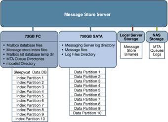
Description of ''Figure 70-2 Next Generation Storage with Message Store''
Multiple Store Partitions
The message store supports multiple store partitions. Place each partition on its own stripe or volume. The number of partitions that should be put on a store is determined by several factors. The obvious factor is the I/O requirements of the peak load on the server. By adding additional file systems as additional store partitions, you increase the available IOPS (total IOs per second) to the server for mail delivery and retrieval. In most environments, you get more IOPS out of a larger number of smaller stripes or LUNs than a small number of larger stripes or LUNs. With some disk arrays, it is possible to configure a set of arrays in two different ways. You can configure each array as a LUN and mount it as a file system. Or, you can configure each array as a LUN and stripe them on the server. Both are valid configurations.
However, multiple store partitions (one per small array or several partitions on a large array striping sets of LUNs into server volumes) are easier to optimize and administer. Raw performance, however, is usually not the overriding factor in deciding how many store partitions you want or need. In corporate environments, it is likely that you need more space than IOPS. Again, it is possible to software stripe across LUNs and provide a single large store partition. However, multiple smaller partitions are generally easier to manage. The overriding factor of determining the appropriate number of store partitions is usually recovery time.
Recovery times for store partitions fall into several categories:
-
First, the fsck command can operate on multiple file systems in parallel on a crash recovery caused by power, hardware, or operating system failure. If you are using a journaling file system (highly recommended and required for any HA platform), this factor is small.
-
Secondly, backup and recovery procedures can be run in parallel across multiple store partitions. This parallelization is limited by the vertical scalability of the mboxlist directory as the message store uses a single set of databases for all of the store partitions. Store cleanup procedures (expire and purge) run in parallel with one thread of execution per store partition.
-
Lastly, mirror or RAID re-sync procedures are faster with smaller LUNs. There are no hard and fast rules here, but the general recommendation in most cases is that a store partition should not encompass more than 10 spindles. The size of drive to use in a storage array is a question of the IOPS requirements versus the space requirements. For most residential ISP POP environments, use "smaller drives." Corporate deployments with large quotas should use "larger" drives. Again, every deployment is different and needs to examine its own set of requirements.
Setting Disk Stripe Width
When setting disk striping, the stripe width should be about the same size as the average message passing through your system. A stripe width of 128 blocks is usually too large and has a negative performance impact. Instead, use values of 8, 16, or 32 blocks (4, 8, or 16 kilobyte message respectively).
MTA Performance Considerations
MTA performance is affected by many factors including, but not limited to:
-
Disk performance
-
Use of SSL
-
The number of messages/connections inbound and outbound
-
The size of messages
-
The number of target destinations/messages
-
The speed and latency of connections to and from the MTA
-
The need to do spam or virus filtering
-
The use of Sieve rules and the need to do other message parsing (like use of the conversion channel)
The MTA is both CPU and I/O intensive. The MTA reads from and writes to two different directories: the queue directory and the logging directory. For a small host (four processors or fewer) functioning as an MTA, you do not need to separate these directories on different file systems. The queue directory is written to synchronously with fairly large writes. The logging directory is a series of smaller asynchronous and sequential writes. On systems that experience high traffic, consider separating these two directories onto two different file systems. In most cases, you will want to plan for redundancy in the MTA in the disk subsystem to avoid permanent loss of mail in the event of a spindle failure. (A spindle failure is by far the single most likely hardware failure.) This implies that either an external disk array or a system with many internal spindles is optimal.
MTA and RAID Trade-offs
There are trade-offs between using external hardware RAID controller devices and using JBOD arrays with software mirroring. The JBOD approach is sometimes less expensive in terms of hardware purchase but always requires more rack space and power. The JBOD approach also marginally decreases server performance, because of the cost of doing the mirroring in software, and usually implies a higher maintenance cost. Software RAID5 has such an impact on performance that it is not a viable alternative. For these reasons, use RAID5 caching controller arrays if RAID5 is preferred.
Background: Communication Services Logical Architectures Overview
You can deploy Communications Services in either a single-tiered or two-tiered logical architecture. Deciding on your logical architecture is crucial, as it determines which machine types you will need, as well as how many. In general, enterprise corporate deployments use a single-tiered architecture while internet service providers (ISPs) and telecommunications deployments use a two-tiered architecture. However, as with all generalities, the exceptions prove the rule. Small ISPs might just as well deploy on a single machine, and larger, centralized enterprises might deploy in a two-tiered architecture for many of the same reasons that ISPs do. As more and more corporations look to offer ease of access to employees working remotely, their deployments will begin to look more and more like an ISP.
Two-tiered Logical Architecture
In a two-tiered logical architecture, the data stores communicate through front-end processes. In the case of Messaging Server, this means MMPs and MTAs are residing on separate machines from the data store processes. A two-tiered architecture enables the mail store to offload important and common tasks and focus on receiving and delivering mail.
There might be some level of cohabitation with other services. For example, you could have the Calendar store and the message store on the same machine. Similarly, you could have the calendar front end on the MMP machine. In a two-tiered logical architecture, Directory Server is usually a complex deployment in its own right, with multi-master and replication to a set of load-balanced consumer directories.
Benefits of a Two-tiered Architecture
All services within the Communications Services offering rely on network capabilities. A two-tiered architecture provides for a network design with two separate networks: the public (user-facing) network, and the private (data center) network. Separating your network into two tiers provides the following benefits:
-
Hides Internal Networks. By separating the public (user-facing) network and the private (data center) network, you provide security by hiding the data center information. This information includes network information, such as IP addresses and host names, as well as user data, such as mailboxes and calendar information.
-
Provides Redundancy of Network Services. By provisioning service access across multiple front-end machines, you create redundancy for the system. By adding redundant messaging front-end servers, you improve service uptime by balancing SMTP requests to the available messaging front-end hosts.
-
Limits Available Data on Access Layer Hosts. Should the access layer hosts be compromised, the attackers cannot get to critical data from the access hosts.
-
Offloads Tasks to the Access Layer. By enabling the access layer to take complete ownership of several tasks, the number of user mailboxes on a message store increases. This is useful because the costs of both purchase and maintenance are much higher for store servers than for access layer machines (the second tier). Access layer machines are usually smaller, do not require large amounts of disk (see "MTA Performance Considerations") and are rarely backed up. A partial list of features that are offloaded by the second tier includes:
-
Denial of service protection
-
SSL
-
Reverse DNS
-
UBE (spam) and virus scanning
-
Initial authentication - Authentications to the message store should always succeed and the directory servers are more likely to have cached the entry recently.
-
LMTP - With support for LMTP between the MTA relays and the message stores, SMTP processing is offloaded and the need to do an additional write of the message into the MTA queues on the message stores is eliminated.
-
-
Simplifies End-user Settings in Client Applications. By using a two-tiered architecture, end users do not have to remember the physical name of hosts that their messaging and calendar applications connect to. The Access-Layer Application hosts provide proxies to connect end users to their assigned messaging or calendar data center host. Services such as IMAP are connected to the back-end service using LDAP information to identify the name of the user's mailbox host. For calendar services, the calendar front-end hosts provide a calendar lookup using the directory server to create a back-end connection to the user's assigned calendar store host.
This capability enables all end users to share the same host names for their client settings. For example, instead of remembering that their message store is host-a, the user simply uses the setting of mail. The MMP provides the proxy service to the user's assigned message store. You need to provide the DNS and load balancing settings to point all incoming connections for mail to one (or more) MMPs.
By placing Messaging Server into two tiers, more than one Messaging Server back-end server can be used.
An additional benefit of this proxy capability provides geographically dispersed users to leverage the same client application settings regardless of their physical location. Should a user from Europe visit California, the user will be able to connect to the immediate access server in California. The user's LDAP information will tell the access server to create a separate connection on the user's behalf to the user's message store located in Europe. Lastly, this enables you to run a large environment without having to configure user browsers differently, simplifying user support. You can move a user's mailbox from one mail store to another without contacting the user or changing the desktop.
-
Reduces Network HTTP Traffic on the Data Center. The Messaging Server front-end greatly reduce HTTP traffic to the data center network. HTTP provides a connectionless service. For each HTML element, a separate HTTP request must be sent to the mail or calendar service. These requests can be for static data, such as an image, style sheets, JavaScript files, or HTML files. By placing these elements closer to the end user, you reduce network traffic on the back-end data center.
Horizontal Scalability Strategy
Scalability is critical to organizations needing to make the most cost-effective use of their computing resources, handle peak workloads, and grow their infrastructure as rapidly as their business grows. Keep these points in mind:
-
How the system responds to increasing workloads: what performance it provides, and as the workload increases, whether it crashes or enables performance to gracefully degrade.
-
How easy it is to add processors, CPUs, storage, and I/O resources to a system or network to serve increasing demands from users.
-
Whether the same environment can support applications as they grow from Low-end systems to mid-range servers and mainframe-class systems.
When deployed in a two-tiered architecture, Messaging Server is meant to scale very effectively in a horizontal manner. Each functional element can support increased load by adding additional machines to a given tier.
Scaling Front-end and Back-end Services
In practice, the method for scaling the front-end and back-end services differs slightly. For Tier 1 elements, you start the scaling process when traffic to the front end grows beyond current capacity. You add relatively low cost machines to the tier and load balance across these machines. Thus, load balancers can precede each of the Tier 1 service functions as overall system load, service distribution, and scalability requirements dictate.
For Tier 2 elements, you start the scaling process when the back-end services have exceeded user or data capacity. As a general rule, design the Tier 2 services to accommodate just under double the load capacity of the Tier 1 services. For example, for an architecture designed for 5,000 users, the Tier 1 front-end services are designed to support 5,000 users. The back-end services are then doubled, and designed to accommodate 10,000 users. If the system capacity exceeds 5,000 users, the front-end services can be horizontally scaled. If the overall capacity reaches 5,000 users, then the back-end services can be scaled to accommodate. Such design enables flexibility for growth, whether the growth is in terms of users or throughput.
Implementing Local Message Transfer Protocol (LMTP) for Messaging Server
Best practices say you should implement LMTP to replace SMTP for message insertion. An LMTP architecture is more efficient for delivering to the back-end message store because:
-
Reduces the load on the stores. Relays are horizontally scalable while stores are not, thus it is a good practice to make the relays perform as much of the processing as possible.
-
It reduces IOPS by as much as 30 percent by removing the MTA queues from the stores.
-
It reduces the load on LDAP servers.
-
The LDAP infrastructure is often the limiting factor in large messaging deployments.
-
It reduces the number of message queues.
-
It requires a small amount of shared/NFS storage across all inbound MTAs.
You need a two-tiered architecture to implement LMTP.
Background: "How Email Works" Introduction to Messaging Server
This write up is a basic introduction. It does avoid most of the more complicated configurations and mechanisms which are part of the Messaging Server. The key objective is to understand "how email works" from a basic "black box" model. As this section progresses, you will start getting the more complicated information on the internals of the Messaging Server.
What Does Messaging Server Enable Users to Do?
The Messaging Server enables users to interact with their email message data in three different manners:
-
Users can write an email, and then send it to someone(s).
-
Users can receive emails from others.
-
Users can access their mailbox.
Figure 70-3 How Messaging Server Allows Users to Interact with Message Data
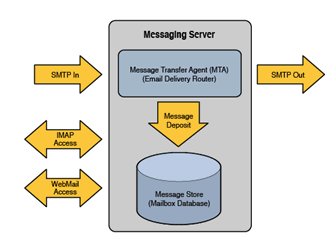
Description of ''Figure 70-3 How Messaging Server Allows Users to Interact with Message Data''
The key components of Messaging Server are:
-
Message Transport Agent (MTA)
-
Message Store Database
-
Message Access Services
-
IMAP/POP3
-
Webmail Access for Convergence (separate product)
Figure 70-3 simplifies the Messaging Server into the following three components:
-
Messages are delivered into the Messaging Server via the MTA. The MTA is the SMTP Server which accepts the email message and then route the message to it's destination. The destination for the email could be either the message store or to another server somewhere out over the network.
-
The message store is an Oracle private database, which stores user's mailboxes and message data.
-
Users access their mailboxes via either IMAP, POP3 or through Webmail.
A User Decides to Send an Email
Users write their emails using any of the popular email clients out on the market. These email clients could include Mozilla/Thunderbird, Apple Mail, Outlook, or any other IMAP-based email application. Once the email is ready, the user would click the "SEND" button.
The "SEND" button allows the email application to connect with the MTA. The client connects to the MTA using the SMTP protocol. Figure 70-4 shows the connection of the user to the Messaging Server MTA.
Figure 70-4 Client Connects to the Messaging Server MTA
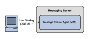
Description of ''Figure 70-4 Client Connects to the Messaging Server MTA''
On the connection to the MTA, the client will send the message over the network to the MTA. The MTA would then store the message in the Message Queue Disk and release the client connection. The message stored on the queue will then be read and the address of the message will be evaluated by using information stored in the Directory Server using LDAP. Figure 70-5 shows the MTA storing the message in the message queue, which is then evaluated by LDAP.
Figure 70-5 MTA Stores Message to Message Queue and Message Evaluated Through LDAP
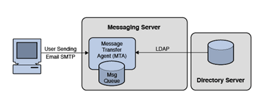
Description of ''Figure 70-5 MTA Stores Message to Message Queue and Message Evaluated Through LDAP''
At this point, the MTA will attempt to deliver the message to one of three places:
-
Into a User's Mailbox
-
Into another Messaging Server
-
Into another site on the Internet (note for security: it is recommend that the MTA forward the message to a "smarthost" MTA to handle the message delivery over the Internet)
It is important to note that once the message is on the Message Disk Queue, and the MTA has responsibility of the message. We guarantee this responsibility by committing the message to disk. It is this commitment which provides the first clue into a our first performance limitation. We write all MTA data to a disk queue, and we therefore are bounded by the disk i/o performance of that disk system. We also need to ensure that the disk system is highly available through RAID. (Typically RAID 0+1 or RAID 5.)
Postal Service Example: An example of this would be a letter that you drop into a postal mailbox. If you drop a letter of at the Post Office, you are assuming that the Postal Service will mail the message to the destination. You will not expect the message to get lost.
The MTA will not remove the message from the Message Disk Queue until a successful delivery. If a delivery attempt fails, it will keep trying. If it fails a final time, the message will be HELD on the disk queue and a notification sent back to the sender. The MTA logs will record the whole history. Figure 70-6 shows how the MTA delivers a message.
Figure 70-6 How the MTA Delivers a Message
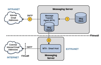
Description of ''Figure 70-6 How the MTA Delivers a Message''
The MTA will attempt to deliver the message in one of three possible ways:
-
Message is Deposited into the User's Mailbox on the message store.
-
Message is Sent to another MTA Server on the Same Local Network.
-
Message is sent to the Internet by first sending to the Smarthost.
The Smarthost MTA sits between the Messaging Server inside the protected network and the Internet. Typically this would be in an area outside the internal network. The Smarthost would evaluate the message address by domain name. Using DNS, the MTA would attempt to identify the DNS MX Record and A Record for the destination of the email. It would then attempt to deliver the message to the host of that IP Address using SMTP.
User Receives an Email
Figure 70-7 shows how a receives email from the MTA.
Figure 70-7 How a User Receives Email from the MTA
Description of ''Figure 70-7 How a User Receives Email from the MTA''
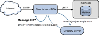
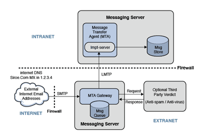
An email sent to a user on the message store. In the case of the message arriving from the Internet, the email sender would address the email to "jon@example.com". The email sender's MTA would look up "example.com" in DNS and find either an MX record or an A record for this site. Figure 70-8 shows the delivery process of an inbound message through the MTA.
The Inbound MTA for the site may be configured to detect SPAM or Viruses. In this case, the message will be sent to a anti-spam/anti-virus verdict engine (such as Cloudmark or Symantec Brightmail). If the email passes, it is evaluated for message routing. The email address is evaluated in the Directory Server. If the email address is valid, it is then sent to the user's mailbox host (mailboxb).
User Access Mailbox
Figure 70-9 shows the process of users accessing their mailboxes.
If users want to access their email, they use their email client. These clients, such as Mozilla Thunderbird or Apple Mail, connect to the mailbox using the IMAP protocol. In some cases, ISPs limit access to POP3 protocol.
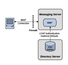
The email client would connect to Messaging Server's Mail Multiplexor Proxy (MMP). The MMP would accept the user's email credentials (their username and password) and validate their login using the Directory Server. Should the authentication be successful, the MMP would then identify the user's backend message store server. The MMP would then connect to this backend message store on the user's behalf. The user can then access their mailbox data.
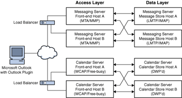
The value of the MMP is that it provides 1) Security and 2) Scalability. Security is improved by the use of the MMP by isolating the message store from the end-users. This helps to prevent unauthorized access (hacking) into the message store server data. Scalability (as seen in the figure below) is improved through Horizontal Scalability. This means that the architecture can grow by adding additional MMPs and backend message store servers. Figure 70-10 shows the capacity growth of the access layer through horizontal scalability.
Figure 70-10 Growing Access Layer Capacity
Description of ''Figure 70-10 Growing Access Layer Capacity''
