2 Using Design Studio to Extend UIM
This chapter provides information on Oracle Communications Design Studio, an Eclipse-based integration development environment. Design Studio comes with features specific to Oracle Communications Unified Inventory Management (UIM) that enable you to extend UIM.
Installing Design Studio
Design Studio is used to extend Oracle products. Different features are available for the different Oracle products, and each feature provides JAR files that are unique to the product.
For directions on how to install Design Studio, see Design Studio Installation Guide. The instructions describe how to install all available Oracle Communications features with a single installation. Of the features installed, UIM requires:
-
Oracle Communications Design Studio Platform
-
Oracle Communications Design Studio Domain Modelling
-
Oracle Communications Design Studio for Inventory
Configuring Design Studio
To do development work in Design Studio, you must configure the Design Studio environment. This requires:
Setting System Variables
After installing Eclipse, you must set system variables to point to the correct version of the JDK.
To set the system variables:
-
From the Windows Start menu, select Control Panel, then select System.
The System Properties window appears.
-
Click the Advanced tab.
-
Click Environment Variables.
The Environment Variables window appears.
-
Define a new system variable named JAVA_HOME:
-
In the System Variables section, click New.
The New System Variables window appears.
-
In the Variable name field, enter JAVA_HOME.
-
In the Variable value field, enter the path to the jdk directory for your installation. For example:
C:/Java/jdkVersionDir/bin
where jdkVersionDir is the supported JDK version directory.
-
Click OK.
For information on the JDK version, see "Software Requirements".
-
-
Update the existing system variable Path:
-
In the System Variables section, select Path, and click Edit.
The Edit System Variables window appears.
-
In the Variable value field, add the path to the bin directory for your jdk installation. This should be added at the beginning of the Path to take precedence on other possible system path values. For example:
C:/Java/jdkVersionDir/bin
where jdkVersionDir is the supported JDK version directory.
-
Click OK.
The Environment Variables window appears.
For information on the JDK version, see "Software Requirements".
-
-
Click OK.
The System Properties window appears.
-
Click OK.
Setting the Compiler Compliance Level
When you install Eclipse, the compiler compliance level is set to a default value. This compliance value must reflect the correct version of the JDK for UIM.
See "Software Requirements" for information on the JDK version.
To set the compiler compliance level in Design Studio:
-
From the menu, select Window, then select Preferences.
The Preferences window appears.
-
In the navigation panel, expand Java, and click Compiler.
-
Verify that the Compiler compliance level is set to the correct Java version.
If it is not, from the Compiler compliance level list, select the correct Java version.
-
Click Apply, then click OK.
Configuring the eclipse.ini File
You must configure the eclipse.ini file to include the -vm run-time option, which is used to locate the Java VM to use to compile projects within Eclipse. If not specified, Eclipse uses a search sequence to locate a suitable VM. If an incorrect VM is used to compile a project, you may encounter issues when deploying the resultant cartridge into UIM.
To configure the eclipse.ini file:
-
Navigate to your Eclipse_Home directory.
-
Open the eclipse.ini file.
-
Add the -vm run-time option and its value (the path to your Java executable) before the -vmargs run-time option.
When adding the -vm option, follow these guidelines:
-
The -vm option and its value (the path) must be on separate lines.
-
The -vm option value must be the full absolute path to the Java executable, not just to the directory that contains the Java executable.
-
The -vm option value cannot contain spaces. If any of the directories in the path to your Java executable contain spaces, you must rename the directories.
-
The -vm option must be placed before the -vmargs option, which is a default option that is present in the eclipse.ini file.
The following are examples; your exact path to the Java executable may be different:
-vm
C:/Java/jdkVersionDir/bin/javaw.exe
Or:
-vm
C:/jdkVersionDir/bin/javaw.exe
where jdkVersionDir is the JDK version directory where you installed Java.
-
-
Save and close the eclipse.ini file.
See "Software Requirements" for information on the JDK version.
Importing the Model Projects
The following model projects must be imported into your workspace before modeling any UIM entities in Design Studio. The successful compilation of an Inventory project is dependent upon the model projects; however, the model projects are not compiled in Design Studio, nor are they deployed into UIM. The model projects are located in the UIM_Home/cartridges/required directory, and are also delivered as part of the UIM SDK. See "About the UIM SDK" for more information.
-
ora_uim_mds
-
ora_uim_model
For instructions on how to import projects into Design Studio, see the Design Studio Help.
Note:
The model projects are installed with UIM. As a result, the model projects may change with each new UIM patchset or maintenance release. Contact your System Administrator to get the latest version of the model projects.Configuring the Project Library List
Depending on the contents of your project, you may or may not need to configure the project library list. For example, if you are extending a UIM class, the project library list must be configured to point to the location of the UIM JAR file that contains the UIM class you are extending. In this example, the UIM JAR file is required to compile the project. The UIM JAR files, and other files, are provided in the UIM Software Developer's Kit (UIM SDK). See "About the UIM SDK" for more information, including a listing of the UIM SDK contents, and instructions on how to build an Inventory project using the UIM SDK.
Imported projects include a library list of the files needed to compile the project, and the project library list must be configured to point to a location to pick up the cited files.
For instructions on how to configure the project library list, see the Design Studio Help.
Note:
Project library lists include JAR files that are installed with UIM. As a result, these JAR files may change with each new UIM patchset or maintenance release. Contact your System Administrator to get the latest version of these JAR files.About Design Studio Perspectives
Perspectives define your Workbench layout and provide different functionality for working with different types of resources. Several perspectives are available within Design Studio.
When extending UIM, commonly used perspectives include:
-
Java
-
Studio Design
-
Studio Environment
For instructions on how to open a perspective, see the Design Studio Help.
About Design Studio Views
Within a given perspective, views further define your Workbench layout and provide different presentations of resources. Several views are available within Design Studio, and the available views are dependent upon the perspective.
When extending UIM, commonly used views include:
-
Java perspective views:
-
Ant
-
Navigator
-
Package Explorer
-
Problems
-
-
Studio Design perspective views:
-
Cartridge
-
Package Explorer
-
Problems
-
-
Studio Environment perspective views:
-
Cartridge Management
-
Environment
-
Problems
-
For instructions on how to open a view, see the Design Studio Help.
About Cartridges and Cartridge Packs
A cartridge is collection of entity specifications, characteristics, rulesets, and extended code defined in Design Studio. Cartridges are built in Design Studio from projects. When a project is compiled, the result is a JAR file (the cartridge) that you can deploy into UIM. The name you choose for the project becomes the name of the cartridge, and everything you create within that project is automatically part of the cartridge.
A cartridge pack is one or more cartridges that collectively address a particular business need or technology. Oracle offers cartridge packs that extend UIM for a particular technology, such as Cable TV or GSM 3GPP. Cartridge packs can also be created by customers and third parties. Cartridge packs can be deployed as downloaded, or they can be imported into Design Studio and extended before deployment.
You can create your own custom cartridges to extend UIM and to organize the extensions. For example, you could create a cartridge that contains all characteristics, another that contains all specifications, and so forth. Or you could create one cartridge per business area, such as telephone numbers or equipment, where each cartridge contains characteristics, specifications, and so forth, that are specific to the business area.
See UIM Cartridge Guide for additional information.
Working with Cartridges in Design Studio
This section includes a brief overview of how you work with projects and cartridges in Design Studio. For more information see Design Studio Help.
Working With Cartridge Dependencies
A cartridge can be dependent on other cartridges. These dependencies are specified on the Project editor Dependency tab. For example, all Inventory cartridges are dependent upon the ora_uim_model project. So, when you create a new Inventory project, the Dependency tab automatically includes ora_uim_model in the list of project names. Projects that are listed on the Dependency tab indicate that the project can be referenced by the Inventory project at design time.
The projects listed on the Dependency tab do not indicate project compilation dependencies, which simply require that dependent projects be present in the workspace. For example, to compile an Inventory project, both the ora_uim_model and ora_uim_mds projects must be present in your workspace. However, only the ora_uim_model project is listed on the Dependency tab. The ora_uim_mds project is not listed on the Dependency tab because designing the Inventory project content is not dependent upon referencing anything in the ora_uim_mds project; but, the ora_uim_mds project must be present in the workspace to compile run-time artifacts that are used by the UIM UI.
You can define additional cartridge dependencies on the Project editor Dependency tab, and specify the order of compilation by moving the project names up or down within the list. For instructions on how to define cartridge dependencies, see the Design Studio Help.
About Imported Cartridge Packs
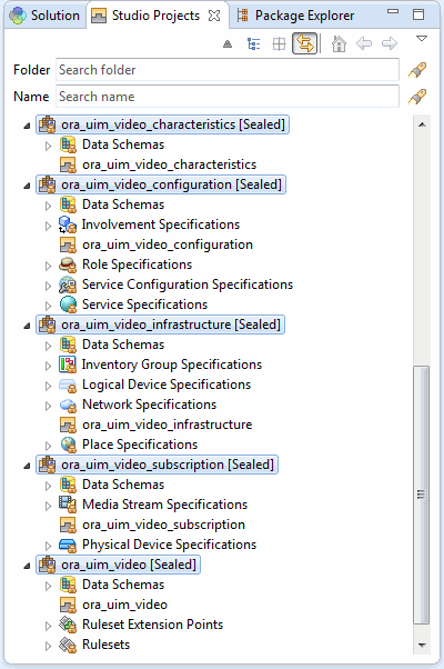
When you import a cartridge pack into Design Studio, its contents are sealed, meaning that you cannot modify them. Figure 2-1 shows the Studio Design perspective Studio Projects view of the imported projects from the Cable TV cartridge pack.
Imported projects include a library list of the files needed to compile the project, and the project library list must be configured to point to a location to pick up the cited files. See "Configuring the Project Library List" for more information.
For instructions on how to import a cartridge pack into Design Studio, see the Design Studio Help.
Viewing Cartridges in Design Studio
There are several ways to view the content of cartridges in Design Studio.
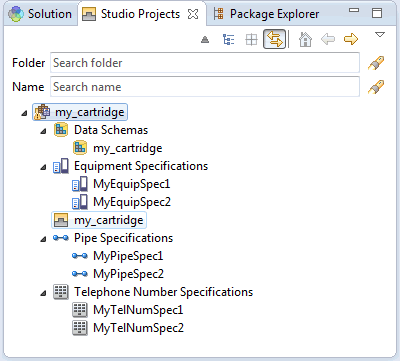
Figure 2-2 shows a cartridge project called my_cartridge as it appears in the Studio Projects view. The corresponding Inventory Project editor is also shown.
Figure 2-2 Studio Projects View of a Project
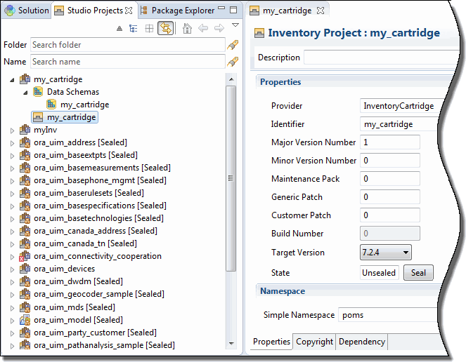
Description of ''Figure 2-2 Studio Projects View of a Project''
By expanding the cartridge in the Studio Projects view, you can see the contents created with each cartridge.
By switching to the Package Explorer view and expanding the cartridge, you can see the file types of the contents created with each cartridge. Figure 2-3 shows my_cartridge as it appears in the Package Explorer view. The resultant JAR file resides in the cartridgeBin directory. The corresponding Inventory Project editor is also shown.
Figure 2-3 Package Explorer View of Inventory Cartridge
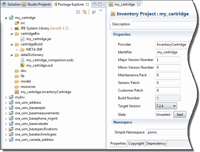
Description of ''Figure 2-3 Package Explorer View of Inventory Cartridge''
The Package Explorer view shows four files named my_cartridge. They are:
-
my_cartridge: The Studio Inventory project.
-
my_cartridge.jar: The JAR file that is deployed into UIM.
-
my_cartridge.xsd and my_cartridge_companion.xsdc: Design Studio core files that are used to store characteristics as data elements within a schema entity (data dictionary).
-
my_cartridge.inventoryCartridge: The Inventory Project editor, shown on the right side of Figure 2-3.
The cartridgeBin and cartridgeBuild directories do not exist until you build the project, which also creates the my_cartridge.jar file.
How Content Is Displayed
The specifications and other content of a project are grouped based on type in the Studio Projects view of the Studio Design perspective. For example, when an Equipment specification is created, it is grouped under Equipment Specifications. When a Pipe specification is created, it is grouped under Pipe Specifications.
These groupings are purely organizational; they do not represent physical directories. Figure 2-4 shows cartridge content that includes six entities created from three different specifications.
About Building Cartridges
When building cartridges in Design Studio, it is important that you configure your environment correctly to avoid errors later in the process.
See "Configuring Design Studio" for more information.
About Deploying Cartridges and Cartridge Packs
You can deploy cartridges and cartridge packs into UIM using the following methods:
-
Deploy directly from Design Studio.
You can deploy cartridges and cartridge packs interactively from Design Studio to test environments. Design Studio enables you to manage cartridges in the test environment consistently, manage common test environment connection parameters across the design team, and compare cartridge version and build numbers in the development environment with those of the cartridges deployed in the test environment. See the Design Studio Help for more information.
-
Deploy using the Design Studio Cartridge Management Tool.
The Cartridge Management Tool (CMT) enables you to automate cartridge deployment. You can use the CMT to deploy cartridges into both test and production environments. See the Design Studio Developer's Guide for more information.
-
Deploy using the UIM Cartridge Deployer Tool.
The UIM Cartridge Deployer Tool (CDT) is a GUI-based tool that enables you to deploy to UIM run-time environments. The Oracle Universal Installer installs the CDT as part of the UIM installation process. See the UIM Cartridge Guide for more information.
See "Troubleshooting Cartridge Deployment" for information on working around possible cartridge deployment issues.
About Cartridge Upgrades
Cartridges can be upgraded. For example, the cartridges in a cartridge pack might be upgraded for a new release. The upgrade process occurs in Design Studio and begins automatically when you open a cartridge that was built in a previous release.
When upgrading a cartridge that is dependent on another cartridge, you must upgrade the dependent cartridge first. During the upgrade process, all dependent cartridges must exist in the workspace to ensure that the upgrade process can convert all cartridges in the correct order.
For instructions on how to upgrade a cartridge, see the Design Studio Help.
About the UIM SDK
The UIM Software Developer's Kit (UIM SDK) provides the resources required to build an Inventory cartridge in Design Studio.
Any custom code that extends UIM can be written in Design Studio by creating an Inventory cartridge and adding custom Java code to the cartridge. In the Java perspective Package Explorer view, you can create package structures and Java source files as needed. Depending on what your custom code references, you may need the SDK to successfully build your Inventory cartridge. For example, you need the SDK if you do one of the following tasks:
-
Call a UIM API Entity Manager method.
-
Use the utility methods provided in the ora_uim_common cartridge.
-
Build a new UIM web service.
-
Install the TOSCA Parser (an OpenStack project) for use with Network Service Orchestration.
-
Use the metadata files that define the UIM data model.
This section describes the UIM SDK contents and provides instructions for setting up your Design Studio workspace to include the UIM SDK-provided resources required to build an Inventory cartridge.
Note:
Compiled code becomes part of the Inventory cartridge JAR file that can be deployed into UIM. See "About Deploying Cartridges and Cartridge Packs" for more information.UIM SDK Contents
The UIM SDK contains the directories, subdirectories, and artifacts for the support of Design Studio cartridges. Figure 2-5 shows the following contents:
-
UIM_SDK/cartridges directory and its following subdirectories
-
base: Contains the UIM base cartridges.
-
required: Contains the UIM required cartridges for any inventory cartridge.
-
sample: Contains some sample cartridges.
-
tools.studioProjects: Contains the ora_uim_entity_sdk cartridge ZIP file. See "About the Metadata Files" for more information about this cartridge.
-
-
UIM_SDK/lib directory with the list of UIM libraries. See Figure 2-6 for the file content list.
-
UIM_SDK/NSO tools directory and subdirectory containing artifacts for Network Service Orchestration support.
-
ToscaTranslator: Contains the Python setup files for Tosca parser support.
-
-
UIM_SDK/webservices directory containing cartridge project ZIP files that you import into Design Studio.
For more details on the contents of the UIM_SDK/webservices directory and the UIM Reference Web Service, see UIM Web Services Developer's Guide.
For more information on the Network Service Orchestration RESTful API resources, refer to Network Service Orchestration Implementation Guide.
Figure 2-5 shows contents of the UIM_SDK directory.
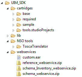
Figure 2-6 shows the UIM_SDK/lib directory, which contains UIM JAR files that you use to configure your project library list in Design Studio.
Figure 2-6 UIM SDK lib Directory Contents
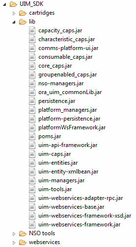
Description of ''Figure 2-6 UIM SDK lib Directory Contents''
See "Building an Inventory Cartridge Using the UIM SDK" for instructions on importing the ZIP files into Design Studio, and configuring your project library list with the JAR files in Design Studio.
Building an Inventory Cartridge Using the UIM SDK
This section assumes you have already installed the following software for use with the UIM SDK for UIM:
-
Design Studio
If not, see Design Studio Installation Guide for information on installing Design Studio.
-
JDK (with the latest critical patch)
If not, see UIM Installation Guide for information on installing the JDK.
To build an Inventory cartridge using the UIM SDK:
-
Create a local directory, such as UIM_SDK_Home.
-
From the Oracle Software Delivery Cloud, download the UIM SDK into the UIM_SDK_Home local directory.
-
Open the downloaded UIM_SDK.zip file and extract the contents into the UIM_SDK_Home local directory.
-
Create another local directory named OTHER_LIB.
-
Copy the following WebLogic libraries from your WebLogic Server installation into the OTHER_LIB local directory:
-
WL_Home/oracle_common/modules/javax.ejb_version.jar
-
WL_Home/oracle_common/modules/javax.jms_version.jar
-
WL_Home/oracle_common/modules/javax.persistence_version.jar
-
WL_Home/oracle_common/modules / jersey-core-version.jar
-
WL_Home/wlserver/modules/com.bea.core.xml.xmlbeans_version.jar
-
WL_Home/wlserver/modules/javax.transaction_version.jar
-
WL_Home/wlserver/server/lib/weblogic.jar
-
WL_Home/wlserver/server/lib/wlclient.jar
-
WL_Home/wlserver/server/lib/wsee-client-ext.jar
-
WL_Home/wlserver/modules/com.bea.core.xml.beaxmlbeans_version.jar
where
-
WL_Home is the WebLogic Server installation home directory.
-
version is the version number in each filename located in the WebLogic Server installation.
See "Software Requirements" for version information on the WebLogic Server installation.
-
-
Copy the log4j-version.jar file into the OTHER_LIB local directory where version is the recommended log4j version.
Note:
If you do not have this file, go to the following website:http://archive.apache.org/dist/logging/log4jSelect the appropriate software version directory. Download the apache-log4j-version.zip file and extract the log4j-version.jar file into the OTHER_LIB local directory.
See "Software Requirements" for version information on log4j utility.
-
Open Design Studio.
-
Configure your Design Studio environment for development work. See "Configuring Design Studio" for more information.
-
Open a new workspace.
-
Import the required cartridges into your workspace from the UIM_SDK_Home/UIM_SDK/cartridges/required directory.
Note:
See the Design Studio Help for information on how to import projects using archive files related to steps 10-14. -
Import any needed base cartridges into your workspace from the UIM_SDK_Home/UIM_SDK/cartridges/base directory.
-
Import any needed sample cartridges into your workspace from the UIM_SDK_Home/UIM_SDK/cartridges/sample directory.
-
Import any needed tools into your workspace from the UIM_SDK_Home/UIM_SDK/cartridges/tools directory.
-
Import any needed web service cartridges into your workspace from the UIM_SDK_Home/UIM_SDK/webservices directory.
-
Create a new Inventory project.
See the Design Studio Help for information on creating new cartridge projects.
-
Configure the Inventory project library list with the UIM libraries:
-
Select the Inventory project.
-
From the project menu, select Properties.
-
Select Java Build Path.
-
Click the Libraries tab.
-
Click Add Variable.
The New Variable Classpath Entry dialog box appears.
-
Click Configure Variables.
The Preferences dialog box appears.
-
Click New.
The New Variable Entry dialog box appears.
-
In the Name field, enter UIM_LIB.
-
Click Folder, and browse to and select UIM_SDK_Home/UIM_SDK/lib.
-
Click OK.
The Preferences dialog box appears.
-
Click OK.
The New Variable Classpath Entry dialog box appears.
-
Select UIM_LIB.
-
Click Extend.
The Variable Extension dialog box appears.
-
Select all libraries.
-
Click OK.
The Inventory project Java Build Path dialog box appears with the selected libraries added.
-
Click OK.
-
-
Configure the Inventory project library list with the other libraries from WebLogic and Log4j. To do so, repeat step 16, but:
-
Build the Inventory project.
After you successfully build the project, add any custom artifacts and rebuild the project.
About the Developer-Facing Inventory Menu Options
From the Studio menu, select New, then select Inventory, then select Administration to see the developer-facing options that are available in Design Studio with the installation of the Inventory feature. The options are:
-
Sequence Specification
-
Extension Point
-
Enabled Extension Point
-
Ruleset
-
Ruleset Extension
-
Ruleset Extension - Global
-
Inventory Group Specification
The Sequence Specification option is described in the following sections. The remaining developer-facing options, with the exception of Inventory Group Specification, are described in Chapter 8, "Extending UIM Through Rulesets". For information on Inventory Group Specification, see UIM Concepts and the Design Studio Help.
Understanding the Sequence Specification
A sequence is a unique, generated number that is used as an identifier. Sequences can be used alone, or concatenated with other attributes to create a larger identifier, such as a connection ID. For example, in the following connection ID, a sequence can be generated to represent the facility designator in bold: 101/T1/PLANTXXAK01/IRVGTXXAK1.
The Sequence specification defines criteria for a sequence. Figure 2-7 shows the Sequence Specification editor Properties tab where the criteria of Minimum Value, Maximum Value, and Increment Value are defined.
For instructions on how to create a Sequence Specification, see the Design Studio Help.
Figure 2-7 Sequence Specification Editor
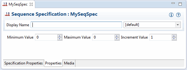
Description of ''Figure 2-7 Sequence Specification Editor''
The Sequence specification can be used:
-
In custom code to set an identifier
-
With the Entity Identifier specification to set the entity identifier
Using the Sequence Specification in Custom Code
UIM provides the SequenceGenerator interface, which is a mechanism for generating sequences. The interface exposes methods that generate three types of sequences:
A global sequence is a generated number that starts at 1, is incremented by 1, and is unique. When writing custom code, you can obtain a global sequence by calling the following method on SequenceGenerator:
public long next()
This method returns a global sequence (a number that is unique across all calls to the method).
A global sequence does not use the Sequence specification.
A context-based sequence is a generated number that starts at 1, is incremented by 1, and is unique within a given context. When writing custom code, you can obtain a context-based sequence by calling the following method on SequenceGenerator:
public long next(String context)
This method returns a context-based sequence (a number that is unique across all calls to the method that supply the same context). A context-based sequence does not use the Sequence specification.
The request for a context-based sequence results in the creation of an Oracle native sequence, created with a name that equals the context value. This Oracle native sequence is used to generate subsequent sequence values for the context. The maximum length of an Oracle sequence name is 30 characters. Therefore, the context value for a context-based sequence cannot exceed 30 characters.
A specification-based sequence is a generated number that starts at 1, is incremented by 1, and is unique within a given context. Additionally, the number is based on criteria that is defined by a Sequence specification (minimum value, maximum value, and increment value). When writing custom code, you can obtain a specification-based sequence by calling the following method on SequenceGenerator:
public long next(String sequenceSpecName, String context)
This method returns a specification-based sequence, which is the next sequence value for the combination of the context and sequence specification. (This is a number that is unique across all calls to the method that supply the same context, and that is based on the sequence criteria as defined by the supplied Sequence specification.)
The request for a specification-based sequence results in the creation of an Oracle native sequence, created with a name that follows the naming convention:
<CONTEXT>_<SequenceSpecification ENTITYID>
where <SequenceSpecification ENTITYID> is the internal primary key ENTITYID value on the SEQUENCESPECIFICATION row for the given sequence specification, and <CONTEXT> is the given context value. This Oracle sequence is used to generate subsequent sequence values for the combination of sequence specification and context.
The maximum length for the CONTEXT portion of the name for a specification-based Oracle native sequence is 10 characters. This constraint is due to the fact that the maximum length of an Oracle native sequence name is 30 characters, and the ENTITYID, (defined as NUMBER(19)) and the underscore take up 20 of the 30 characters.
When calling the next method to get a specification-based sequence, your custom code must be coded with the Sequence specification name. Also, the custom cartridge that defines the Sequence Specification must be deployed before running the custom code.
Note:
SequenceGenerator operates outside of a transaction. So, if the transaction gets rolled back, any IDs created are not rolled back. (Oracle native sequences work the same way.)Using the Sequence Specification with the Entity Identification Specification
The Sequence specification can also be used with the Entity Identification specification to obtain a specification-based sequence to set the entity identifier.
In the metadata, an entity can be defined to have the Entity Identification pattern, as described in Oracle Communications Information Model Reference. When an entity defines this pattern, the entity defines the id attribute (entity identifier), which is unique across a specific entity type. For example, EquipmentHolder is defined with the Entity Identification pattern. So, each equipment holder defines the id attribute, and the id attribute value is unique across all equipment holders.
Note:
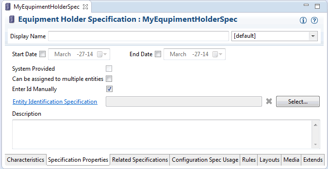
The id attribute differs from the entityId attribute: Only entities that are defined with the id attribute can be defined with the Entity Identification pattern. All entities define the entityId attribute, which is always unique across the entire database.For entities that define the Entity Identification pattern, the specification editor includes the Enter Id Manually check box, as shown in Figure 2-8. When the check box is selected, it indicates that when creating an instance of the specification in UIM, you must manually enter the id attribute value through the UIM UI.
In Figure 2-8, the Enter Id Manually check box is selected, and the option to select an Entity Identification Specification is disabled.
Figure 2-8 Specification Editor: Enter Id Manually Selected
Description of ''Figure 2-8 Specification Editor: Enter Id Manually Selected''
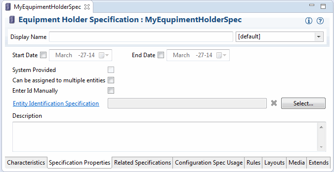
When the Enter Id Manually check box is deselected, it indicates that when creating an instance of the specification in UIM, the id attribute value is automatically generated. In Figure 2-9, the Enter Id Manually check box is deselected, and the option to select an Entity Identification Specification is now enabled.
Figure 2-9 Specification Editor: Enter Id Manually Deselected
Description of ''Figure 2-9 Specification Editor: Enter Id Manually Deselected''
When the id attribute value is to be automatically generated (Enter Id Manually is deselected, which is the default), UIM uses the SequenceGenerator interface to obtain a sequence that is used to set the id attribute value. You can optionally format the id attribute value by selecting an Entity Identification specification. When you click Select, a list of all previously defined Entity Identification specifications displays. If no Entity Identification specification is selected, a context-based sequence is generated and used to set the id attribute value. For example, in this scenario the context is the Equipment Holder entity type, resulting in the sequence being unique across all equipment holders.
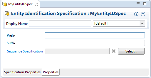
Figure 2-10 shows the Entity Identification Specification Properties tab, where you can define the sequence format. For instructions on how to create an Entity Identification Specification, see the Design Studio Help.
Figure 2-10 Entity Identification Specification Editor
Description of ''Figure 2-10 Entity Identification Specification Editor''
Based on the Entity Identification specification, the id attribute value is generated as:
prefix + sequence + suffix
where:
-
prefix is the Prefix value specified by the Entity Identification specification. Specifying a prefix is optional.
-
sequence is a unique sequence value based on Sequence specification criteria. Specifying a Sequence Specification is required.
-
suffix is the Suffix value specified by the Entity Identification specification. Specifying a suffix is optional.
Note:
You can choose to not specify the prefix or suffix. For example, to have your id attribute value incremented by 100, define an Entity Identification specification with no prefix or suffix, and specify a Sequence specification that defines an increment value of 100.Additional Tools
Third-party tools such as Ant, Drools, and Groovy are used to extend UIM:
-
Ant is used to extend the UIM data model, web services, and user interface.
Ant is an open source software tool for automating a build process. Ant uses XML to describe a build process and its dependencies. When extending the UIM data model, web services, or user interface, Ant targets are run from within Design Studio. See "Installing, Configuring, and Using Ant" for more information.
-
Drools is used to extend UIM through rulesets.
Drools is an open source project that enables accessing, changing, and managing business rules. When extending UIM using rulesets with Drools, Oracle recommends that you install the Drools Eclipse plug-ins in Design Studio. The plug-ins provide a Drools editor, and Drools-specific menu options. See "Installing, Configuring, and Using the Drools Eclipse Plug-ins" for more information.
-
Groovy is also used to extend UIM through rulesets.
Groovy is an open source project that enables accessing, changing, and managing business policies. When extending UIM using rulesets with Groovy, Oracle recommends that you install the Groovy Eclipse plug-ins in Design Studio. The plug-ins provide a Groovy editor. See "Installing, Configuring, and Using the Groovy Eclipse Plug-ins" for more information.
Installing, Configuring, and Using Ant
This section provides information on:
Downloading Ant
To download Ant:
-
Go to the following website:
-
Scroll down and click the apache-ant-releaseNumber-bin.zip link, where releaseNumber is the latest patch of the recommended Ant software release version. See "Software Requirements" for information on the Ant version.
The File Download window appears.
-
Click Save.
The Save As window appears.
-
Navigate to a local directory such as tempDir and click Save.
Installing Ant
To install Ant:
-
In your local hard drive root directory, or in your Program Files directory, create a new directory named ant.
-
Open the tempDir/apache-ant-releaseNumber-bin.zip file where releaseNumber is the latest patch recommended Ant software release version. See "Software Requirements" for information on the Ant version.
-
Extract the file contents to the ant directory you created in step 1.
Configuring Ant
To configure Ant:
-
From the Windows Start menu, select Control Panel, then select System.
The System Properties window appears.
-
Click the Advanced tab.
-
Click Environment Variables.
The Environment Variables window appears.
-
Define a new system variable named ANT_HOME:
-
In the System Variables section, click New.
The New System Variables window appears.
-
In the Variable name field, enter ANT_HOME.
-
In the Variable value field, enter the path to the extracted directory. For example, C:/ant/apache-ant or C:/Program Files/ant/apache-ant.
-
Click OK.
-
-
Update the existing system variable Path:
-
In the System Variables section, select Path, then click Edit.
The Edit System Variables window appears.
-
In the Variable value field, add the path to the bin directory of the extracted Ant directory.
For example, C:/ant/apache-ant/bin or C:/Program Files/ant/ apache-ant/bin.
-
Click OK.
The Environment Variables window appears.
-
-
Click OK.
The System Properties window appears.
-
Click OK.
Running Ant Targets
This procedure is applicable only if the cartridge you imported contains a build.xml file that defines Ant targets.
To run an Ant target within Design Studio:
-
Open the Java perspective.
For instructions on how to open the Java perspective, see the Design Studio Help.
-
From the Window menu, select Show View, then select Ant.
The Ant window appears.
-
Within the Ant window, right-click and select Add Buildfiles.
The Buildfile Selection window appears.
-
Navigate to and select the file that contains the Ant target you plan to run.
-
Click OK.
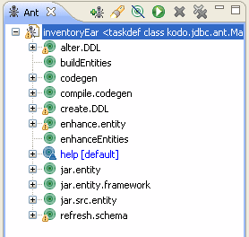
The Ant targets defined in the selected file appear in the Ant window, as shown in Figure 2-11.
-
Double-click a target.
The Ant target runs.