9 Services
This chapter describes how you model services in Oracle Communications Unified Inventory Management (UIM).
About Services
A service represents the way that a product is realized and delivered to a customer. For example, if you sell DSL Gold as a product, it is delivered as a DSL Gold service, enabled by appropriate resources.
You define Service specifications to record basic information about the service. You define Service Configuration specifications to record versionable sets of facts about the service. As these facts evolve over time, you can create new configuration versions. See "Configurations" for more information.
When you define a Service specification, you determine if the service can be assigned to multiple entities and if it can assign entities that allow multiple assignments. See "Consumption" for more information about consumption and shared consumption.
Creating a Service and a Service Configuration in UIM
To create a service and service configuration in UIM, do the following:
-
Create a service using the Service specification
-
Add a service configuration to the service by selecting a Service Configuration specification
-
Add configuration items to the service configuration
-
Modify or enter any characteristics
-
Manually assign or reference resources to configuration items or use the auto configure feature. To use the auto configure feature, you must extend the product. See UIM Developer's Guide for information about extending UIM.
-
Validate the service configuration and the service. The default validation checks date integrity, but you can extend the product to include customized validations. See UIM Developer's Guide for information about extending UIM.
-
Approve, issue, and complete the service configuration using the Actions menu.
See the UIM Help for the detailed steps to create services, to create service configurations, and to assign resources.
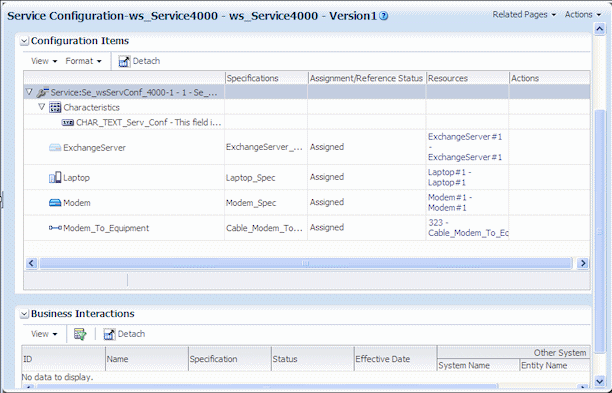
Figure 9-1 shows a Service configuration with several configuration items in UIM.
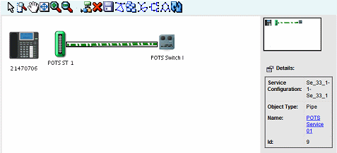
Service Topology
The service topology shows the service resources on a graphical canvas similar to the network topology canvas. You access the service topology from the Related Pages menu.
See "Networks" for more information about the canvas and the UIM Help for more detailed information about using the canvas tools.
You can move entities on the canvas and save views. You can also select an entity and view its summary information. You can also modify the graphics shown for an entity type by adding a graphic file to the entity specification through the Media tab in Design Studio.
The service topology displays assigned items that can include equipment, pipes, logical devices, network nodes and edges, places, and physical devices. UIM can be extended to include trails and termination points. See UIM Developer's Guide for more information about extending UIM.
The service topology in Figure 9-2 shows customer premise equipment, a subscriber terminal, a switch, and the pipe connecting the terminal and switch.
About Network-Oriented Services
UIM supports network-oriented services that include multipoint and point-to-point packet connectivity. For example, the Carrier Ethernet sample cartridge includes specifications for E-Line, E-LAN, and E-Tree services. Each of these Service specifications is accompanied by a matching Service Configuration specification.
Note:
Network service configurations have a different life cycle from those of other service configurations. They do not have to be complete before the creation of a new configuration.Similarly, the Packet and DSL sample cartridges contain specifications for services related to other packet technologies.
A multipoint or rooted multipoint service comprises the following elements, which are included as configuration items in the service configuration:
-
A service network. The service network provides a unified view of the service. It includes the devices and connectivities that fulfill the service. See "About Service Networks" for more information.
-
Member services. A separate member service is created for each service location. Each member service includes the service location, network access connectivity, and packet virtual network (PVN). A member service cannot be created without a parent network service.
In Design Studio, specifications for member services are defined as configuration items in the configuration specification associated with the network service specification.
Point-to-point services do not require separate network and member service entities. A single Service entity, such as one created from the E-Line Service specification provided in the Carrier Ethernet sample cartridge, represents the service as a whole. The point-to-point service configuration includes items for:
-
Two service locations.
-
One or two UNI connectivities. At least one UNI is required. If the second UNI is not specified, the corresponding service location is considered outside the provider network.
-
One to many PVNs. At least one PVN is required. A separate PVN can be used for each service location, however.
-
A single Service connectivity representing the end-to-end connectivity.
Only the Service connectivity is assigned to the service; the remaining items are referenced.
High-Level Steps for Creating a Network-Oriented Service
You follow a general order of operations when creating and configuring a network-oriented service. There might be minor variations depending on the particular technology and service type you are creating.
Depending on your business practices, all or some of these operations can be completed by web services rather than manual activities in the UIM user interface.
-
Create service locations and network locations.
Service locations represent customer sites where service is delivered. Network locations represent sites where you have installed network equipment. See "Property Locations" for more information.
-
Create logical devices in the relevant locations.
You use Logical Device entities to model routers, multiplexers, DSLAMs, and other network devices. Sample specifications for packet devices are provided in the Carrier Ethernet and DSL sample cartridges. You can also design your own specifications in Design Studio for specific devices used in your network.
See "Associating Logical Devices with Network Locations and Network Entity Locations" for more information about locating devices.
-
Create and design connectivity between logical devices.
The type of connectivity you use depends on the technology and network type. For example, a Carrier Ethernet network can include UNI, INNI, and ENNI connectivities. ATM and Frame Relay technologies have their own connectivities.
See Chapter 15, "Packet Connectivity" for more information about packet connectivity. See UIM Carrier Ethernet Cartridge Guide for detailed information about using the sample Connectivity specifications provided in that cartridge.
-
Create the PVNs needed for the service. In multipoint services, there may be multiple PVNs. For point-to-point services, there is usually only one.
Different technologies have different PVNs. The Carrier Ethernet sample cartridge includes specifications for EVCs, OVCs, and other networks. See "About Packet Virtual Networks" for more information.
-
Add flow identifiers to PVNs.
Flow identifiers represent the tags used by different technologies to distinguish packets as they flow through interfaces in the network. Each network technology has its own set of flow identifiers, such SP-VLAN IDs and CE-VLAN IDs for Carrier Ethernet or DLCIs for Frame Relay. See "About Flow Identifiers" for more information.
-
Set class of service, quality of service, and bandwidth profile attributes for the PVN as a whole and for individual flow interfaces.
In UIM, these attributes are modeled as Custom Object entities with characteristics that represent the various metrics. Examples of bandwidth profile, class of service and other performance parameter specifications are included in the Packet and Carrier Ethernet cartridges. See "Performance Parameters" for more information.
-
For multipoint services (such as Ethernet E-LAN or E-Tree):
-
Configure a member service for each service location.
-
Reference a PVN and an access connectivity for each member service.
-
Create a Service connectivity for each member service.
-
Create the network service and service configuration.
-
Assign the member services to the network service configuration.
-
-
For point-to-point services (such as Ethernet E-Line):
-
Create the service and service configuration.
-
Reference the PVN and access connectivities.
-
Create a Service connectivity.
-
-
Issue, approve, and complete all services.
Automated Validations and Configurations During Network Service Creation
UIM partially automates the validation and configuration of network-oriented services. Validation ensures that the Service configuration includes the information required to automatically create a Service connectivity and a Service network. The Service network provides an end-to-end view of the service.
In addition to the actions listed in the following sections, UIM performs validations and automatic life cycle transitions related to deleting, canceling, and disconnecting services. These validations ensure that all related services and configurations are in compatible statuses after an action. For example, if you cancel a network service, UIM validates that all member services are in Disconnected or Canceled status before setting the network service status to Canceled.
Member Service Automated Validations and Configuration
When you assign a Service connectivity to a member service, UIM:
-
Validates that the A service location is provided.
-
Validates that the access connectivity is provided.
-
Validates that the access connectivity is terminated on a device interface.
-
Validates that the PVN is provided.
-
Validates that the member service is part of a network service.
-
Validates that a service network exists on the network service.
-
Validates that a Trunk flow interface exists in the PVN on the same logical device as the access connectivity device interface termination or that an Internetwork interface exists in the PVN.
If the validations are successful, UIM automatically:
-
Creates and designs the service connectivity.
-
Sets the A Location to the service location.
-
Sets the Z location to the Z termination of the access connectivity.
-
Sets the CIR and MIR (if a bandwidth profile exists in the Service configuration).
-
Sets the connectivity function to match the service network function.
-
Automatically designs the service connectivity to ride the access connectivity.
-
Assigns any flow identifiers assigned in the Service configuration to the service connectivity.
-
Automatically associates the service connectivity to the service network in Pending Install status.
When you complete a member service, UIM automatically:
-
Sets the member service configuration status to Completed.
-
Sets the member service status to In Service.
-
Sets the service connectivity configuration status to Completed.
-
Sets the service connectivity status to Installed.
-
Validates the PVN to ensure that:
-
All service connectivities are in Assigned or Pending Assigned status.
-
All service connectivities are cross-connected to the PVN.
-
All connectivities referenced in the service network are in Completed status.
-
The service connectivity can now be viewed in the Current context and is listed as Installed in the service network.
Network Service Automated Validation and Configuration
When you create a new network service, UIM automatically:
-
Creates a service configuration.
This behavior requires that the uim.entity.autoCreateDefaultVersion system configuration parameter be set to true. See UIM System Administrator's Guide for more information.
-
Builds the service network.
-
Assigns the service network to the network service.
-
Creates a service network configuration.
When you complete a network service, UIM:
-
Validates that all member services are in Completed status.
Note that UIM does not automatically complete member services. You must complete each member service individually.
-
Changes the service network configuration from In Progress status to Completed.
-
Validates the service network. This validation is the same as a manual validation of the network.
-
Validates that all member services have a service location.
-
Validates that all service locations for the member services are in the service network.
-
Validates that all connectivity referenced in the service network is in Completed status.
About Products
Product entities are included in UIM for backward compatibility with customized solutions that require mapping services to corresponding products.The UIM navigation section does not include a Product link unless the user is authorized to access the Product Search page. Access is turned off by default. See UIM System Administrator's Guide for information about authorizing user access.
You can clone or modify existing Product specifications in Design Studio. See Design Studio Help for more information.