Introduction to Network Load Balancer
Learn about how network load balancers can provide automated traffic distribution from one entry point to multiple servers in a backend set.
Modes of Operation
Network Load Balancer is a load balancing service which operates at Layer-3 and Layer-4 of the Open Systems Interconnection (OSI) model. This service provides the benefits of high availability and offers high throughput while maintaining ultra low latency. You have three modes in Network Load Balancer in which you can operate:
-
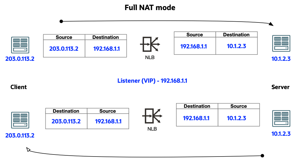
Full Network Address Translation (NAT) mode: Network Load Balancer translates both source IP address and destination IP address of the packet before sending it across to the backend.
-
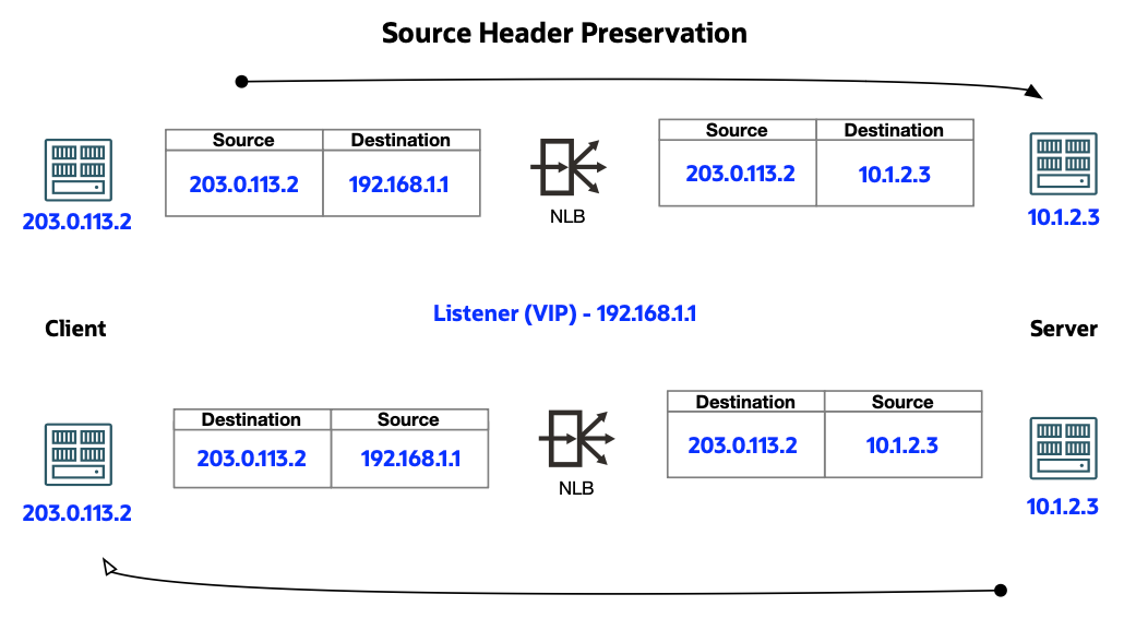
Source Preservation mode: Network Load Balancer does a destination NAT from the Network Load Balancer listener (VIP) to the backend server IP address. However, it preserves the original source IP address/port information before sending it to the backend server.
-
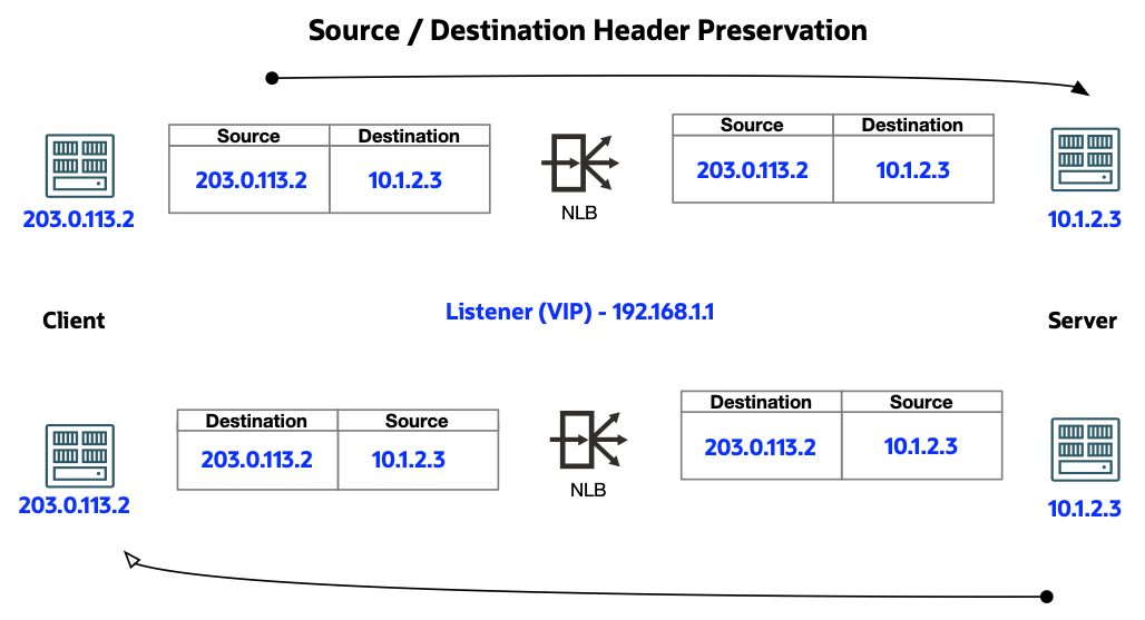
Transparent (Source/Destination Preservation) mode: Network Load Balancer doesn't change any information in the packet. This mode forwards the packets to the backend servers, effectively operating as a "bump-in-the-wire." This mode requires the traffic be directed through it by using a VCN routing table entry.
The following table answers questions regarding the Network Load Balancer modes of operation.
| Mode | Other Names | Where Enabled? | Does Client Traffic Use the Listener? | Public Network Load Balancers Support? | Private Network Load Balancers Support? |
|---|---|---|---|---|---|
| Full NAT | None | Enabled by disabling both Source Header Preservation and Source/Destination Header Preservation modes. | Yes | Yes | Yes |
| Source Header (IP/Port) Preservation |
|
Enabled through the Backend Set configuration (create or edit). | Yes | Yes | Yes |
| Source/Destination Header (IP/Port) Preservation |
|
Enabled in the Network Load Balancer Details page. | No | No | Yes |
Network Load Balancer Types
The Flexible Network Load Balancer service enables you to create a public or private network load balancer in your VCN. A public network load balancer has a public IP address that is accessible from the internet. A private network load balancer has an IP address from the hosting subnet, which is visible only within your VCN. You can configure several listeners for an IP address to load balance Layer 4 (TCP/UDP/ICMP) traffic. Both public and private load balancers can route data traffic to any backend server that's inside the VCN.
Public Network Load Balancer
To accept traffic from the internet, create a public network load balancer. The service assigns it a public IP address that serves as the entry point for incoming traffic. Associate the public IP address with a friendly DNS name through any DNS vendor.
A public network load balancer can be either regional or availability domain-specific in scope. The subnet in which the network load balancer is created determines this scope. A public network load balancer created in a regional subnet is regional in scope. A public network load balancer created in an availability domain-specific subnet is availability domain-specific in scope. Network Load Balancer ensures high availability and accessibility even when one of the availability domains has an outage.
You can't specify a private subnet for your public load balancer. For more information, see Public vs. Private Subnets.
Private Network Load Balancer
To isolate the network load balancer from the internet and simplify your security posture, create a private network load balancer. The network load balancer assigns it a private IP address that serves as the entry point for incoming traffic. The network load balancer is accessible only from within the VCN that contains the host regional subnet, or as further restricted by your security rules.
A private network load balancer can be either regional or availability domain-specific in scope. The subnet in which the network load balancer is created determines this scope.
Network Load Balancer Reachability
The network load balancer doesn't directly respond to a client ICMP or TCP/UDP ping packet. Instead, the network load balancer directs the packet to a backend server in accordance with the load balancing policy. The backend server then returns a response to the client.
Only private network load balancers support the ICMP protocol. The network load balancer must also have the Source/Destination Header (IP, Port) Preservation feature enabled. If this feature isn't enabled, or if you're using a public network load balancer, you can check the network load balancer's reachability through available listener-enabled protocols (TCP/UDP).
Using a Private Network Load Balancer as Next Hop Route Target with VCN Transit Routing
Use a private network load balancer as the next-hop private IP route target with VCN transit routing. This method enables the network load balancer to operate as a bump-in-the-wire layer 3 transparent load balancer to which packets are forwarded along the path to their final destination. Transit routing refers to a network topology in which your on-premises network uses a connected virtual cloud network (VCN) to reach Oracle resources or services beyond that VCN. Connect the on-premises network to the VCN with FastConnect or Site-to-Site VPN, and then configure the VCN routing so that traffic transits through the VCN to its destination beyond the VCN. See Transit Routing inside a hub VCN for more information.
The network load balancer routes user traffic to the firewall instances hosted behind network load balancer in the Hub VCN using VCN route tables. This user traffic that would otherwise flow from source directly to destination. In this mode, network load balancer does not modify the client packet characteristics and preserves the client source and destination IP header information. This method enables the firewall appliances to inspect the original client packet and apply security policies before forwarding it to the application backend servers in the spoke VCNs.
The following illustrates the network load balancer architecture.

|
Destination |
Target |
|---|---|
|
10.0.0.0/24 |
Flex-NLB VIP IP |
|
10.1.0.0/24 |
Flex-NLB VIP IP |
|
Destination |
Target |
|---|---|
|
172.16.0.0/16 |
DRG |
|
Destination |
Target |
|---|---|
|
0.0.0.0/0 |
IGW |
|
Destination |
Target |
|---|---|
|
10.0.0.0/24 |
Hub Web LPG |
|
10.1.0.0/24 |
Hub DB LPG |
|
Destination |
Target |
|---|---|
|
0.0.0.0/0 |
FW Trust Int IP |
All Network Load Balancers
Your network load balancer has a backend set to route incoming traffic to your compute instances. The backend set is a logical entity that includes:
- A list of backend servers
- A load balancing policy
- A health check policy
The backend servers (compute instances) associated with a backend set can exist anywhere, as long as the associated network security groups (NSGs), security lists, and route tables allow the intended traffic flow.
If your VCN uses network security groups (NSGs), you can associate your load balancer with an NSG. An NSG has a set of security rules that controls allowed types of inbound and outbound traffic. The rules apply only to the resources in the group. Contrast NSGs with a security list, where the rules apply to all the resources in any subnet that uses the list. See Network Security Groups for more information about NSGs.
If you prefer to use security lists for your VCN, the Load Balancing service can suggest appropriate security list rules. You also can configure them yourself through the Networking service. See Security Lists for more information. For detailed information comparing NSGs and security lists, see Security Rules.
We recommend that you distribute your backend servers across all availability domains within the region.
Private IP Address Consumption
A public network load balancer created in a public subnet consumes one private IP address from the host subnet.
A private network load balancer created in a single subnet consumes one private IP address from the host subnet.
Network Load Balancer Concepts
- BACKEND SERVER
- An application server responsible for generating content in reply to the incoming client traffic. You typically identify application servers with a unique combination of overlay (private) IPv4 address and port, for example, 10.10.10.1:8080 and 10.10.10.2:8080. For more information, see Backend Servers for Network Load Balancers.Note
The backend server cannot function as both a client and a backend simultaneously as it's unable to start traffic to the network load balancer's virtual IP (VIP). - BACKEND SET
- A logical entity defined by a list of backend servers, a load balancing policy, and a health check policy. The backend set decides how the network load balancer directs traffic to the collection of backend servers. For more information, see Backend Sets for Network Load Balancers.
- HEALTH CHECK
-
A health check is a test to confirm the availability of backend servers. A health check can be a request or a connection attempt. Based on a time interval you specify, the load balancer applies the health check policy to continuously monitor backend servers. If a server fails the health check, the load balancer takes the server temporarily out of rotation. If the server later passes the health check, the load balancer returns it to the rotation.
You configure your health check policy when you create a backend set. You can configure TCP-level, UDP-level, or HTTP-level health checks for your backend servers.
- TCP-level health checks attempt to make a TCP connection with the backend servers and validate the response based on the connection status.
- UDP-level health checks attempt to make a UDP connection with the backend servers and validate the response based on the connection status.
- HTTP-level health checks send requests to the backend servers at a specific URI and validate the response based on the status code or entity data (body) returned.
The service provides application-specific health check capabilities to help you increase availability and reduce your application maintenance window. For more information on health check configuration, see Health Check Policies for Network Load Balancers.
- HEALTH STATUS
- An indicator that reports the general health of your network load balancers and their components. For more information, see Health Status for Network Load Balancers.
- LISTENER
- A logical entity that checks for incoming traffic on the network load balancer's IP address. You configure a listener's protocol and port number. Supported protocols include:
- UDP
- TCP
- UDP/TCP
- TCP/UDP/ICMP (private only)
- L3 IP
Note
Private network load balancers only support the ICMP protocol if the Source/Destination Header (IP, Port) Preservation feature is enabled. See Enabling Network Load Balancer Backend Set Source Preservation for more information. For more information, see Listeners for Network Load Balancers.
- NETWORK LOAD BALANCING POLICY
- A network load balancing policy tells the network load balancer how to distribute incoming traffic to the backend servers. Common load balancer policies include:
- 5-Tuple Hash
- 3-Tuple Hash
- 2-Tuple Hash
- REGIONS AND AVAILABILITY DOMAINS
- The Network Load Balancer service manages application traffic across availability domains within a region . A region is a localized geographic area, and an availability domain is one or more data centers located within a region. A region is composed of several availability domains. For more information, see Regions and Availability Domains.
- SUBNET
- A subdivision you define in a virtual cloud network (VCN), such as 10.0.0.0/24 and 10.0.1.0/24. A subnet consists of a contiguous range of IP addresses that do not overlap with other subnets in the VCN. For each subnet, you specify the routing and security rules that apply to it. For more information on subnets, see VCN and Subnet Management and Public IP Address Ranges.
- TAGS
-
You can apply tags to your resources to help you organize them according to your business needs. You can apply tags at the time you create a resource, or you can update the resource later with the wanted tags. For general information about applying tags, see Resource Tags.
- VIRTUAL CLOUD NETWORK (VCN)
- A private network that you set up in the Oracle data centers, with firewall rules and specific types of communication gateways that you can choose to use. A VCN covers a single, contiguous IPv4 CIDR block of your choice in the allowed IP address ranges. You need at least one virtual cloud network before you launch a network load balancer. For information about setting up virtual cloud networks, see Networking Overview.
- VISIBILITY
- Specifies whether your network load balancer is public or private.
- WORK REQUEST
- An object that reports on the current state of a network load balancer request. Network Load Balancer handles requests asynchronously. Each request returns a work request ID (OCID) as the response. You can view the work request item to see the status of the request. For more information, see Work Requests for Network Load Balancers.
Resource Identifiers
Most types of Oracle Cloud Infrastructure resources have a unique, Oracle-assigned identifier called an Oracle Cloud ID (OCID). For information about the OCID format and other ways to identify your resources, see Resource Identifiers.
Ways to Access Oracle Cloud Infrastructure
You can access Oracle Cloud Infrastructure (OCI) by using the Console (a browser-based interface), REST API, or OCI CLI. Instructions for using the Console, API, and CLI are included in topics throughout this documentation. For a list of available SDKs, see Software Development Kits and Command Line Interface.
Monitoring Resources
You can monitor the health, capacity, and performance of Oracle Cloud Infrastructure resources by using metrics, alarms, and notifications. For more information, see Monitoring and Notifications.
For information about monitoring the traffic passing through your network load balancer, see Network Load Balancer Metrics.
Authentication and Authorization
Each service in Oracle Cloud Infrastructure integrates with IAM for authentication and authorization, for all interfaces (the Console, SDK or CLI, and REST API).
An administrator in an organization needs to set up groups , compartments , and policies that control which users can access which services, which resources, and the type of access. For example, the policies control who can create new users, create and manage the cloud network, create instances, create buckets, download objects, and so on. For more information, see Managing Identity Domains. For specific details about writing policies for each of the different services, see Policy Reference.
If you're a regular user (not an administrator) who needs to use the Oracle Cloud Infrastructure resources that the company owns, contact an administrator to set up a user ID for you. The administrator can confirm which compartment or compartments you can use.
Limits on Network Load Balancers
Each load balancer has the following configuration limits:
- One IPv4 address and one IPv6 address
- 50 backend sets
- 512 backend servers per backend set
- 1024 backend servers total
- 50 listeners
- Default limit of 330,000 concurrent connections per availability domain
For a list of applicable limits and instructions for requesting a limit increase, see Limits by Service
Required IAM Policies
To use Oracle Cloud Infrastructure, an administrator must be a member of a group granted security access in a policy by a tenancy administrator. This access is required whether you're using the Console or the REST API with an SDK, CLI, or other tool. If you get a message that you don't have permission or are unauthorized, verify with the tenancy administrator what type of access you have and which compartment your access works in.
For administrators: For a typical policy that gives access to load balancers and their components, see Let network admins manage load balancers.
Also, be aware that a policy statement with inspect load-balancers gives the specified group the ability to see all information about the load balancers. For more information, see Details for Load Balancing.
If you are new to policies, see Getting Started with Policies and Policy Builder Policy Templates.
Network Load Balancer Policies
After you create a network load balancer, you can apply policies to control traffic distribution to your backend servers. See Creating a Network Load Balancer.
The Network Load Balancer service supports three primary network load balancer policy types:
-
5-Tuple Hash: Routes incoming traffic based on 5-Tuple (source IP and port, destination IP and port, protocol) Hash. This is the default network load balancer policy.Note
When the L3 IP listener protocol is selected, the load balancer doesn't support 5-Tuple hash policies. - 3-Tuple Hash: Routes incoming traffic based on 3-Tuple (source IP, destination IP, protocol) Hash.
- 2-Tuple Hash: Routes incoming traffic based on 2-Tuple (source IP, destination IP) Hash.
The 5-Tuple Hash policy provides session affinity within a given TCP or UDP session, where packets in the same session are directed to the same backend server behind the flexible network load balancer. Use a 3-Tuple or 2-Tuple network load balancing policy to provide session affinity beyond the lifetime of a given session.
When processing load or capacity varies among backend servers, you can refine each of these policy types with backend server weighting. Weighting affects the proportion of requests directed to each server. For example, a server weighted as 3 receives three times the number of connections as a server weighted as 1. You assign weights based on criteria of your choosing, such as each server's traffic-handling capacity. Weight values must be from 1 to 100.
Connections Idle Timeout
The network load balancer tracks the state of all TCP and UDP flows passing through it. A combination of IP protocol and source and destination IP addresses and ports define a flow. The flow can be removed if no traffic is received from either the client or the server for longer than the idle timeout. Any TCP packets received after the idle timeout are dropped. For UDP flows, a later packet is considered as a new flow and routed to a new backend server.
The idle timeout duration for TCP flows is 6 minutes and for UDP flows is 2 minutes. You can adjust these times when creating a listener for a network load balancer, and also when editing an existing listener. See Changing a Listener's Idle Timeout for more information.
Logging
Network load balancing activities are logged through the virtual cloud network (VCN) flow logs. See VCN Flow Logs for more information.
Encryption
The Network Load Balancer service doesn't directly change any traffic that it receives. Therefore, to secure the traffic being sent through the network load balancer to the backends, you're responsible for encrypting the applications on the backends receiving the traffic. To incorporate SSL termination on a load balancer, use the Load Balancer service instead.