Completing the Initial Setup and Configuration from the Graphical User Interface
Using the GUI during first boot is the preferred way to perform the Compute Cloud@Customer Isolated initial setup and configuration.
Only administrators with proper certification from Oracle are allowed to perform these operations. Limited access to administration functions (Service Enclave) is provided to members of the C3IsolatedGroup authorization group.
This entire procedure is best performed as one workflow. It's broken down into sections to improve navigation and clarity.
Preparing the OCI Home Tenancy
An edge cloud system with a link to OCI cannot be initialized until its home OCI tenancy has been configured to accept the linked infrastructure. Before performing the initial setup and configuration procedure, ensure that these prerequisites are met:
-
Customer account with access to an OCI tenancy.
-
Infrastructure resource configured in the OCI tenancy.
Note the IDs of the OCI home tenancy and the infrastructure resource. Both are required parameters to set the system operating mode.
Setting the System Operating Mode
Connect to the Compute Cloud@Customer Isolated for the first time to create a primary administration account, unlock the system, and set the parameters that determine the operating mode. Compute Cloud@Customer Isolated is linked to OCI and operates in disconnected mode with local IAM.
-
Log in to the workstation you connected to the infrastructure, and browse to
https://100.96.2.32:30099. -
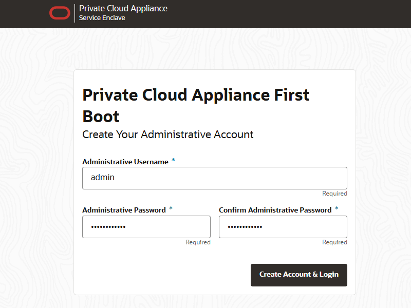
From the First Boot page, create the primary administrative account for your infrastructure, which is used for initial configuration and will persist after the first boot process. Additional accounts can be added later.
-
Enter an Administrative Username.
-
Enter and confirm the Administrative Password.
Note
Passwords must contain a minimum of 12 characters with at least one of each: uppercase character, lowercase character, digit, and any punctuation character – except for double quote ('"') characters, which are not allowed.
-
Click Create Account & Login.
Caution
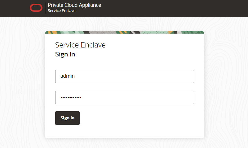
At the Service Enclave Sign In page, Do not sign in and do not refresh your browser.
-
-
Unlock the system. This step must be performed from the Service CLI.
-
Open a terminal window and log in to one of the management nodes using the primary administrative account.
Note
Management nodes are named
pcamn01,pcamn02andpcamn03by default.$ ssh admin@pcamn01 -p 30006 Password authentication Password: PCA-ADMIN> -
Enter the
systemStateunlockcommand.PCA-ADMIN> systemStateunlock -
Verify the system is unlocked.
PCA-ADMIN> show pcaSystem Data: Id = 5709f72b-c439-4c3a-8959-758df94eff25 Type = PcaSystem System Config State = Config System Params system state locked = false -
Enter the
exitcommand or close the terminal window.
-
-
Return to the browser window displaying the Service Enclave Sign In page. Use the primary administrative account to sign in.
Note
You might need to accept the self-signed SSL certificate again before signing in.
-
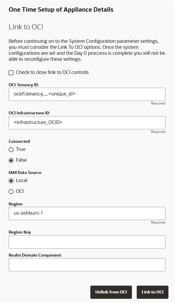
In the One Time Setup page, configure the operating mode and related system parameters.
-
Compute Cloud@Customer Isolated must be linked to OCI.
Clear the checkbox under Link to OCI. The controls to link the system to OCI are displayed.
-
Provide the following infrastructure details.
Required entries are marked with an asterisk. Pay special attention to the highlighted parameters: connection mode and IAM data source.
-
OCI Tenancy ID*
-
OCI Infrastructure ID*
-
Connected Mode*: select False
-
IAM Data Source*: select Local
-
Region*
-
Region Key
-
Realm Domain Component
-
-
Click Link to OCI to confirm the settings.
At this point you can unlink and relink to update the link settings. When you click Save Changes in the next step, all one time setup parameters are locked in and can no longer be changed.
-
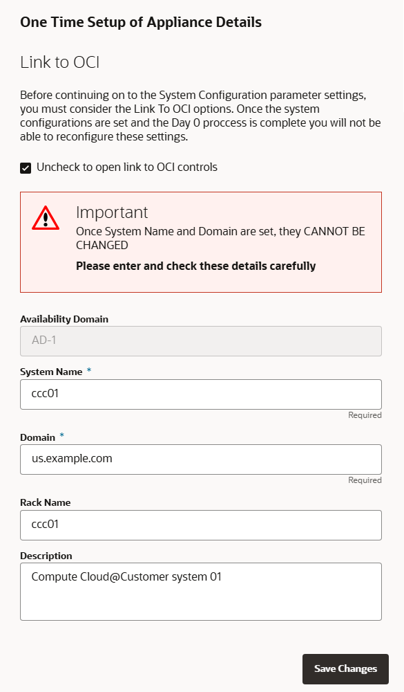
Select the checkbox under Link to OCI to hide the OCI link controls, and display the system parameters.
-
Provide the following infrastructure details.
The Availability Domain cannot be modified. Required entries are marked with an asterisk.
-
System Name*
-
Domain*
-
Rack Name
-
Description
Note
The system name and domain fields support only lowercase characters. If you enter uppercase characters in these fields, they are converted to lowercase when changes are saved.
-
-
-
Confirm the parameters you entered are correct. After this step they can no longer be changed. Click Save Changes when you are ready to proceed.
Keep the browser window open. Proceed to the next section of this initial setup procedure.
Configuring the System Network
When the operating mode and base system parameters are locked in, you must configure the system network. The Network Configuration wizard guides you through the sets of parameters you must provide. Refer to the information you gathered in the Initial System Installation Checklist to complete the system configuration. It's helpful to enter all this information in a text file.
Enter the IP addresses for the uplinks exactly as they appear in the network configuration spreadsheet you filled out in preparation. The order of entry is important, especially when multiple IPs are added in the same field, because they map to specific spine and data center switches in the uplink topology.
-
Return to the browser window you left open at the end of the preceding section. Refresh the page and sign in to the system with the primary administrative account.
Note
You might need to accept the self-signed SSL certificate again before signing in.
-
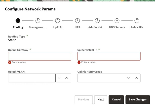
In the Configure Network Params wizard, select the routing design for the logical connection between Compute Cloud@Customer Isolated and the data center network.
The options are (A) static routing or (B) dynamic routing. The required parameters are different depending on the routing design you selected.
- Option A: Static Routing
-
Enter the following data center information:
-
Routing Type: Static*
-
Uplink gateway IP Address*
-
Spine virtual IP* (comma-separated values if using the 4 port dynamic mesh topology)
-
Uplink VLAN
-
Uplink HSRP Group
-
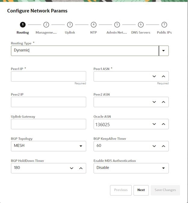
- Option B: Dynamic Routing
-
Enter the following data center information:
-
Routing Type: Dynamic*
-
Peer1 IP and ASN*
-
Peer2 IP and ASN
-
Uplink Gateway
-
Oracle ASN
Note
The default Oracle ASN is 136025. The default BGP ASN inbound path filtering does not accept your own ASN in the AS path. If there is more than one Compute Cloud@Customer Isolated site, then customers must adjust the Oracle ASN field to be unique in their data center network. -
BGP Topology (square, mesh, triangle), KeepAlive Timer and HoldDown Timer
-
MD5 Authentication: enable or disable
Note
Communication between VCNs on different DRGs within a Compute Cloud@Customer Isolated environment is possible if route entries and firewall access are provided on the data center network that connects the two VCNs.
-
-
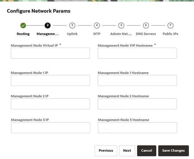
Click Next to proceed to the wizard page for management node network parameters.
Enter a shared virtual IP and associated host name for the management node cluster. Add an IP address and host name for each of the three individual management nodes.
-
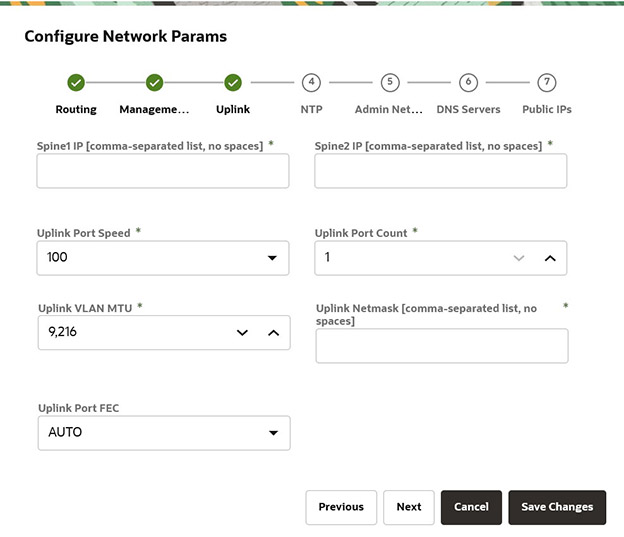
Click Next to proceed to the wizard page for uplink parameters.
Enter the following data center uplink information:
-
IP Address for Spine Switch 1 and 2*
-
Uplink Port Speed and Port Count*
-
Uplink VLAN MTU and Netmask*
-
Uplink Port FEC
Note
Uplinks ports are always configured as port channels, even when only one uplink port count is configured. Port channel is configured with LACP mode with LACP rate as fast.
-
-
Click Next to proceed to the wizard page for NTP parameters.
Enter the IP address or fully qualified domain name of at least one NTP server. Use a comma separated list to specify multiple NTP servers.
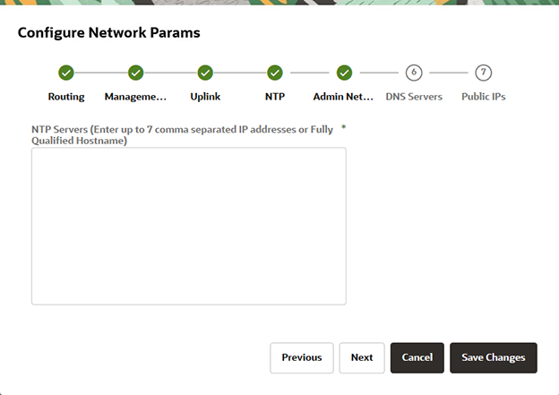
Note
When the network configuration has been applied, you can check the NTP connection status.
In the Service Web UI, it's displayed in the NTP tab of the Network Environment Information page. In the Service CLI you can run this command:
PCA-ADMIN> checkNtpServers Data: id Accessible -- ---------- 10.64.0.252 true 192.0.2.2 true -
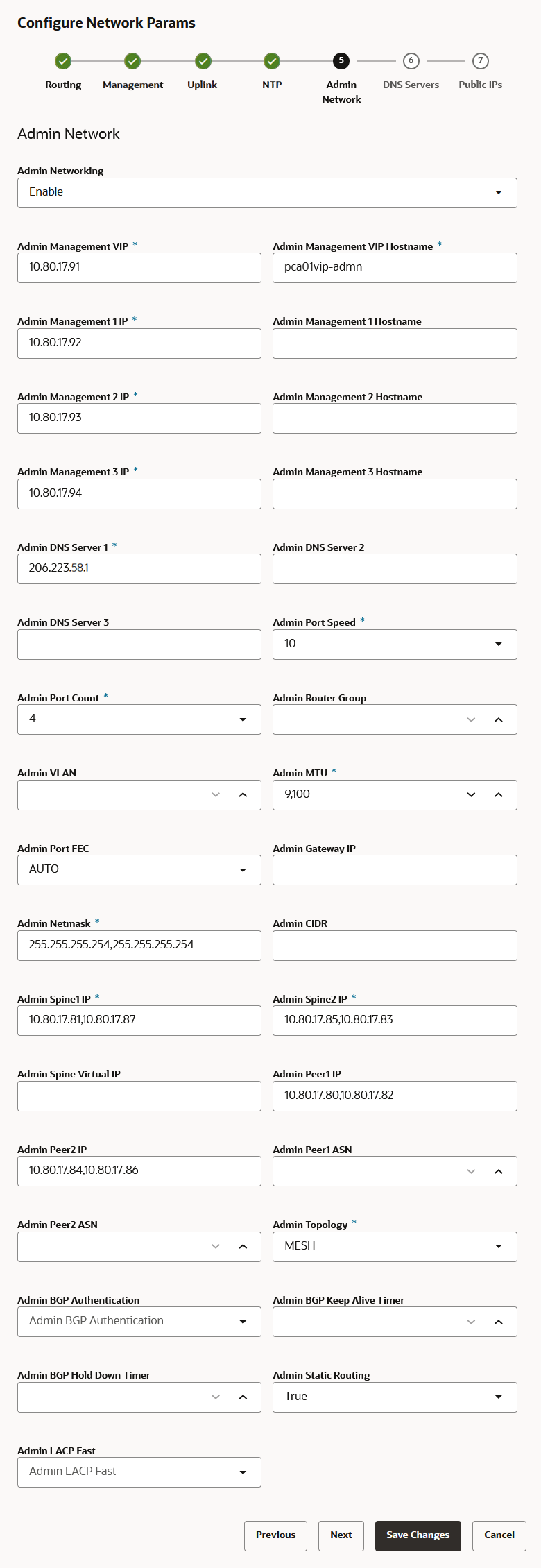
Click Next to proceed to the wizard page for Admin Network parameters.
(Optional) If you don't intend to configure a segregated infrastructure administration network, leave it disabled and skip this step.
If you elected to segregate administrative infrastructure access from the data traffic, configure the administration network by entering the following mandatory and optional information.
-
Admin Networking: Enable
-
Admin Management VIP address and Hostname
-
Admin Management 1 and 2 and 3 IP address and Hostname
-
At least 1, but up to 3, Admin DNS Server IP addresses
-
Admin Port Speed, Port Count, and Admin Router Group
-
Admin VLAN, MTU, Port FEC, and Gateway IP
-
Admin IP Address for Spine Switch 1 and 2, and a shared Virtual IP
-
Admin Peer1 and Peer2 IP address and ASN for BGP
-
Admin Topology (Triangle, Square, Mesh)
-
Admin BGP Authentication (Enable/Disable). Keepalive Timer, Hold Down Timer, and Static Routing
-
-
Click Next to proceed to the wizard page for DNS parameters.
Enter at least one and up to three DNS servers in the respective fields.
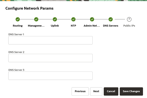
-
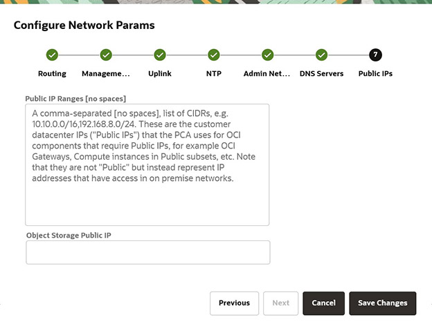
Click Next to proceed to the wizard page for public IP addresses.
Enter the data center IP addresses that the system controller software can assign to resources as public IPs.
-
Public IP list of CIDRs in a comma-separated list
-
Object Storage Public IP (must be outside the public IP range)
-
-
Keep the browser window open. Proceed to the next section of this initial setup procedure.
Verifying and Applying the Network Configuration
All parameters in all pages of the Network Configuration wizard have been entered. However, you must still verify and apply the configuration.
-
Verify the parameters you entered in each of the wizard. Use the Previous/Next buttons to scroll through the pages.
The network configuration information is persisted when a test procedure is completed successfully. Testing starts when you save the network configuration in the next step. If you need to change any parameters after testing begins, you must reenter all information.
-
Save the network configuration parameters by clicking Save Changes.
A network configuration test begins, and can take up to 15 minutes. Do not close the browser window before it's completed.
If a problem is encountered, the Configure Network Params wizard reopens and the error is displayed.
-
In the Testing Network Parameters page, select the appropriate option:
-
Click Reenter Network Configuration.
You are returned to a blank Configure Network Params wizard where you must enter all your information again.
-
Click Commit Changes.
The network parameters are locked. When locked, the routing type and public IPs cannot be changed.
Caution
When you click Commit Changes, system initialization begins and can take up to 15 minutes. Do not close the browser window during this time.
If a problem is encountered, the Configure Network Params wizard reopens and the error is displayed. Otherwise, a Configuration Complete message is displayed.
-
-
Click Sign Out. You are returned to the Service Enclave sign in page.
-
Verify the system configuration.
-
Connect to the Service Web UI at the new virtual IP address of the management node cluster:
https://<virtual_ip>:30099. -
From the Dashboard, click Appliance to view the system details and click Network Environment to view the network configuration.
Note
Alternatively, you can log in to the Service CLI as an administrator and run the following commands to confirm your entries.
# ssh 100.96.2.32 -l admin -p 30006 PCA-ADMIN> show pcaSystem PCA-ADMIN> show networkConfig -