Data Flows
A data flow is a visual program representing the flow of data from source data assets, such as a database or flat file, to target data assets, such as a data lake or data warehouse.
The following pages describe how to list, build, and manage data flows in Data Integration:
- Listing Data Flows
- Creating a Data Flow
- Using Data Flow Operators
- Using Data Flow Parameters
- Editing a Data Flow
- Refreshing Entities in a Data Flow
- Moving a Data Flow
- Duplicating a Data Flow
- Deleting a Data Flow
- Functions (Data Flow) Reference
The Data Integration intuitive UI designer opens when you create, view, or edit a data flow.
See Design Concepts for a high-level overview of basic concepts behind the interactive designer. You can also watch the Data Integration's data flow designer interactive video for a hands-on introduction to data flows.
The following pages describe how to export and import a data flow:
Design Concepts
An understanding of the following basic concepts is helpful when using the interactive designer in Data Integration.
A schema defines the shape of data in a source or target system. When working on a data flow in Data Integration, schema drift occurs when the data definitions change.
For example, an attribute might be added or removed in the source, or an attribute in the target might be renamed. If you don't handle schema drift, the ETL processes might fail or you might lose data quality.
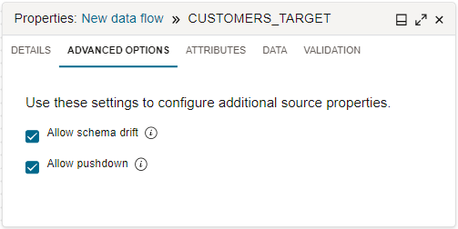
By default, Data Integration handles schema drift for you. When you configure a source operator in the data flow designer, after selecting a data entity, select the Advanced Options tab on the Properties panel. The selected Allow Schema Drift checkbox indicates that schema drift is enabled.
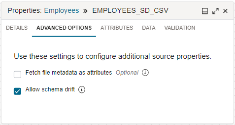
When schema drift is enabled, Data Integration can detect schema definition changes in the specified data entities during data flow design time and runtime. Any changes are automatically picked up and the schema adapted to accommodate new attributes, removed attributes, different attribute names, changed data types, and so on.
If you clear the Allow Schema Drift checkbox, you disable schema drift to lock the schema definitions when the data flow is defined. When schema drift is disabled, Data Integration uses a fixed shape of the specified data entity even when the underlying shape has changed.
Without handling schema drift, data flows can become vulnerable to upstream data source changes. With the help of schema drift, data flows become more resilient and adapt automatically to any changes. You don't need to redesign the data flows when schema definition changes occur.
For a JSON file, schema drift is disabled by default and can't be enabled if a custom schema is used to infer the entity shape. If you want schema drift to be available and enabled, edit the JSON source in the data flow or data loader task and clear the Use custom schema checkbox.
In Data Integration, a data operation in a data flow can be pushed to a source or target data system for processing.
For example, a sort or filter operation can be performed in the source system while the data is being read. In the case where one of the sources for a join operation is in the same system as the target, the data operation can be pushed to the target system.
Data Integration can use pushdown in a data flow when you use relational data systems that support pushdown. The current list includes Oracle databases, Oracle Autonomous AI Lakehouse, Oracle Autonomous AI Transaction Processing, and MySQL.
By default, Data Integration uses pushdown when applicable. When you configure a source operator in the data flow designer, after selecting a data entity, select the Advanced Options tab on the Properties panel. The selected Allow Pushdown checkbox indicates that pushdown is enabled.
When pushdown is enabled, Data Integration converts applicable data operation logic into SQL statements that are then directly run on the relational database. By pushing data processing to the database, less data is pulled and loaded.
If you clear the Allow Pushdown checkbox, you disable pushdown. When pushdown is disabled, Data Integration pulls all the data from the source system and processes the data on the Apache Spark clusters allocated to theworkspace.
By letting Data Integration use pushdown, performance is improved because:
- The processing power of the database is used
- Less data is ingested for processing.
Based on optimization, Data Integration can use partial or full pushdown in a data flow. Partial pushdown is performed when a supported relational data system is used at the source or target. Full pushdown is performed when the following conditions are present:
- Only one target exists in the data flow.
- In a data flow with a single source, both the source and target use the same connection to a supported relational data system.
- In a data flow with multiple sources, all the sources must also use the same database and connection.
- All the transformation operators and functions in the data flow can generate valid pushdown SQL code.
Data preparation ensures that Data Integration processes ingest accurate and meaningful data with fewer errors to produce quality data for more reliable insights.
Preparing data includes cleansing and validating data to reduce errors, and transforming and enriching data before loading the data into target systems. For example, the data might come from different sources with various formats and even duplicate information. Data preparation might involve removing duplicate attributes and rows, standardizing on a format for all date attributes, and masking sensitive attribute data such as credit cards and passwords.
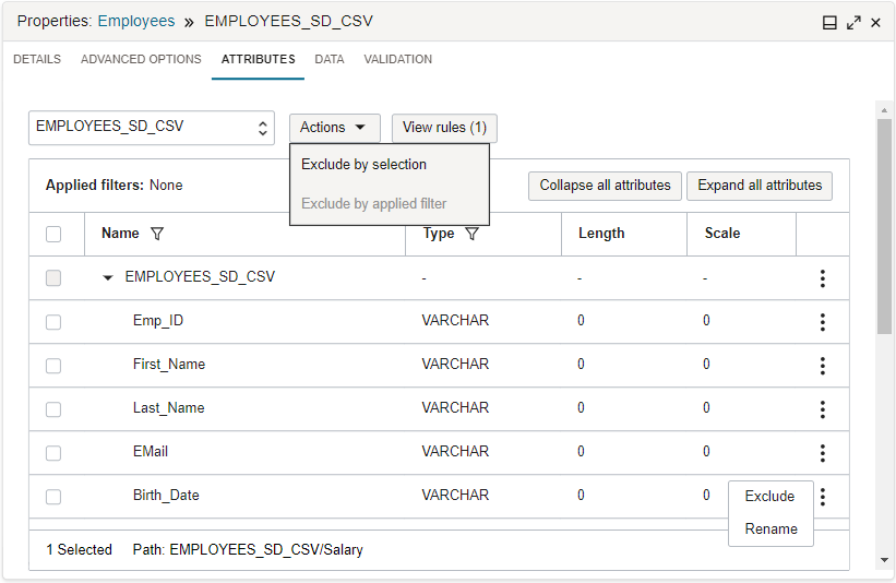
Data Integration provides out-of-the-box shaping operators and functions, and transformations that you can use in interactive tools to prepare data as you design the logic for the ETL processes. For example, the Attributes tab lets you search incoming attributes by a pattern and apply an exclude rule.
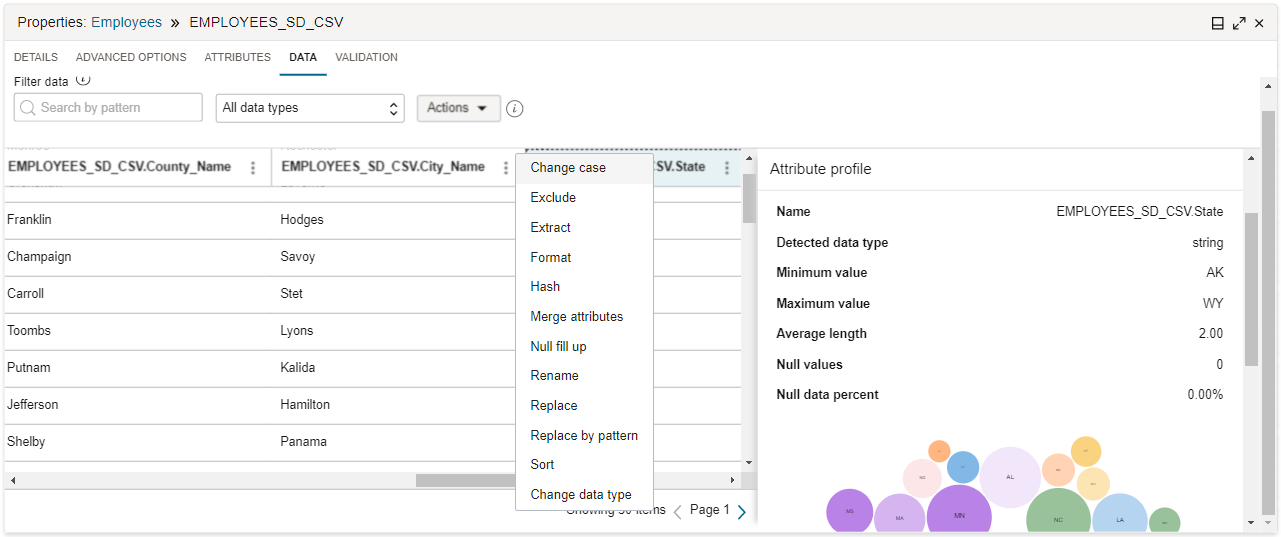
On the Data tab, you can apply transformations on a single attribute, or you can filter the attributes by a name pattern or data type, and then apply transformations on a group of attributes. You can also preview the results of data transformations in the Data tab, without having to run the entire data flow.
In Data Integration, you use the Map tab to describe the flow of data from source attributes to target attributes.
A target can be an existing data entity or a new data entity. In a data flow, the Map tab is only applicable to a target operator for an existing data entity. For existing target data entities, the source attributes and any customized attributes coming from upstream operations are mapped to attributes on the target.
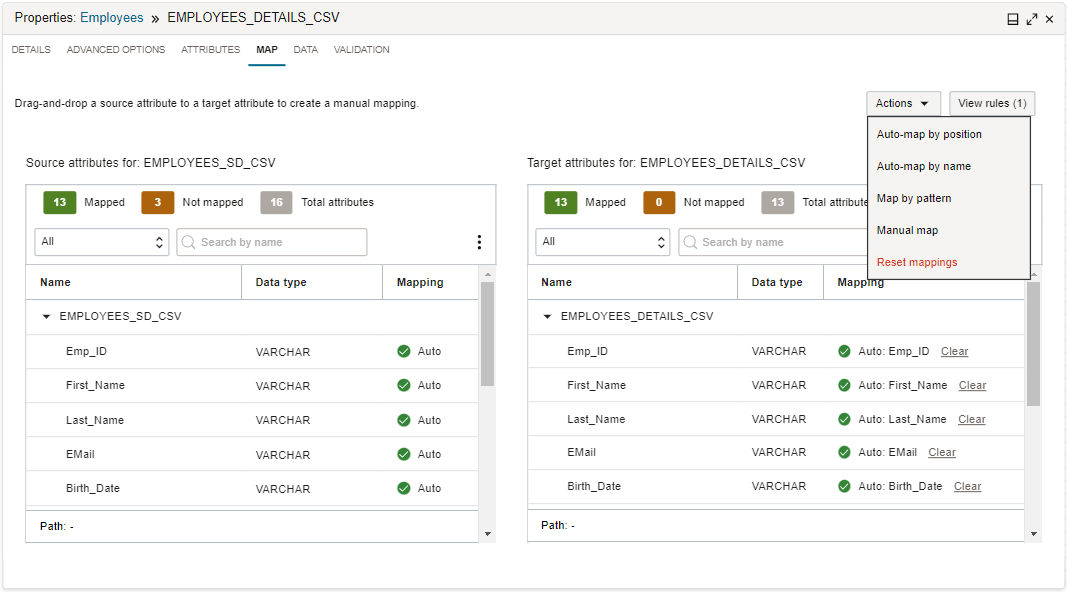
You can choose to use automatic mapping or manual map. For automatic mapping, Data Integration can map incoming attributes to target attributes with the same name, or according to their position in the attribute lists. For manual map, you can drag an incoming attribute from the source list to an attribute in the target list to create a mapping. Alternatively, you can use the Map Attribute dialog to create a mapping by selecting a source attribute and a target attribute. You can also use a source attribute pattern and target attribute pattern to create the mapping.
When you select the Create new data entity checkbox on a target operator, the Map tab is not available. Data Integration uses the incoming source attributes to create the table or file structure with a one to one mapping.
Using the Designer Interface
The Data Integration designer lets you use a graphical user interface to build a data integration flow.
You also use a similar designer to build a pipeline.
The main areas of the designer are:

Tools to help you navigate a data flow or pipeline on the canvas include:
- View: Select this menu to choose to open or close the Properties, Operators, Validation, and Parameters panels.
- Zoom in: Lets you zoom in on the design.
- Zoom out: Lets you zoom out to view more of the design.
- Reset Zoom: Returns to the default view of the design.
- Grid Guide: Toggles the grid guides on and off.
- Auto Layout: Arranges the operators on the canvas.
- Delete: Removes the selected operator from the canvas.
- Undo: Removes the last action performed.
- Redo: Performs the last action if you previously selected Undo.
You can undo and redo the following types of actions:
- Adding and deleting an operator
- Adding and deleting connections between operators
- Changing the position of an operator on the canvas
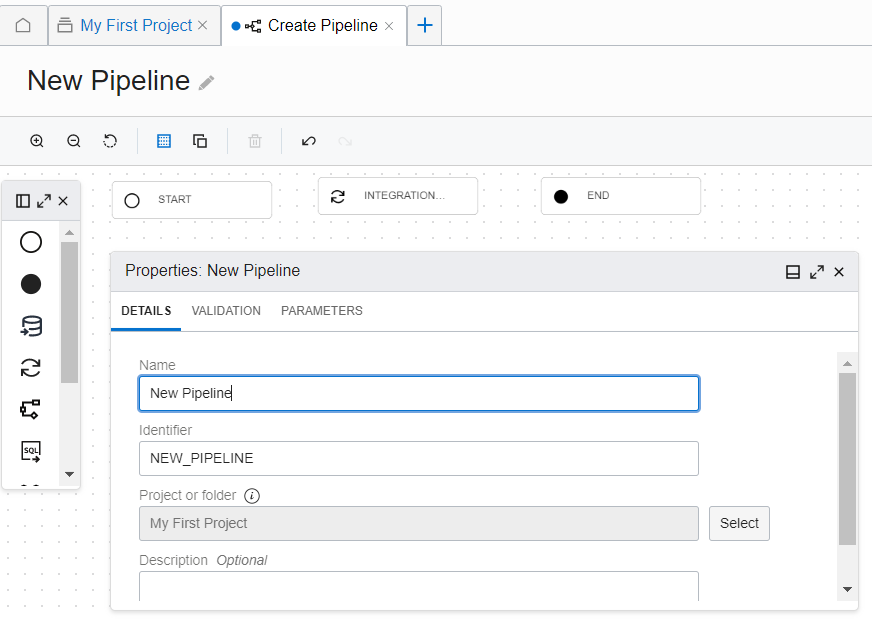
The canvas is the main work area, where you design the data flow or pipeline .
Drag objects from the Operators panel onto the canvas to begin.
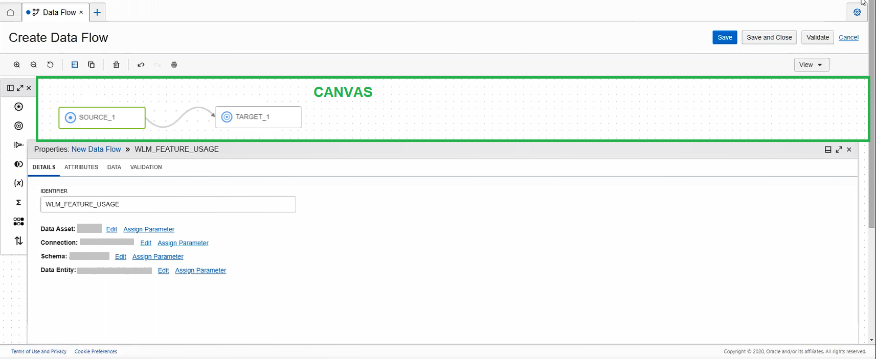
You start with a blank canvas for a data flow. For a data flow to be valid, you must have at least one source and one target defined.
For a pipeline, you start with a canvas that has a start operator and an end operator. The pipeline design must include at least one task operator to be valid.
To connect two operators, hover over an operator until you see the connector (small circle) on the right side of the operator. Then drag the connector to the operator you want to connect to. A connection is valid when a line connects the operators after you drop the connector.
To insert an operator between two connected operators, right-click the connection line and use the Insert menu.
To delete a connection, you can right-click a line and select Delete.
To duplicate a source, target, or expression operator, right-click the operator icon and select Duplicate.
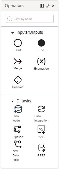
The Operators panel displays the operators you can add to a data flow or pipeline.
Drag operators from the Operators panel onto the canvas to design the data flow or pipeline. Each operator has a different set of properties that you configure using the Properties panel.
For a data flow, you can add input, output, and shaping operators.
For a pipeline, you add input, output, and task operators to construct a sequence.
About the Operators
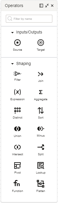
The following operators are available for you to use in a data flow:
- Inputs/Outputs
-
- Source: Represents a source data entity that serves as an input in a data flow.
- Target: Represents a target data entity that serves as an output entity to store the transformed data.
- Shaping
-
- Filter: Selects certain attributes from the inbound port to continue downstream to the outbound port.
- Join: Links data from multiple sources. The types of joins supported are Inner, Right Outer, Left Outer, and Full Outer.
- Expression: Performs a transformation on a single row of data.
- Aggregate: Performs calculations such as sum or count on all or a group of rows.
- Distinct: Returns distinct rows with unique values.
- Sort: Performs sorting of data in ascending or descending order.
- Union: Performs a union operation on up to 10 source operators.
- Minus: Performs a minus operation on two sources and returns the rows that are present in one source but not present in the other.
- Intersect: Performs an intersect operation on two or more sources and returns the rows that are present in the connected sources.
- Split: Performs a split operation to divide one source of input data into two or more output ports based on split conditions.
- Pivot: Performs a transformation using aggregate function expressions and values of an attribute that's specified as the pivot key, resulting in multiple new attributes in the output.
- Lookup: Performs a query and then a transformation using a primary input source, a lookup input source, and a lookup condition.
- Function: Invokes an Oracle Cloud Infrastructure Oracle Function from within a data flow in Data Integration.
- Flatten: Performs unnesting of a complex file structure from the root to the hierarchical data type attribute that you select.
Learn more about Using Data Flow Operators.
- Inputs/Outputs
-
- Start: Represents the start of a pipeline. There is only one start operator in a pipeline. The start operator can have links to more than one task.
- End: Represents the end of a pipeline. There is only one end operator in a pipeline. The end operator can have links from more than one upstream node.
- Expression: Lets you create new, derivative fields in a pipeline, similar to an expression operator in a data flow.
- Merge: Performs a merge of tasks that run in parallel. The specified merge condition determines how to proceed with subsequent downstream operations.
- Decision: Lets you specify a pipeline branching flow by using a decision condition. Based on upstream outputs, the specified condition expression must evaluate to a Boolean value, which determines the subsequent downstream branching.
- Tasks
-
- Integration: Binds to an integration task.
- Data Loader: Binds to a data loader task.
- Pipeline: Binds to a pipeline task.
- SQL: Binds to a SQL task.
- OCI Data Flow: Binds to an application in Oracle Cloud Infrastructure Data Flow.
- REST: Binds to a REST task.
Working with the Operators Panel
To help you work more efficiently, you can dock the Operators panel to the left of the screen. You can expand the panel or minimize the panel to show only icons, by using the expand or shrink icon. You can also close the panel. If the panel is closed, you can open it from the View menu on the designer toolbar.
The Properties panel lets you configure the data flow or pipeline and its operators.
Use the Validation tab to validate the entire data flow or pipeline.
In the Parameters tab, you can view all the parameters defined at the data flow or pipeline level, including system-generated parameters. For user-defined parameters, you can delete parameters, and if applicable, edit the default values of parameters.
For a data flow, after you add an operator on the canvas, select the operator and use the Properties panel to configure the operator. You can:
- Specify the operator details such as the identifier, and configure operator-specific settings in the Details tab.
- View the operator inbound and outbound attributes in the Attributes tab.
- Map incoming attributes to attributes in the target data entity for a target operator in the Map tab.
- Preview a sampling of data in the Data tab.
- Validate the configuration of the operator in the Validation tab.
Similarly for a pipeline, after you add an operator on the canvas, select the operator and use the Properties panel to configure the operator. You can:
- Specify a name for the operator in the Details tab. For a merge operator, you specify a merge condition. For an expression operator, you add one or more expressions. For task operators, you select a task to bind to the operator, and specify when the task runs based on the run status of the upstream operator.
For all task operators, you can select design-time tasks from projects in the current workspace, and published tasks from any Application in the current workspace. With published REST tasks and OCI Data Flow tasks, you can also select a task from any Application in another workspace in the same compartment or another compartment.
- If applicable, specify task run options in the Configuration tab.
- If applicable, configure incoming parameters in the Configuration tab.
- View the outputs in the Output tab, which can be used as inputs for the next operator in the pipeline.
- If applicable, validate the configuration of the operator in the Validation tab.
Working with the Properties Panel
To help you work more efficiently, you can dock the Properties panel to the bottom of the screen. You can expand the panel or minimize the panel, by using the expand or shrink icon. You can also close the panel. If the panel is closed, you can open it from the View menu on the designer toolbar.
More about tabs in the Properties panel
When you click the canvas and no operator is selected, the Properties panel displays the details of the data flow or pipeline .
When you select different operators on the canvas, the Properties panel displays the properties of the operator in focus. You can view, configure, and transform data as it flows through the operator using the following tabs in the Properties panel:
- Details
-
You can name an operator using the Identifier field in the Details tab. For source and target operators, you can also select the data asset, connection, schema, and the data entity. If you select Autonomous AI Lakehouse or Autonomous AI Transaction Processing as the data asset, the option to select the staging location is enabled. The staging location lets you select the Object Storage bucket to stage the data before it moves into the target.
You can select the data asset, connection, schema, and the data entity only in the order as displayed under the Details tab. For example, you can select the connection only after you select the data asset. The select option for schema is enabled only after you select the connection, and so on. A selection can be done only based on the parent-child relation inherited from the preceding selection. After making a selection, the edit option is enabled.
You can assign parameters to various details of each operator so that these details are not bound to the compiled code when you publish the data integration flow. See Using Parameters in Data Flows and Using Parameters in Pipelines.
For shaping operators, you can create the conditions or expressions to apply to the data as it passes through the operator.
For a pipeline, you use the Details tab to provide a name for the pipeline or the selected operator. For task operators, you also specify the task to use.
- Attributes
-
The Attributes tab appears only for a data flow.
From the menu, select to view the incoming attributes linked to the operator on the left side in the canvas, or the output attributes going into the next operator linked to it on the right side.
Selecting the filter icon in the Name column displays the filter field. Enter a simple regex pattern or wildcards (such as
?and*) in the filter field to filter the attributes by name pattern. The field is case insensitive. Selecting the filter icon in the Type column displays the type menu. Use the menu to select the type filter. You can apply only one name pattern filter, but multiple type filters at a time. For example, to filter by the name pattern *_CODE and by the type numeric or varchar, you apply one name pattern filter (*_CODE) and two type filters (numeric, varchar).You can then select attributes to exclude, or select the filter-applied attributes to exclude. Use the Actions menu to choose to exclude by selection or exclude by applied filters. Chosen exclude rules are added to the Rules panel. The applied filters appear at the top of the attributes list. Use the Clear All option to reset the applied filters.
Select View Rules to open the Rules panel, and see all rules applied to the data entity. You can also view rules from the success message that appears at the top-right corner, after applying the rules. By default, the first rule in the Rules panel includes everything. You can further apply actions to each rule, such as reordering it in the list or deleting it.
- Map
-
The Map tab appears only for a data flow.
This tab appears only for a target operator. It lets you map the inbound attributes to the target data entity's attributes, either mapping by position, name, pattern, or direct map. You can also use automatic mapping, which maps by name, or remove the mappings.
- Data
-
The Data tab appears only for a data flow.
Access the Data tab to preview a sampling of data to see how a transformation rule affects the data as it passes through the operator.
Note
Ensure that you have the data asset, connection, schema, and data entity configured before you access the Data tab.You can filter data by a name pattern or data type, and apply an exclude rule to the filtered data or do transformations in bulk using the Actions menu. To filter data by a name pattern, enter a simple regex pattern with wildcards (such as
?and*) in the Search by pattern field. To filter data by a data type, select the type from the menu. Transformations cannot be applied for a target operator as the data is read-only.As you add and remove rules and transformations, the data sampling is updated to reflect these changes. Learn more about Data Transformations.
- Configuration
-
The Configuration tab appears only for a pipeline. If available for a task, you can reconfigure the parameter values that are associated with the task or the underlying data flow, if applicable.
- Output
-
The Output tab appears only for a pipeline.
You can view the list of outputs that can be used as inputs to connected operators in the pipeline.
- Validation
- Use the Validation tab to check that the operator is configured correctly, to prevent errors later when you run the data flow or the pipeline. For example, if you forget to assign inbound or outbound operators, then warnings messages appear in the Validation panel. When you select a message in the Validation panel, it brings that operator into focus so that you can address the error or warning.
The Parameters panel displays the parameters used in a data flow or pipeline.
You can also delete a parameter from the Parameters panel.
You can view all the error and warning messages for a data flow or pipeline in the Global validation panel.
On the canvas toolbar, select Validate to check and debug the data flow before using the data flow in an integration task. Similarly, check and debug the pipeline before using it in a pipeline task. The Global validation panel opens and displays error and warning messages for you to address. Selecting a message brings you to the operator that produced the error or warning message.