Flex Network Scenarios
This topic presents practical usage scenarios for Private Cloud Appliance Flex networks. Both Hub mode and Edge mode are taken into account.
Configuring a Flex Network in Edge Mode with Connection to Oracle Exadata
This example describes how to create a Flex network in Edge mode between Private Cloud Appliance and an Oracle Exadata.
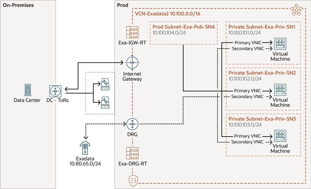
This example, as shown in the diagram, creates a Flex network with a VCN that contains 3 virtual machines each connected to a private subnet, and also connected to one public subnet. The private subnets are routed through a dynamic routing gateway attached to the VCN, out to Exadata, which provides the compute instances access to Exadata. This example also includes a public subnet, accessible by the compute instances. This public subnet can be configured with an internet gateway to reach the data center ToR switches.
Before You Begin
-
Identify which physical ports on the Private Cloud Appliance spine switches will connect to the external system. See Valid Port Configurations in Creating and Enabling a Flex Network.
-
Identify the on-premises network subnet and reserve three IP addresses for the spine switches.
Configuration Procedure
-
Create the Flex network from the Service Enclave. See Adding the New Flex Network.
To create a Flex network, at a minimum, you need the following parameters:
Parameter
Example Value
cidr
10.nn.nn.0/24
spine1Ip
10.nn.nn.101
spine2Ip
10.nn.nn.102
spineVip
10.nn.nn.1
vlan
2100
ports
7/1,7/2
advertiseNetwork
True
Example:
PCA-ADMIN> create flexNetwork cidr=10.nn.nn.0/24 \
spine1Ip=10.nn.nn.101 spine2Ip=10.nn.nn.102 spinevip=10.nn.nn.1 \
vlan=2100 ports=7/1 advertiseNetwork=true
Status: Success
JobId: 165f366-64c0-495e-sab1-34s8824b0da

PCA-ADMIN> list flexNetwork
Data:
  id                                  Vlan   CIDR            Spine1Ip     Spine2Ip      SpineVip    Ports
  --                                  ----   ----            --------     --------      --------    -----
  ocid1.cccexadata2.oc1.<unique_id> 2100  10.nn.nn.0/24   10.nn.nn.101  10.nn.nn.102  10.nn.nn.1  7/1,7/2
Note the OCID of the Flex network. You need this OCID to enable the Flex network in step 5.
-
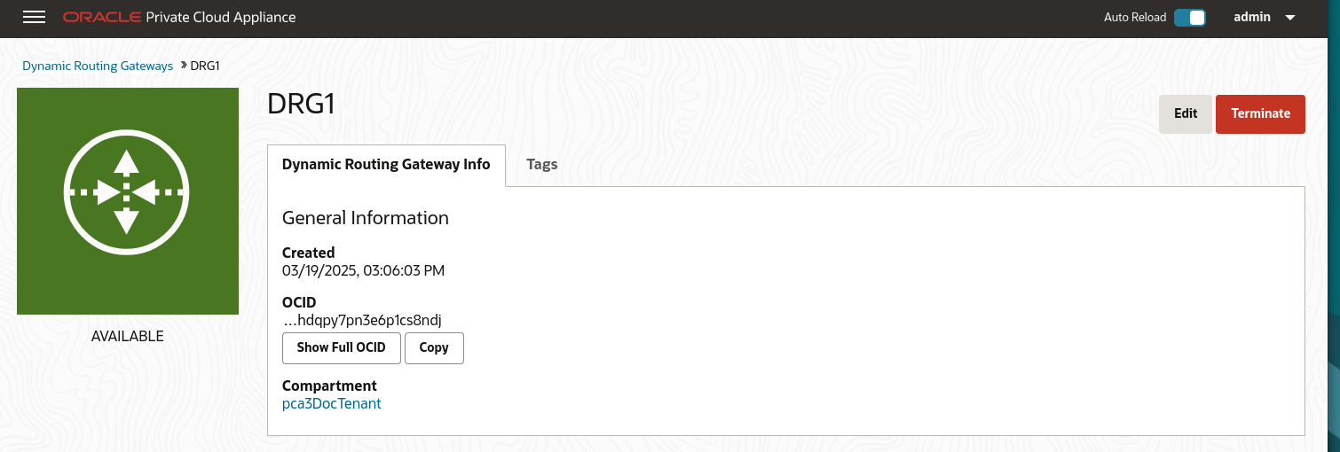
From the Compute Enclave, create a dynamic routing gateway (DRG) to provide a way for compute instances to access the external system. See Creating a Dynamic Routing Gateway.
-
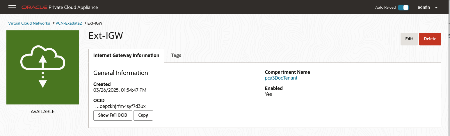
From the Compute Enclave, create an Internet Gateway (IGW) to provide a way for compute instances to access the data center switches. See Providing Public Access through an Internet Gateway.
-
From the Compute Enclave, create VCNs, and Subnets. See Managing VCNs and Subnets.
-
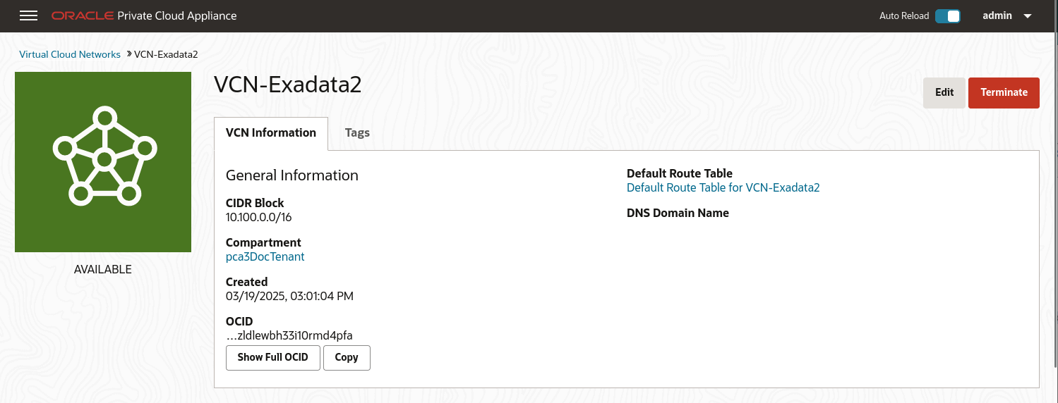
Create a VCN for use by the Flex network. In the Compute Web UI, create a VCN. Choose a compartment, a name for the VCN, then assign a CIDR block that meets your needs.
-
Create subnets within the VCN. Navigate to the VCN in the Compute Web UI, and click Create Subnet. Name the subnet, chose the compartment, and assign a CIDR block within the CIDR block range of the VCN. Next select private or public subnet, then click Create Subnet.
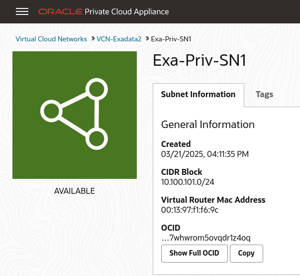
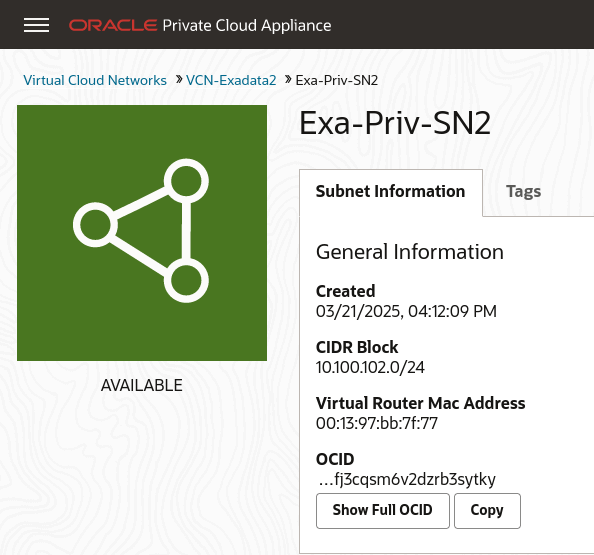
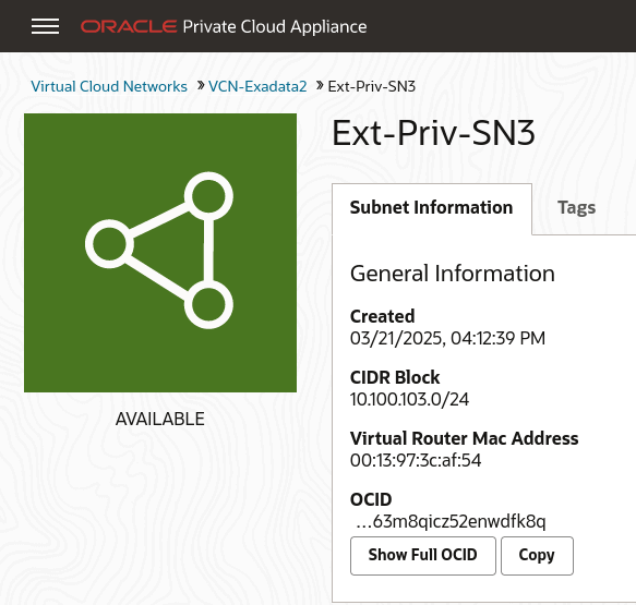
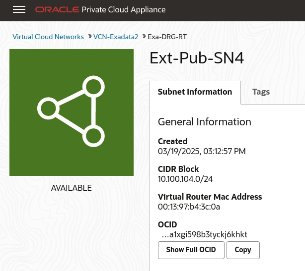
-
Note the OCID of each subnet, you need these OCIDs to enable communication between the compute instances and the Flex network in step 5 of this procedure.
-
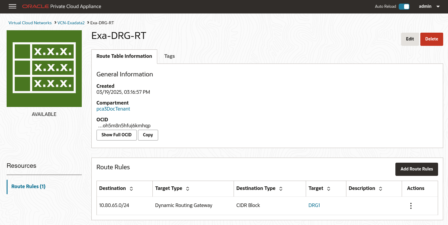
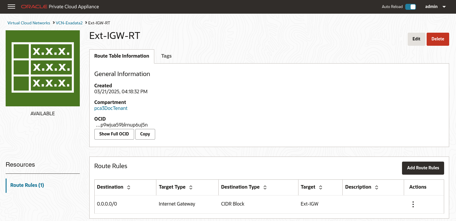
Create Route Tables in the VCN. Route tables are required to send traffic outside the VCN.
Navigate to the VCN in the Compute Web UI, select Route Tables in the Resources menu. Click Create Route Table, type a name for the Route Table and click Create Route Table.
Then create any associated route rules by clicking Add Route Rules and entering a target and the destination CIDR block.
This example shows a route table that directs network traffic for the DRG, and a route table that directs network traffic for the internet gateway.
-
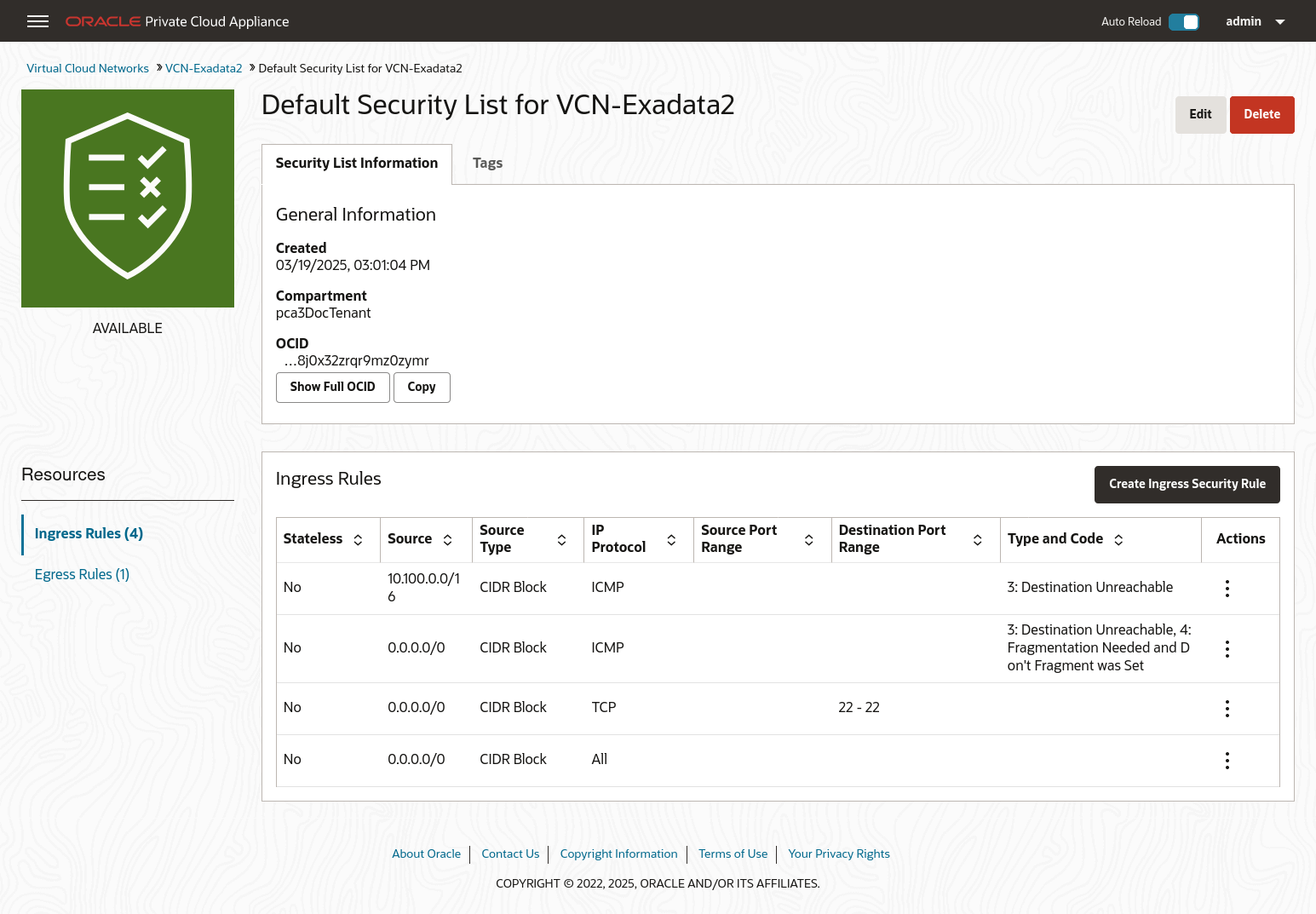
Create Security Lists to enable ingress traffic. See Controlling Traffic with Security Lists.
-
-
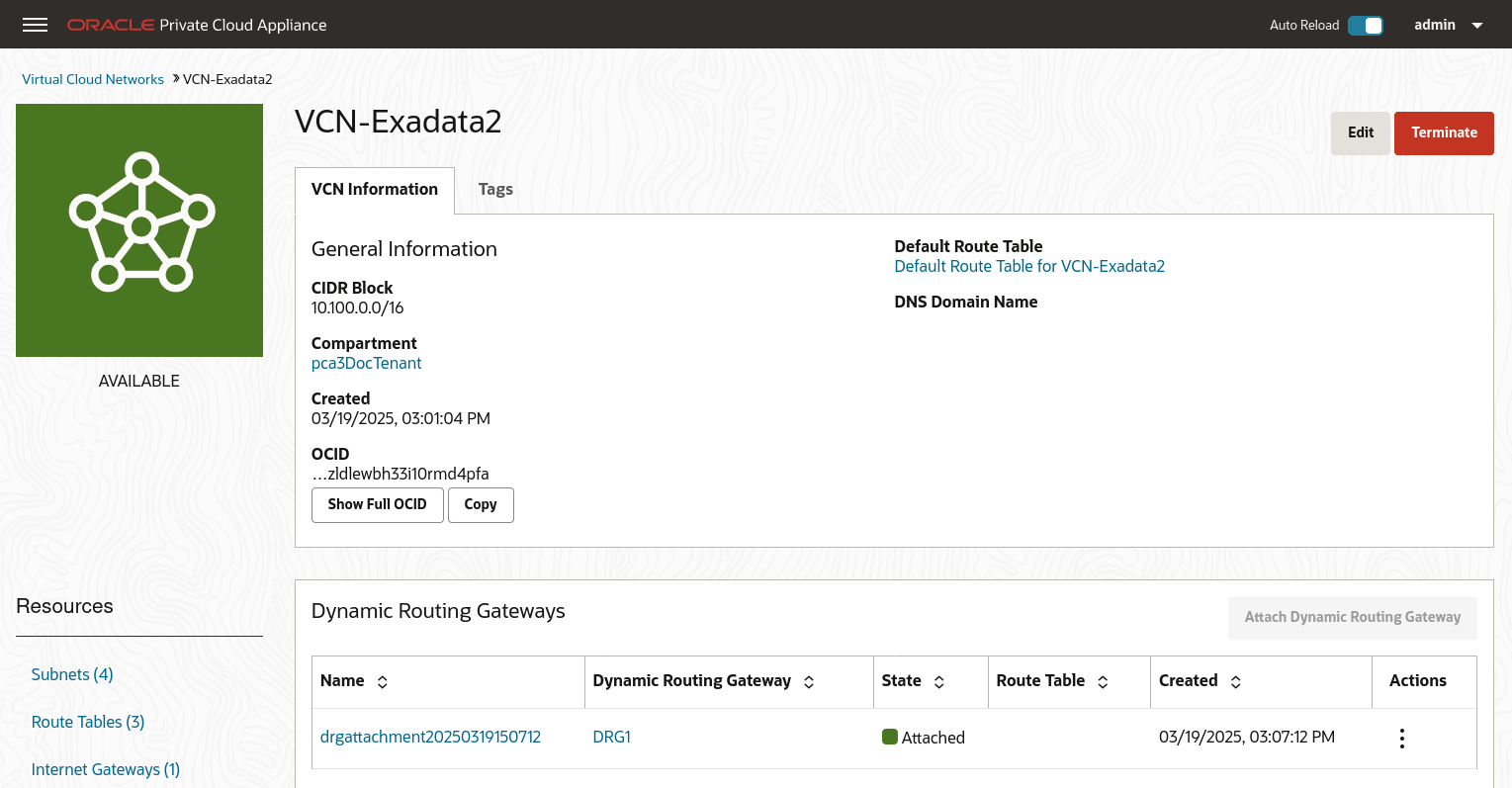
From the Compute Enclave, create DRG-attachments to enable the VCN to use the DRG. See Attaching VCNs to a Dynamic Routing Gateway.
From the VCN page, select Dynamic Routing Gateway from the left menu, then click Attach Dynamic Routing Gateway. Select the appropriate tenancy, then choose the DRG you want to attach from the drop down list and click Attach Dynamic Routing Gateway.
-
From the Service CLI, enable communication between the Flex network and the VM subnets.
PCA-ADMIN> flexNetworkEnableAccess flexNetworkId=ocid1.exadata.unique_id \ subnetId=ocid1.subnet.unique_id Status: Success -
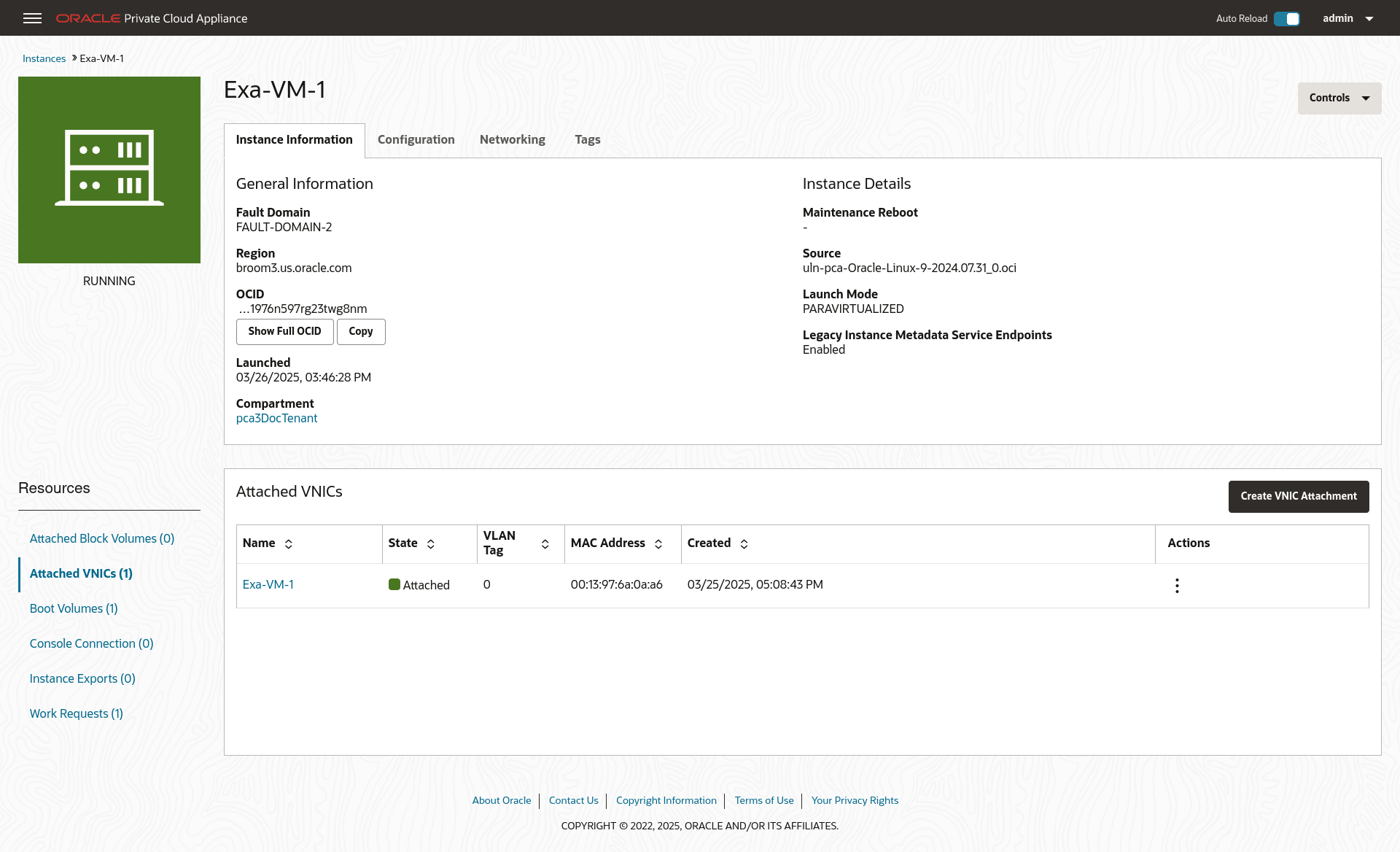
Create compute instances in the subnets and configure their access. See Working with Instances.
For this example, each private subnet is configured with 2 VNICs: a primary and a secondary. Configure primary VNICs to attach to the public subnet, and secondary VNICs to attach to the DRG.
When creating an instance, select the VCN and then the subnet. For the public compute instance, assign a public IP address.
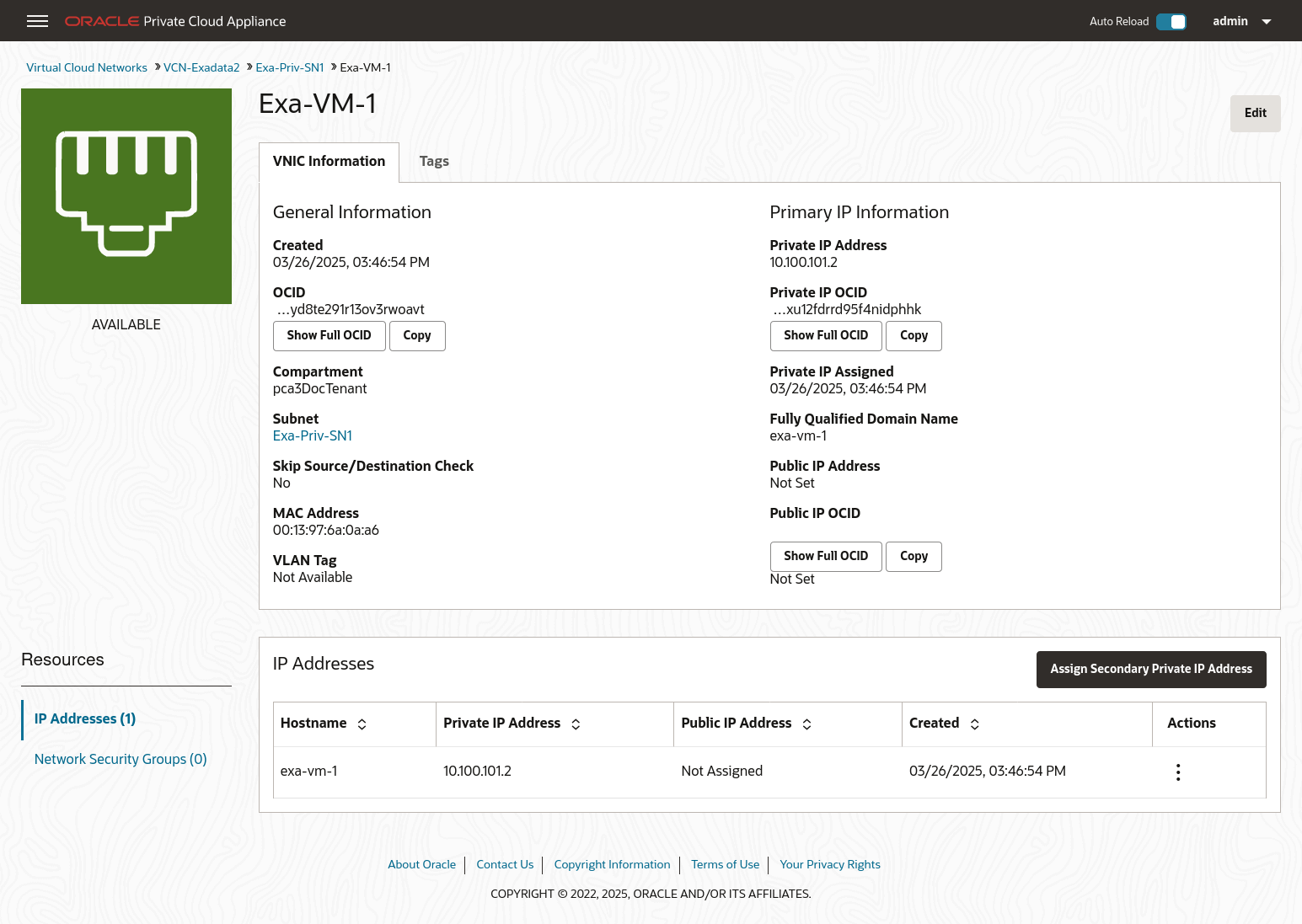
From the Compute Instance page, select the instance. From the Resources menu select Attached VNICs. You will see the primary VNIC. To create the secondary VNIC, click Create VNIC Attachment. Select the VCN and a subnet, and assign. See Creating and Attaching a Secondary VNIC.
Create primary and secondary VNICs for each instance such that the primary VNIC attaches to the public subnet, and the secondary VNIC attaches to the DRG.
-
Verify connectivity between the compute instances and the external system.