Creating an Enterprise Process Model for Purchase Orders
A Process Designer or Business Analyst can create the Purchase Order process model in the Enterprise Process Manager. To create a process model, you must select a template provided by the system and configure the source of data for metrics, measurements, and KPIs, and define certain aggregations or calculations (sum, average, and so on) for those metrics. You can then save your configurations as a process UDO.
To create a new enterprise process:
- Access the JD Edwards EnterpriseOne application.
- From the user drop-down list, click Manage Content, and select
Processes.
The system displays the Create Process window.
Note: The Create Process window is only displayed when you are creating an enterprise process for the first time. After creating a process, when you click Processes again, the system displays the previously created process layout along with the template used for its creation and the Enterprise Process Manager options.If you want to create a new process, in the Enterprise Process Manager window, click the Name drop-down list and select Create.
- From the Import Process Template drop-down list, select JDE TMPL Procure to Pay template.
- Click OK.
- The Order Type and Line Type fields, along with their default values,
are displayed in the Create Process window. You can edit the values or accept
the default values. Note: You must set up the order activity rules for the order type and line type combination. The system processes an order line based on the order activity rules that you set up for this combination.
Select the Start Status from the drop-down list. The system displays the available nodes for Procure to Pay template in this drop-down list. The value you select in this field becomes the first (start) node in the automatically generated process model. The Start Status value defaults to
Enter
                        Purchase Order (220)
. - Click OK. The Main Module tab is displayed in the Enterprise Process Manager window,
where you can see the automatically generated enterprise process diagram based on
the values defined in the Create Process window and the order activity rules that
you set.
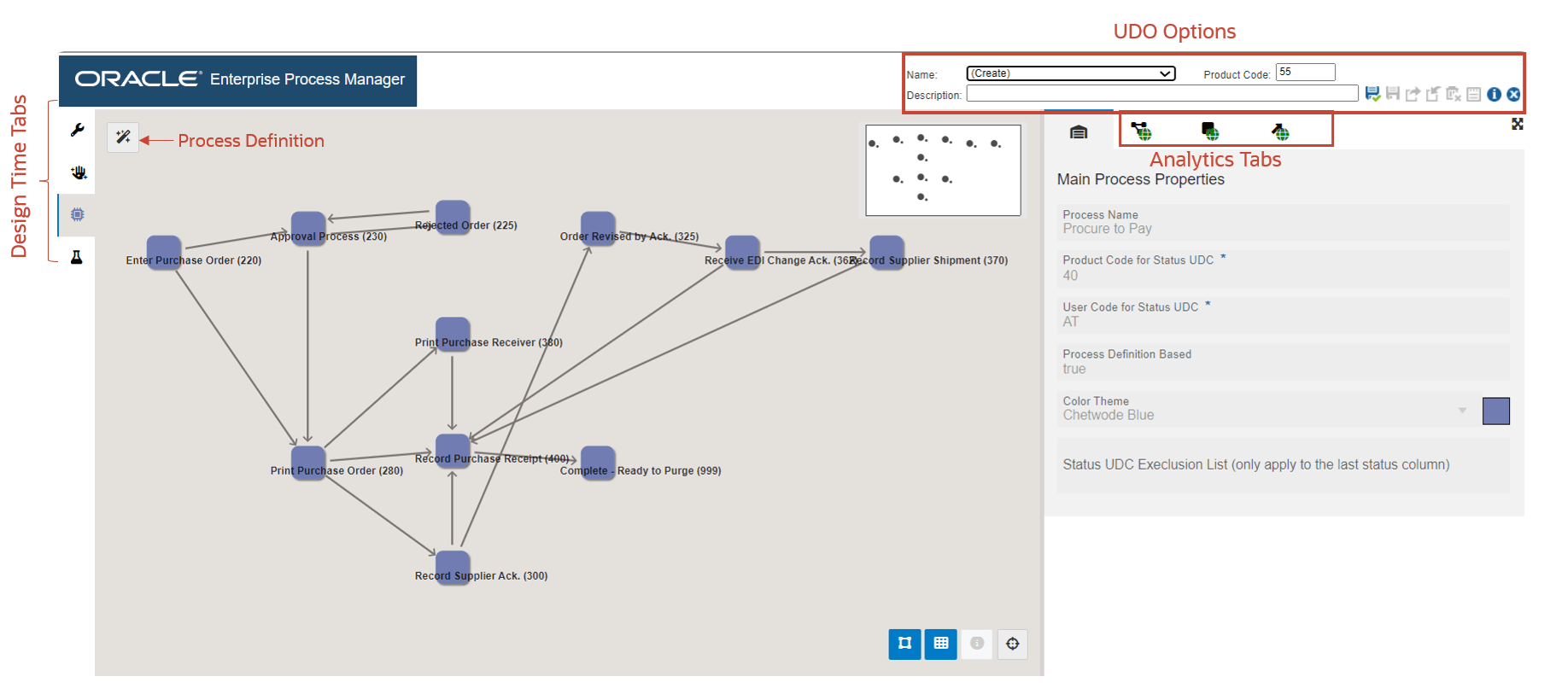
The enterprise process diagram displays nodes and the links between the nodes. The nodes represent the tasks in the process template and the links represent the connection between the nodes.
-
Click the Open Process Definition icon (next to Design Option) to review the settings in the read-only tab with Basic Configuration, Filter Configuration, and Status Configuration details.
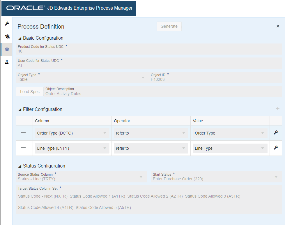
The Process Definition window opens. You can view the Basic Configuration, Filter Configuration, and Status Configuration details based on the values defined in the Create Process window and the order activity rules that you have set. These configurations are used to build the nodes and links and to automatically generate the process model.
- The Basic Configuration section displays the UDC - Activity/Status Codes (40/AT) and the table that the system uses to generate the template - Order Activity Rules table (F40203).
- The Filter Configuration section displays the columns based on which the data is filtered. The system filters the data based on Order Type and Line Type values for the Procure to Pay process modeler.
- The Status Configuration section displays the Source Status Column, Start Status, and Target Status Column Set.