Viewing a Routing Definition in Graphical Format
The Integration Broker Routing Graphic page (IB_IMAGETEST2) displays routing definition data in graphical format.
This example illustrates the Integration Broker Routing Graphic page. The example shows a synchronous routing definition, QE_PO_SYNC, in graphical format.
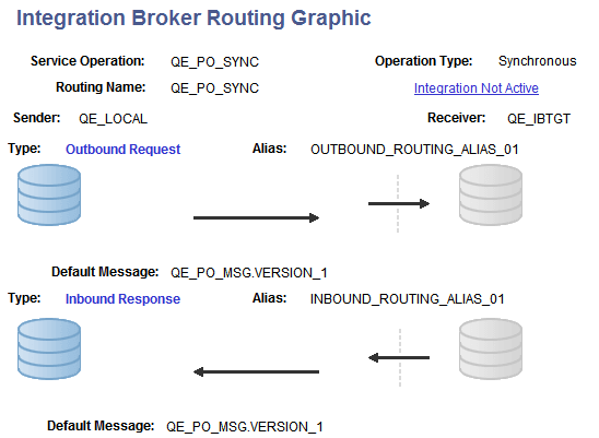
The example shows that the service operation QE_PO_SYNC is associated with the routing. It also shows that the routing type is Synchronous.
The sending node is QE_LOCAL, and the node is depicted graphically by the cylinders on the left side of the example. The receiving node is QE_IBTGT and is depicted graphically by the cylinders on the right side of the example.
The example shows the outbound request from the node QE_LOCAL to the node QE_IBTGT has a routing alias of OUTBOUND_ROUTING_ALIAS.V1. It also shows that the outbound default message associated with the routing is QE_PO_MSG.VERSION_1.
When the node QE_IBTGT sends back its response, it has a routing alias of INBOUND_ROUTING_ALIAS.V1 and the message associated with the response is QE_PO_MSG.VERSION_1.
The dotted line depicts the integration gateway, and depending on the arrow direction shows the service operation leaving or entering the gateway.
Note in the example that an Integration Not Active link displays at the top right of the page. This indicates that one or more pieces of metadata associated with the integration is not active. Click the link to view and activate the data.