Flow Charts
Actions and PeopleCode events can occur in various sequences within the Component Processor’s flow of execution. Flow charts represent each sequence. In a flow chart, different shapes and colors represent different concepts.
| Term | Definition |
|---|---|
|
|
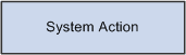
Blue rectangles represent actions taken by the system. |
| Term | Definition |
|---|---|
|
|
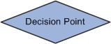
Dark rhomboids represent branches (decision points) in the logic. |
| Term | Definition |
|---|---|
|
|
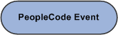
Dark ellipses represent PeopleCode events. |
| Term | Definition |
|---|---|
|
|
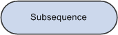
Light ellipses are subprocesses. |
Most processing sequences correspond to high-level component processor behaviors. However, two important subsequences occur only in the context of a larger sequence. These subsequences are:
-
Default processing, which occurs in a number of different contexts.
-
Row select processing, which most commonly occurs as a part of component build in any of the update action modes.
Row select processing also occurs when a ScrollSelect or related function is executed to load data into a scroll area.
See Component Processor Behavior, Default ProcessingDefault Processing.
Note:
Variations may occur in processing sequences, particularly when a PeopleCode function within a processing sequence initiates another processing sequence. For example, if a row of data is inserted or deleted programmatically during the component build sequence, a row insert or row delete sequence is initiated. Also note that components that run in deferred mode behave differently.