Understanding Diagram Elements
On the diagram window, the objects are represented distinctly, making them easy to identify.
The tables and views are represented with rectangles. The table rectangles have table names displayed on a yellow background, while the view and duality view rectangles have rounded corners and their names are shown on a green background.
The columns are prefixed with P, F, and U to indicate primary, foreign, and unique key constraints, respectively. An asterisk (*) denotes a mandatory column. Optional foreign keys are represented by dashed lines, while mandatory foreign keys are represented by solid lines.
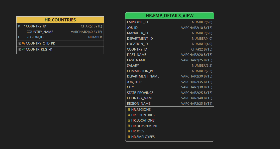
Description of the illustration table_view_rectangles.png
When you click the expand button next to a constraint, it shows the columns that are tied to that specific constraint, helping you understand the structure and relationships in the database schema.
Navigating Through Foreign Key Names
In the diagram window, hold the Alt key and click the foreign key name. The diagram will automatically center and highlight the referenced object. This action is available only if the referenced table or view is present on the current diagram.
In the Exported SVG (when viewed in a web browser), clicking the foreign key name will also center and display the referenced object, provided it exists in the diagram.