5.2 Two-Rack Cabling for X8M Racks
This section provides the cabling tables to connect two X8M racks together, both of which use RoCE Network Fabric.
Note:
The following conventions were used in the cabling notation for connecting multiple racks together.
-
The spine switch (also referred to as SS) is in U1 for all racks.
-
The leaf switches are referred to as Lower Leaf (LL) and Upper Leaf (UL).
-
The leaf switches are located as follows:
-
At rack unit 20 (U20) and 22 (U22) in Oracle Exadata X8M-2 or Storage Expansion Rack X8M-2
-
At rack unit 21 (U21) and rack unit 23 (U23) in Oracle Exadata X8M-8
-
-
The cable lengths shown in the following lists assume that the racks are adjacent to each other, the cables are routed through a raised floor, and there are no obstacles in the routing between the racks. If the racks are not adjacent, or use overhead cabling trays, then they may require longer cable lengths. Cable lengths up to 100 meters are supported.
-
Only optical cables (with additional transceivers) are supported for lengths greater than 5 meters.
-
For X8M-8 systems with three database servers and 11 storage servers only, you must adjust the following multi-rack cabling information. On such systems only, port 30 on the leaf switches is connected to a database server and is not used as an inter-switch link. Consequently, in the following tables, any connection to port number 30 on any leaf switch must instead connect to port number 34 on the same leaf switch. For example, R1-UL-P30 must change to R1-UL-P34, R1-LL-P30 must change to R1-LL-P34, and so on. These changes only apply to X8M-8 systems with three database servers and 11 storage servers.
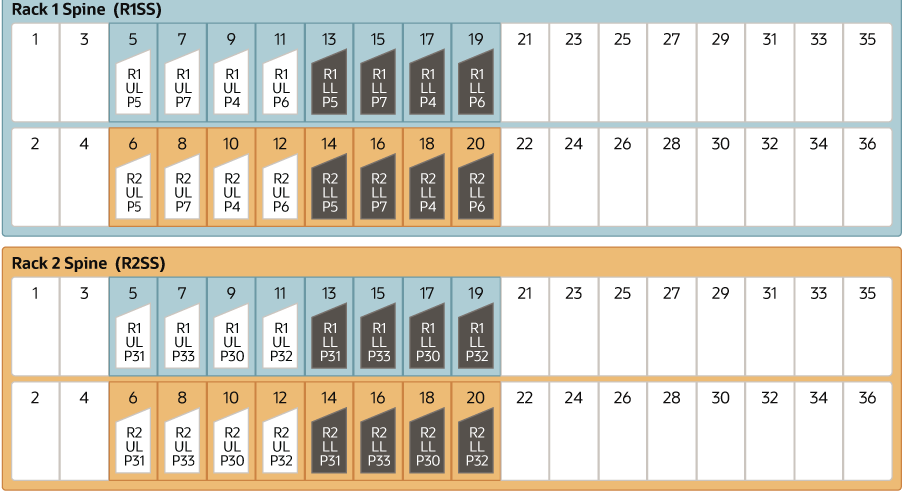
The following illustration shows the cable connections for the two spine switches (R1 SS and R2 SS) when cabling two racks together:
The following table describes the cable connections for the first spine switch (R1 SS) when cabling two racks together:
Table 5-1 Leaf Switch Connections for the First Rack in a Two-Rack System
| Leaf Switch | Connection | Cable Length |
|---|---|---|
|
R1 UL within Rack 1 |
R1-UL-P5 to R1-SS-P5 R1-UL-P7 to R1-SS-P7 R1-UL-P4 to R1-SS-P9 R1-UL-P6 to R1-SS-P11 |
3 meters |
|
R1 UL to Rack 2 |
R1-UL-P31 to R2-SS-P5 R1-UL-P33 to R2-SS-P7 R1-UL-P30 to R2-SS-P9 R1-UL-P32 to R2-SS-P11 |
5 meters |
|
R1 LL within Rack 1 |
R1-LL-P5 to R1-SS-P13 R1-LL-P7 to R1-SS-P15 R1-LL-P4 to R1-SS-P17 R1-LL-P6 to R1-SS-P19 |
3 meters |
|
R1 LL to Rack 2 |
R1-LL-P31 to R2-SS-P13 R1-LL-P33 to R2-SS-P15 R1-LL-P30 to R2-SS-P17 R1-LL-P32 to R2-SS-P19 |
5 meters |
The following table describes the cable connections for the second spine switch (R2 SS) when cabling two racks together:
Table 5-2 Leaf Switch Connections for the Second Rack in a Two-Rack System
| Leaf Switch | Connection | Cable Length |
|---|---|---|
|
R2 UL to Rack 1 |
R2-UL-P5 to R1-SS-P6 R2-UL-P7 to R1-SS-P8 R2-UL-P4 to R1-SS-P10 R2-UL-P6 to R1-SS-P12 |
5 meters |
|
R2 UL within Rack 2 |
R2-UL-P31 to R2-SS-P6 R2-UL-P33 to R2-SS-P8 R2-UL-P30 to R2-SS-P10 R2-UL-P32 to R2-SS-P12 |
3 meters |
|
R2 LL to Rack 1 |
R2-LL-P5 to R1-SS-P14 R2-LL-P7 to R1-SS-P16 R2-LL-P4 to R1-SS-P18 R2-LL-P6 to R1-SS-P20 |
5 meters |
|
R2 LL within Rack 2 |
R2-LL-P31 to R2-SS-P14 R2-LL-P33 to R2-SS-P16 R2-LL-P30 to R2-SS-P18 R2-LL-P32 to R2-SS-P20 |
3 meters |
Parent topic: Multi-Rack Cabling Tables for Oracle Exadata X8M Models
