4.1 Understanding Multi-Rack Cabling for X9M and Later Model Racks
Up to 14 racks (X9M and later models) can be cabled together without external RDMA Network Fabric switches.
To interconnect multiple racks, each rack must contain three RDMA Network Fabric switches.
Two of the switches, known as leaf switches, connect to all of the database servers and storage servers in the rack. The leaf switches are located as follows:
-
At rack unit 20 (U20) and 22 (U22) in 2-socket systems (Oracle Exadata X9M-2 and later models).
-
At rack unit 21 (U21) and rack unit 23 (U23) in 8-socket systems (Oracle Exadata X9M-8).
The third switch, known as the spine switch, interconnects the leaf switches in a multi-rack configuration. The spine switch is located at rack unit 1 (U1). If any rack does not include a spine switch, then order the expansion switch kit.
The procedures in this section assume the racks are adjacent to each other, standard routing in raised floor is used, and there are no obstacles in the raised floor. If these assumptions are not correct for your environment, then longer cables may be required for the connections.
Note:
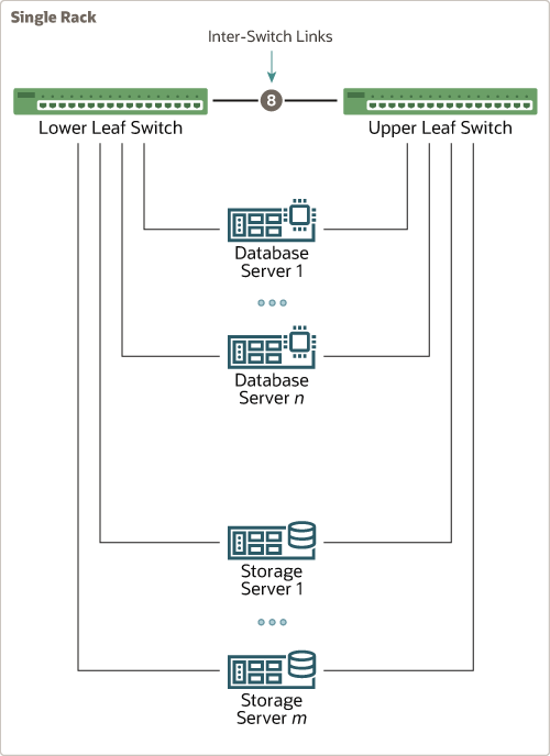
By default, Oracle Exadata Database Machine racks do not include spare cables or a third RoCE Network Fabric switch. To extend these racks, you must order the required cables and RoCE Network Fabric switch.The following diagram shows the default RDMA Network Fabric architecture for a single-rack system. Each rack has two leaf switches, with eight connections between the leaf switches. The database servers and storage servers are each connected to both leaf switches. Each server contains a dual-port RDMA Network Fabric card, with port 1 connected to the lower leaf switch and port 2 connected to the upper leaf switch.
To connect up to 14 racks (X9M and later models) together, use the following general approach:
-
Remove the eight existing inter-switch connections between the leaf switches on each rack.
-
From each leaf switch, evenly distribute 14 connections to the spine switches in all of the interconnected racks.
The 14 connections use the 8 ports that were previously used for the inter-switch connections and 6 additional free ports on each leaf switch.
Note:
For X9M-8 systems with three database servers and 11 storage servers only, the database servers and storage server require 23 leaf switch ports, which leaves only 13 inter-switch links on each leaf switch. Consequently, these systems are limited to a maximum of 13 interconnected racks.
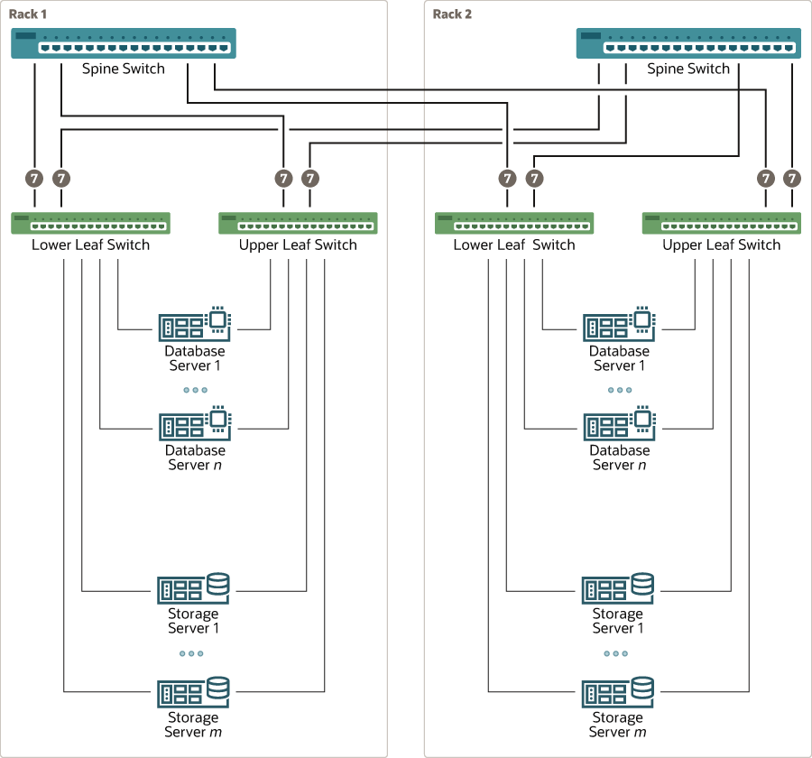
The resulting RoCE Network Fabric for a typical 2 rack system is illustrated in the following diagram:
As shown in the preceding diagram, every leaf switch has 7 connections to every spine switch. The leaf switches are not directly interconnected with other leaf switches, and the spine switches are not directly interconnected with each other.
As the number of racks increases, the inter-switch connections from every leaf switch are evenly distributed to all of spine switches.

