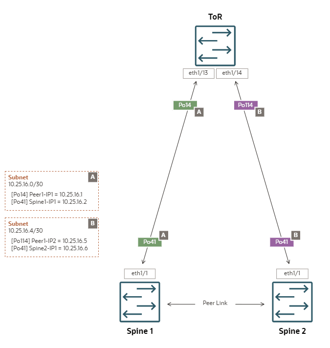
Triangle Topology with ECMP Static Routing
ECMP Triangle enables peering with a single data center router or switch.
Configuration Properties
-
Triangle topology – both spine switches are connected to a single data center switch
-
Static routing – all egress traffic from an uplink goes through a single gateway IP configured on its peer network device in the data center
-
ECMP – bandwidth optimization across multiple redundant links or paths
-
Separate /30 subnets – each uplink connects one spine switch port channel to one data center switch port channel in a /30 subnet
Topology Highlights
-
All uplinks are configured as LACP/active port channels with rate=fast
-
Port channel Po41 represents the set of links configured on both spine switches. Port channels Po14 and Po114 represent the corresponding sets of links configured on the ToR switch.
-
ToR switch ports connecting to the spine switches must be set up in access mode. Spanning tree protocol must be disabled.
-
Requires 2 unique subnets: a /30 subnet size is recommended, but /31 is possible if the ToR switch supports it.
-
Equal cost static routes to the ToR switch are set up automatically.
-
Egress traffic can hash to any of the 2 uplinks.
-
It is NOT possible to isolate specific VCN/VM egress traffic through one particular uplink.
-

Spine Switch Configuration Details
-
Spine Switch 1
interface port-channel41
  no shutdown
  mtu 9216
  ip address 10.25.16.2/30
  no ipv6 redirects
  ip proxy-arp
  ip nat outside

ip route 0.0.0.0/0 po41 10.25.16.1 20
ip route 0.0.0.0/0 po41 10.25.16.5 100
-
Spine Switch 2
interface port-channel41
  no shutdown
  mtu 9216
  ip address 10.25.16.6/30
  no ipv6 redirects
  ip proxy-arp
  ip nat outside

ip route 0.0.0.0/0 po41 10.25.16.5 20
ip route 0.0.0.0/0 po41 10.25.16.1 100