1 About Exadata Server X10M

This section includes the server component overview.

The Exadata Server X10M is a (1) or (2) processor socket, AMD® EPYC E5 Genoaâ„¢ SP5 processor-based, 2U rackmount server. The X10M is available with either a 4-Drive backplane [1] that supports up to four high performance NVMe drives or a 12-Drive backplane [2] that supports up to twelve high capacity SAS-3 drives.
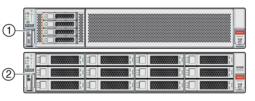
Exadata Server X10M chassis with four 2.5-inch or twelve 3.5-inch front panel drive bays.

The X10M 4-Drive backplane configuration is available with either a 9-slot PCIe card back panel or a Full Height PCIe card capable back panel configuration. The X10M 12-Drive backplane configuration is available with a 9-slot PCIe card back panel. The 9-slot PCIe card back panel server configuration supports (2) internal M.2 NVMe SSD modules.

Note:

Always update the server with the latest firmware, drivers, and other hardware-related software by downloading the latest software release package when you first receive the server, and for every new software release. For information about the software release packages and how to download the software, refer to Getting Firmware and Software.

These sections describe server controls, connectors, status indicators, system components, and replaceable components.

Product Description

The system supports these components and configurations.

Exadata Server X10M is an enterprise-class, two rack unit (2U) server that supports multiple configurations. Each configuration uses the same server but is provisioned differently. Some supported features are specific to individual configurations, while other features are common across configurations. Front and back panel configurations can include Exadata Server X10M provisioned with:

  • NVMe storage drives: 4-Drive bay front panel, either 9-slot PCIe card back panel or Full Height PCIe card capable back panel

  • SAS storage drives: 12-Drive bay front panel, 9-slot PCIe card back panel

Exadata Server X10M supports the following components:

Feature Exadata Server X10M System Components

System chassis

2U chassis

Processor

One or two processors with twelve memory channels per processor, 12 DIMMs per processor. Up to two AMD EPYC 9004-series processors (P0 and P1) with the following capabilities are supported (factory installed):
  • AMD Genoa, 96-core, 9J14, 2.6/3.7 GHz, 400W processors, 384 MB L3 cache
  • AMD Genoa, 32-core, 9334, 2.7/3.9 GHz, 210W processors, 128 MB L3 cache

Memory

Server memory configurations can include the following:

Dual-processor systems support up to twenty-four DDR5 128-GB, 96-GB, 64-GB, and 32-GB RDIMMs, for a maximum of twelve per processor, with speeds up to 4800 MT/sec. Total supported memory is up to 2.3 TB.

  • 24 DDR5 128-GB RDIMMs 4800 MT/sec 3.0 TB
  • 24 DDR5 96-GB RDIMMs 4800 MT/sec 2.3 TB
  • 24 DDR5 64-GB RDIMMs 4800 MT/sec 1.5 TB
  • 24 DDR5 32-GB RDIMMs 4800 MT/sec 512 G

Single-processor systems support up to twelve DDR5 RDIMMs for a maximum of 128-GB, 96-GB, 64-GB, and 32-GB RDIMMs with speeds up to 4800 MT/sec. Total supported memory is up to 1.15 TB.

  • 12 DDR5 128-GB RDIMMs 4800 MT/sec 1.5 TB
  • 12 DDR5 96-GB RDIMMs 4800 MT/sec 1.15 TB
  • 12 DDR5 64-GB RDIMMs 4800 MT/sec 768 G
  • 12 DDR5 32-GB RDIMMs 4800 MT/sec 384 G

Storage Drives

Storage drive configuration can comprise either solid state drives (SSDs) or hard disk drives (HDDs). Exadata Server X10M front panel storage drive bays can be provisioned with:

  • NVM-Express (NVMe) solid-state drives (SSDs):

    Up to four 2.5-inch hot-pluggable PCIe Gen4 NVMe SSDs:

    • Oracle 13.6 TB (15.36 TB Max) TB 2.5-inch NVMe PCIe 4.0 SSD
    • Oracle max 7.68 TB (15.36 TB Max) v2 2.5-inch NVMe PCIe 4.0 SSD
    • Oracle max 3.84 TB (15.36 TB Max) v2 2.5-inch NVMe PCIe 4.0 SSDFoot 1

    Up to four Oracle 30.72 TB QLC 2.5-inch NVMe PCIe 4.0 SSDs

  • SAS storage drives: Up to twelve 3.5-inch hot-pluggable SAS-3 hard disk drives (HDDs)

  • Two hot-pluggable internal M.2 Gen3 NVMe SSDs

PCI Express (PCIe) slots

Exadata Server X10M 4-Drive backplane configuration:

  • 9-slot PCIe card back panel configurations support up to nine half height PCIe cards

  • Full-height PCIe card capable back panel configurations support half height PCIe cards or full-height PCIe cards.

Exadata Server X10M 12-Drive backplane configuration:

9-slot PCIe card back panel configurations support up to nine half height PCIe cards.

9-slot PCIe Configuration

9-slot PCIe Configuration

9-slot PCIe card back panel: Exadata Server X10M supports up to nine half-height PCIe cards. Up to nine PCIe Gen5 vertical card slots are supported when the low profile Add In Card (AIC) chassis is utilized.

Up to nine PCIe card Gen5 slots are supported in dual-processor systems.

  1. Slot 1 - PCIe5 x16 electrical interface
  2. Slot 2 - PCIe5 x16 electrical interface
  3. Slot 3 - PCIe5 x8 electrical interface
  4. Slot 4 - PCIe5 x8 electrical interface
  5. Slot 5 - PCIe5 x16 electrical interface
  6. Slot 6 - PCIe5 x8 electrical interface, x16 electrical interface with motherboard PCIe Flyover cable attached
  7. Slot 7 - PCIe5 x8 electrical interface with motherboard PCIe cable attachedFoot 2
  8. Slot 8 - PCIe5 x8 electrical interface
  9. Slot 9 - PCIe5 x8 electrical interface, x16 connector

Full Height PCIe Configuration

Full Height PCIe Configuration

Two Riser back panel: Up to two vertical PCIe Gen5 slots and up to four horizontal PCIe Gen 3 and PCIe Gen 4 cards are supported.

  1. Slot 1 - PCIe5 x16 electrical interface
  2. Slot 2 - PCIe4 x16 electrical interface full-height PCIe card
  3. Slot 3 - PCIe4 not used
  4. Slot 4 - PCIe3 x1 electrical interface, full-height PCIe card
  5. Slot 5 - PCIe5 x16 electrical interface
  6. Slot 6 - PCIe4 x8 electrical interface, x16 electrical interface with motherboard PCIe Flyover cable installed, full-height PCIe card
  7. Slot 7 - PCIe4 not used
  8. Slot 8 - PCIe3 x1 electrical interface, full-height PCIe card

PCIe Riser

Two CEM Risers: Supports a single-wide PCIe CEM compliant PCIe card.

PCIe cards

  • Up to eight Oracle Flash Accelerator F680 PCIe Cards: 6.8 TB, NVMe PCIe 4.0
  • Up to three Oracle Dual Port QSFP56 Bifurcated 2x50Gb Network Interface Cards (NICs)
  • Up to three Oracle Dual Port QSFP56 2x50Gb NICs
  • Up to three Oracle Dual Port CX6-LX 2x25Gb NICs (LP ADAPTER, DUAL SFP28 25GBE,CX6 LX,PCIE4 0x8)
  • Up to three Oracle Dual Port CX6-DX 2x100Gb NICs (LP ADAPTER, DUAL QSFP56 200GBE,CX-6 DX,PCIE4.0x16)
  • Up to three Oracle Dual Port CX7 2x200Gb NICs (Connect X-7 2x200Gbit/Sec PAM4 PCIe Gen5 X16, Ethernet NIC)
  • Up to two Pensando Ortano/Elba Server Adapters, DSC-200V, 2x200GbE, Dual QSFP56
  • Up to two HBAs, BROADCOM 9500-8e, 12GB SAS PCIe, 8 PORT, EXTERNAL
  • Up to two HBAs, BROADCOM 9500-16i, 12GB SAS PCIe, 16 PORT, INTERNAL
  • One Oracle Dual Port 100 Gb RoCE Adapter

Root-of-Trust card

One Root-of-Trust (RoT) card back panel slot

Power supplies

Two hot-swappable and highly-redundant 1400W power supplies (PS0 and PS1)

Cooling fans

Six hot-swappable fan modules (FM0-5), each containing a 60mm x 56mm counter-rotating dual motor fan for chassis cooling.

I/O ports

NET 0: One 1GbE 100/1000BASE-T RJ-45 Gigabit Ethernet (GbE) port, labeled NET 0

NET MGT: One 1GbE 100/1000BASE-T RJ-45 Oracle Integrated Lights Out Manager (ILOM) service processor (SP) network management Ethernet port

SER MGT: One RJ-45 serial management Ethernet port

USB port

One USB 3.1 port

Service processor (SP)

One server integrated service processor (SP) provides local or remote management capabilities with Oracle Integrated Lights Out Manager (ILOM), primarily for fan control and thermal monitoring. The service processor (SP) is based on the ASPEED AST2600 chip.

Management software

Oracle Integrated Lights Out Manager (ILOM) on the service processor (SP). Refer to Oracle ILOM Documentation.

Oracle Hardware Management Pack available as a standalone product for supported operating systems. Refer to Oracle Hardware Management Pack documentation at Servers Documentation - Systems Management.

BIOS Setup Utility Menus The server supports the Unified Extensible Firmware Interface (UEFI). UEFI provides an interface between system firmware and all supported operating systems. With UEFI BIOS Setup Utility, you can configure platform-specific information, and some of the run-time and boot-time characteristics of your system using a simple graphical interface.

If you are managing multiple servers, you can use Oracle Enterprise Manager Ops Center. For information about Ops Center, refer to Oracle Enterprise Manager Ops Center 12c Release 3.

Footnote 1 Connected to x2 PCIe Gen5 links for boot drives.

Footnote 2 If slot 6 is PCIe5 x16 electrical interface, slot 7 is not functional.

See System Specifications

Front Panel Components

The NVMe Storage Drive Configuration supports up to four NVMe storage drives. The SAS Storage Drive Configuration supports up to twelve SAS storage drives.

NVMe Storage Drive Configuration

Exadata Server X10M supports up to four 2.5-inch hot-pluggable PCIe Gen4 NVM-Express (NVMe) solid-state drives (SSDs) on the front panel.

Figure showing the front panel of the Exadata Server X10M provisioned with 4 NVMe storage drives.
Callout Description

1

Product Serial Number (PSN) label and Radio Frequency Identification (RFID) tag

2

Front LED Indicator Module (FIM)

3

Storage drive 0 NVMe

4

Storage drive 1 NVMe

5

Storage drive 2 NVMe

6

Storage drive 3 NVMe

7

Service Information QR Code

SAS Storage Drive Configuration

Exadata Server X10M supports up to twelve 3.5-inch hot-pluggable SAS-3 hard disk drives (HDDs) on the front panel.

Figure showing the front panel of the Exadata Server X10M provisioned with 12 SAS storage drives.
Callout Description

1

Product Serial Number (PSN) label and Radio Frequency Identification (RFID) tag

2

Front LED Indicator Module (FIM)

3

Storage drive 0 SAS HDD

4

Storage drive 1 SAS HDD

5

Storage drive 2 SAS HDD

6

Storage drive 3 SAS HDD

7

Storage drive 4 SAS HDD

8

Storage drive 5 SAS HDD

9

Storage drive 6 SAS HDD

10

Storage drive 7 SAS HDD

11

Storage drive 8 SAS HDD

12

Storage drive 9 SAS HDD

13

Storage drive 10 SAS HDD

14

Storage drive 11 SAS HDD

15

Service Information QR Code

Front LED Indicator Module

Exadata Server X10M NVMe Storage Drive and SAS Storage Drive configurations support a Front LED status indicator module (FIM) on the front panel.

Figure showing the front panel of server with Front LED indicator module.
Callout Description

1

Front LED Indicator Module (FIM)

2

Locate Button/LED: white

3

Fault-Service Action Required LED: amber

4

System OK LED: green

5

On/Standby button

6

TOP FAN Fault-Service Required LED for internal access Fan Modules: amber

7

REAR PS Fault-Service Required LED for back panel Power Supplies: amber

8

Overtemp Fault-Service Required LED: System Over Temperature Warning: amber

9

SP Service Processor OK LED: green

10

DO NOT SERVICE LED: white

Back Panel Components

The 9-slot PCIe half height card configuration supports up to nine half height PCIe cards. Using PCIe risers, the full height PCIe configuration supports up to four full height and two half height PCIe cards.

9-slot PCIe Card Configuration

Exadata Server X10M, in 9-slot PCIe card back panel half height PCIe configuration, supports up to nine vertically mounted half height PCIe cards.

Figure showing the back panel of Exadata Server X10M containing up to nine half height PCIe cards.
Callout Description

1

Power supply (PS1)

2

Power Supply 1 (PS1) status indicators: Fault-Service Required LED: amber; AC OK LED: green

3

Power Supply 1 (PS1) AC Power Inlet (AC1)

4

Power supply (PS0)

5

Power Supply (PS0) status indicators: Fault-Service Required LED: amber; AC OK LED: green

6

Power Supply (PS0) AC Power Inlet (AC0)

7

(Oracle internal use only) Dedicated Root-of-Trust (RoT) card slot

8

PCIe slot 1 (PCIe5, x16 electrical interface)

9

PCIe slot 2 (PCIe5, x16 electrical interface)

10

PCIe slot 3 (PCIe5, x8 electrical interface)

11

PCIe slot 4 (PCIe5, x8 electrical interface)

12

PCIe slot 5 (x16 electrical interface)

13

PCIe slot 6 (PCIe5, x8 electrical interface, x16 electrical interface with MB PCIe Flyover cable)

14

PCIe slot 7 (PCIe5, x8 electrical interface with PCIe Flyover cable)

15

PCIe slot 8 (PCIe5, x8 electrical interface)

16

PCIe slot 9 (PCIe5, x8 electrical interface, x16 electrical connector)

17

LOCATE: Server Locate Button/LED

18

SP: Reset service processor (SP). See Manually Resetting a Server's Service Processor.

19

NET 0: Network (NET) 1GbE 100/1000BASE-T RJ-45 Gigabit Ethernet (GbE) port

20

NET MGT: Oracle Integrated Lights Out Manager (ILOM) service processor (SP) network management (NET MGT) 1GbE RJ-45 100/1000BASE-T port

21

USB 3.1 connector

22

SYSTEM: Fault-Service Required: amber; System OK: green. See System status LEDs

23

SER MGT: Serial management (SER MGT) RJ-45 serial port

Single-processor systems: PCIe slots 1-4 are nonfunctional in single-processor systems.

Full Height PCIe Configuration

Exadata Server X10M, in full-height PCIe card capable back panel configuration, supports four full-height, full-width PCIe cards horizontally mounted in two PCIe risers, and two half-height, half-width PCIe cards vertically mounted in slots 1 and 5.

Figure showing the back panel of Exadata Server X10M containing two PCIe risers and up to six PCIe cards.
Callout Description

1

Power Supply (PS1)

2

Power Supply 1 (PS1) status indicators: Fault-Service Required LED: amber; AC OK LED: green

3

Power Supply 1 (PS1) AC Power Inlet (AC1)

4

Power Supply (PS0)

5

Power Supply 0 (PS0) status indicators: Fault-Service Required LED: amber; AC OK LED: green

6

Power Supply 0 (PS0) AC Power Inlet (AC0)

7

(Oracle internal use only) Dedicated Root-of-Trust (RoT) card slot

8

PCIe slot 1 (PCIe 5, x16 electrical interface)

9

PCIe slot 2 (PCIe 4, x16 electrical interface) Riser 2

10

PCIe slot 3 (Blank), Riser 2

11

PCIe slot 4 (PCIe 3, x16 electrical interface(1)) Riser 2 x16 connector, x1 Electrical Gen3, Riser 2

12

PCIe slot 5 (PCIe 5, x16 electrical interface)

13

PCIe slot 6 (PCIe 4, x16 electrical interface) Riser 6 x16 connector, x1 Electrical Gen3, Riser 6

14

PCIe slot 7 (Blank), Riser 6

15

PCIe slot 8 (PCIe 3, x16 electrical interface (1)) Riser 6

16

LOCATE: Server Locate Button/LED

17

SP: Reset service processor (SP). See Manually Resetting a Server's Service Processor.

18

NET 0: Network (NET) 1GbE 100/1000BASE-T RJ-45 Gigabit Ethernet (GbE) port

19

NET MGT: Oracle Integrated Lights Out Manager (ILOM) service processor (SP) network management (NET MGT) 1GbE RJ-45 100/1000BASE-T port

20

USB 3.1 connector

21

SYSTEM: Fault-Service Required: amber; System OK: green. See System status LEDs

22

SER MGT: Serial management (SER MGT) RJ-45 serial port

See Server Status Indicator LEDs. Single-processor systems: PCIe slots 1-4 are nonfunctional in single-processor systems.

Illustrated Parts Breakdown

Identify major components of Exadata Server X10M with 4-Drive Backplane and Exadata Server X10M with 12-Drive Backplane.

Exadata Server X10M with 4-Drive Backplane

The following figure identifies Exadata Server X10M major components with 4-Drive backplane.

Figure showing exploded view of server with 4-Drive backplane system components.
Callout Description

1

Storage drives, up to four 2.5-inch hot-pluggable PCIe-based NVMe SFF SSDs in 4-Drive backplane

2

Storage drive bay cage

3

4-Drive backplane (DBP)

4

System chassis

5

Front LED indicator module (FIM)

6

Six fan modules (FM0-5)

7

Fan tray

8

Motherboard assembly (MB)

9

Processors (P0, P1) and heatsinks (Single-processor systems contain only a single processor in socket P0; socket P1 contains a cap to protect processor socket pins.)

10

24 DIMMs (Twelve DIMMs are supported in single-processor systems and the DIMMs must be installed in P0 DIMM sockets.)

11

Internal M.2 SSD memory with two internal M.2 Risers

12

Top cover

13

Air baffle

14

System RTC battery

15

Two power supplies (PS0, PS1)

16

(Optional) Oracle RoT card

17

(Optional) Nine HHHL PCIe cards

PCIe slots 1 through 4 are nonfunctional in single-processor systems.

18

(Optional) Two PCIe Risers (2 and 6) for FHFL PCIe cards

CEM compliant riser configurations

Exadata Server X10M with 12-Drive Backplane

The following figure identifies Exadata Server X10M major components with 12-Drive backplane.

Figure showing exploded view of server with 12-Drive backplane system components.
Callout Description

1

Storage drives, up to twelve 3.5-inch hot-pluggable SAS-3 LFF HDDs in 12-Drive backplane

2

Four storage drive bay cages

3

12-Drive backplane (DBP)

4

System chassis

5

Front LED indicator module and temperature sensor (FIM)

6

Six fan modules (FM0-5)

7

Fan tray

8

Motherboard assembly (MB)

9

Processors (P0, P1) and heatsinks (Single-processor systems contain only a single processor in socket P0; socket P1 contains a cover to protect processor socket pins.)

10

24 DIMMs (Twelve DIMMs are supported in single-processor systems and the DIMMs must be installed in P0 DIMM sockets.)

11

Internal M.2 SSD memory with two internal M.2 Risers

12

Top cover

13

Air baffle

14

System RTC battery

15

PCIe card shroud (9-slot PCIe card back panel)

16

(Optional) Oracle RoT card

17

Nine HHHL PCIe cards

PCIe slots 1 through 4 are nonfunctional in single-processor systems.

18

Two power supplies (PS0, PS1)

Replaceable Components

This table lists server replaceable components and provides associated links to service replacement instructions.

Table 1-1 Replaceable Components

Component Service Instructions Description Service Level

Storage drives

Storage drive configurations can be comprised of NVMe solid state drives (SSDs) or SAS-3 hard disk drives (HDDs). Configurations may include up to four 2.5-inch hot-pluggable PCIe-based NVMe SSDs or up to twelve 3.5-inch hot-pluggable SAS-3 HDDs.

Hot service

Power supplies

Two fully redundant AC-powered power supplies. PS0, PS1

Hot service

Fan modules

Six fan modules FM0-5 cool server components.

Hot service

Fan Tray

One Fan Tray. See Fan modules

Cold service

M.2 flash SSDs

Up to two hot-pluggable internal M.2 NVMe SSDs in up to two SSD Risers.

Hot service

DIMMs

Add or replace memory modules in the system.

Cold service

Battery

Lithium coin-cell battery that powers CMOS BIOS and RTC real-time clock.

Cold service

PCIe cards

Optional PCIe Add-in cards (AIC) that can expand server functionality.

Foot 3

Cold service

Hot service

PCIe Risers

Two optional PCIe Risers to accommodate Full Height PCIe Cards labeled Riser 2 and Riser 6.

Cold service

Air baffle

Directs cool air towards the system components.

Cold service

Motherboard assembly

Motherboard (MB) Provides connectors for the DIMMs, processors, PCIe risers, and other components.

Cold service

Processor

Processor with heatsink that carries out the instructions of the system.

Cold service

Disk backplane

4 or 12 disk backplane (DBP) provides power and communications connectors for 4 NVMe SFF or 12 SAS-3 LFF storage drives.

Cold service

Front LED indicator module

FIM contains the push-button circuitry and LEDs that are displayed on the front panel.

Cold service

SAS cables

Provides SAS-3 signals between card located in PCIe slots and the disk backplane.

Cold service

Footnote 3 Oracle Flash Accelerator F680 PCIe Card: 6.8 TB, NVMe PCIe 4.0 in Exadata Database Server X10M, Exadata Storage Server X10M, and Exadata Control Plane Server X10M