Rear Panel
Network management and other ports are located on the rear of the chassis.
Figure 2-3 Acme Packet 1100 Rear Panel
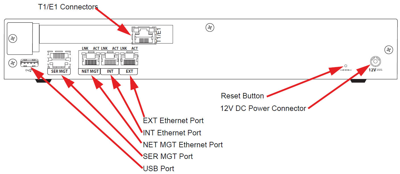
Power Connector
12V of DC power is supplied to the 12V DC power connector via an external AC power supply. (Options are available for providing a country-specific AC cable.)
Reset Button
A hard reset of the Acme Packet 1100 can be performed by pressing the reset button. This button is recessed and can only be pressed by inserting a thin wire (e.g., a paper clip) through the reset button channel. Pressing the reset button can result in the loss of software data or your configuration.
Pressing the reset button causes a hard reset by immediately rebooting the Acme Packet 1100. After the reset button is released, the Acme Packet 1100 begins its boot sequence and loads the configured software file.
T1/E1 Connector(s) (Optional)
The optional T1/E1 ports allow for connection to TDM connections. The T1/E1 port is an RJ48C port available on a PCIe card that mounts in the spare slot on the rear of the chassis.
EXT (s0p1) Ethernet Port
The EXT 10/100 Mbps Ethernet port allows for connection to a SIP trunk from a service provider. The INT and EXT Ethernet ports are media ports.
The EXT LNK LED and EXT ACT LED indicate the respective link and activity over the EXT Ethernet port on the rear of the chassis. See the section on Network Management Ports for further information on the meaning and use of these LEDs as they pertain to the EXT port.
INT (s0p0) Ethernet Port
The INT 10/100 Mbps Ethernet port allows for connection to an internal network (e.g., IPBX). The INT and EXT Ethernet ports are media ports.
The INT LNK LED and INT ACT LED indicate the respective link and activity over the INT Ethernet port on the rear of the chassis. See the section on Network Management Ports for further information on the meaning and use of these LEDs as they pertain to the INT port.
NET MGT (wancom0) Ethernet Port
The NET MGT 10/100 Mbps Ethernet port allows for configuring the Acme Packet 1100 and for providing high availability (HA) for the chassis. Two Acme Packet 1100s can connect from their respective NET MGT Ethernet port to a single Ethernet switch and be configured in an active/standby HA configuration.
The NET MGT LNK LED and NET MGT ACT LED indicate the respective link and activity over the NET MGT Ethernet port on the rear of the chassis. See the section on Network Management Ports for further information on the meaning and use of these LEDs as they pertain to the NET MGT Ethernet port.
USB Port
The USB port is reserved for software-enabled applications such as firmware and system upgrades and for remote access by customer service representatives. The USB port is for Acme Packet use only and is not to be used by the customer unless directed by a customer service representative.
SER MGT (COM2) System Console Port
The SER MGT port provides system console access to the Acme Packet 1100 via a console over an RS-232C serial connection. The SER MGT console port is useful for customers who want permanent console access to the Acme Packet 1100.
- Creating the initial connection to the Acme Packet 1100
- Accessing and using all functionality available via the ACLI
- Performing in-lab system maintenance
SER MGT System Console Port Pin-out
The Acme Packet 1100 SER MGT system console port is accessed through the RJ45 jack in the rear of the system. Because the Acme Packet 1100 does not employ any type of flow control on its RS-232 ports, only the RX, TX, and GND pins are used. The following table identifies the pin assignments and signal names/descriptions for the SER MGT console connector.
Table 2-1 Console Port Pin-Out
| Pin Number | Signal Name/Description |
|---|---|
| 3 | Receive Data (RX) |
| 2 | Ground (GND) |
| 6 | Transmit Data (TX) |
Ethernet LEDs
Each Ethernet jack has two integrated LEDs, one to indicate Link and one to indicate Activity, as shown in the illustration below. The LED pair is located directly above its associated port. These LEDs are explained in the following subsections.
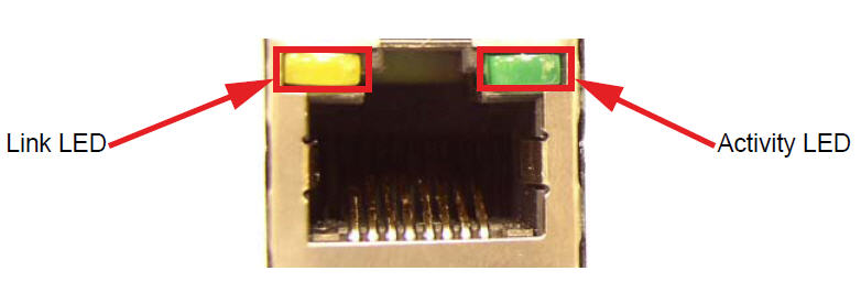
Link LED
The link LED glows orange when a link has been established between the link partner device and the SBC.
Activity LED
The activity LED glows green when an Ethernet connection has either transmit or receive packet activity.
Upon initial bootup, the Acme Packet 1100 Ethernet ports are not configured. You must first connect to the Acme Packet 1100 over a serial connection before you can configure the management Ethernet ports for use. Set up the management interfaces using the physical and network interface configuration elements. Refer to the System Configuration chapter of the Configuration Guide for details.
- Maintenance activities
- Application log retrieval
- Software upgrades
- System configuration
- Telnet, SSH, SNMP, FTP, and SFTP connections
- RADIUS CDR transmission
Oracle recommends that you use shielded CAT5e or CAT6 Ethernet cables with RJ45 plugs for connecting to the rear-panel Acme Packet 1100 Ethernet interfaces. These Ethernet interfaces have a distance limitation of 328 feet (100 m) as defined by the FAST Ethernet standard, IEEE 802.3.