3 SEPP Features
This section explains the SEPP features.
Note:
The performance and capacity of the SEPP system may vary based on the call model, Feature/Interface configuration, and underlying CNE and hardware environment.
3.1 Load Sharing among Multiple Remote SEPP Nodes
Until the current release, SEPP could only redirect traffic to the secondary remote SEPP when the primary SEPP was unavailable, allowing for the use of only one SEPP at a time.
With load sharing among multiple Remote SEPP nodes feature, SEPP can now efficiently distribute incoming traffic among multiple remote SEPPs. To enable this, the operator needs to configure a single virtual FQDN for the remote SEPPs. SEPP retrieves multiple Remote SEPP records from the DNS server and distributes the traffic according to the priority and weight associated with each record. Hence, SEPP can simultaneously route the incoming requests to multiple Remote SEPPs.
Feature OverviewThis feature enables SEPP to perform DNS SRV Query to discover Remote SEPPs. This enhances the capability of DNS SRV which already supports DNS Query capability. This feature eases the operation and maintenance for the customer when the failover nodes are configured in the DNS server for different SEPPs. Previously, users were configuring the FQDNs locally for each SEPP. This configuration also allows the operator to establish a backup/failover pair of a notify consumer or producer within DNS. In case of a notify or service request failure, SEPP can then choose this backup configuration for retry purposes.
The following is the format of SRV records defined at DNS server:
_Service._Proto.Name TTL Class SRV Priority Weight Port Target
_http._tcp.example.com 86400 IN SRV 1 10 80 blr.example.com
In this example, the virtual FQDN "example.com" returns the single FQDN record "blr.example.com" with priority 1 and weight 10.
Similarly, multiple records can be defined against the single virtual FQDN. Each FQDN returned can be resolved to multiple IP address in the DNS server.
Assumptions- SEPP FQDN and Virtual FQDN should be mapped to a valid IP address or multiple IP addresses. SEPP FQDN is used for the N32c handshake procedure.
- The load sharing feature is only used for the N32F traffic at N32-egress-gateway.
- Remote SEPP Set cannot have multiple peers with different Virtual FQDNs.
- Only a single Remote SEPP from the multiple Remote SEPPs with the same virtual FQDNs needs to be associated with Remote SEPP Set.
- SEPPs sharing the same Virtual FQDN should belong to the same set of PLMNs.
- Deployment of Alternate Route Service is mandatory for using load sharing feature at both the Egress Gateways.
- Correct DNS configuration is up to the discretion of the user. It is possible that the SEPP may or may not have handshake established within its database.
- Selective routing to Remote SEPPs based on server header is currently not supported.
Detailed Description
The following diagram represents the load sharing among multiple Remote SEPP nodes feature:
Figure 3-1 Architecture
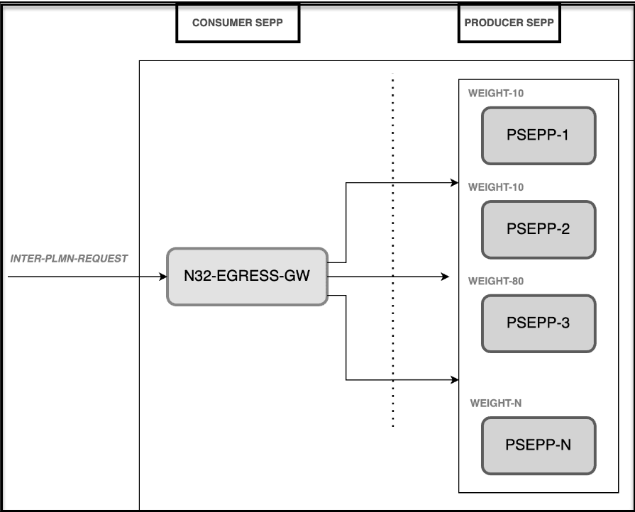
Oracle SEPP supports load sharing of incoming 5G traffic to multiple Remote SEPPs with the help of load sharing feature at Egress Gateway. Single virtual host is configured for all the Remote SEPPs that share the same PLMN ID list. Virtual Host is mapped to the Remote SEPPs' FQDN records, and each having its own priority and weight values. Egress Gateway retrieves the records from the DNS server and arranges them in the order of priority and weight. If the priorities of all the fetched records against the virtual host are same, then the requests are load-shared among the Remote SEPPs on the basis of weight value assigned to each record. If any of the peers are unavailable, then the load gets redistributed to the remaining peers based on their priority and weight factor. This redistribution depends on whether the error code received from the peer is correctly configured in the database.
Managing Load Sharing among Multiple Remote SEPP Nodes Feature
This section describes the procedure to enable the feature.
PrerequisitesThe following are the prerequisites to enable and configure the feature:
Configure the
following Helm parameters in the
ocsepp_custom_values_<version>.yaml file.
dnsSrvEnabled: true
alternateRouteServiceEnable: true
dnsSrvFqdnSetting.enabled: false
dnsSrvFqdnSetting.pattern: "_{scheme}._tcp.{fqdn}."
Note:
Scheme must be always be "http".alternateRouteServiceEnable: trueNote:
Additionally, for Roaming Hub deployment, enable theglobal.appinfoServiceEnable: true.
For more information, see Oracle Communications Cloud Native Core, Security Edge Protection Proxy Installation, Upgrade, and Fault Recovery Guide.
EnablingYou can enable the load sharing among multiple Remote SEPP nodes feature using the CNC Console or REST API by adding the Virtual Host parameter at the Remote SEPP Profile.
Note:
If the Virtual Host parameter is left blank, then the feature is disabled.Remote SEPP (with virtual host configuration) must be associated with the Remote SEPP Set.
For more details about CNC Console Configurations, see Configuring SEPP using CNC Console section in the Oracle Communications Cloud Native Core, Security Edge Protection Proxy User Guide.
For more information about API path, see Oracle Communications Cloud Native Core, Security Edge Protection Proxy REST Specification Guide.
Configure
You can configure the feature using REST API and CNC Console.
- Configure using REST API: Perform the feature configurations as described in the Remote SEPP REST API in Oracle Communications Cloud Native Core, Security Edge Protection Proxy REST Specification Guide.
- Configure using CNC Console: Perform the feature configurations as described in the Remote SEPP in the Configuring SEPP using CNC Console section.
Observe
Following are the feature specific metrics:
- oc_egressgateway_sbiRouting_http_responses_total
For more information about metrics and KPIs, see SEPP Metrics and SEPP KPIs sections.
Maintain
If you encounter alerts at system or application levels, see SEPP Alerts section for resolution steps.
In case the alert still persists, perform the following:
- Collect the logs and Troubleshooting Scenarios: For more information on how to collect logs and troubleshooting information, see Oracle Communications Cloud Native Core, Security Edge Protection Proxy Troubleshooting Guide.
- Raise a service request: See My Oracle Support for more information on how to raise a service request.
3.2 Separate Port Configurations for N32c and N32f on the Egress Routes
SEPP was previously configured to support a single port or connection for both the control plane interface (n23c) and the forwarding interface (n32f). The Egress Gateway was set up to establish the connection of n32c and n32f on the same port, making it challenging to segregate the traffic. This also prevented SEPP from initiating connections to Remote SEPPs that required a different address for the n32c and n32f interfaces.
To improve traffic segregation, the Egress Gateway is enhanced by configuring different ports for the n32c and n32f connections on both the Remote SEPP Set and its local configurations.
Design and Architecture
The following diagram represents the separate port configurations for n32c and n32f on the Egress routes feature:
Figure 3-2 Separate Port Configurations Design Diagram

As represented in the diagram, the n32 Egress Gateway in the Oracle SEPP is configured to use different IP addresses or ports for connecting on the n32c and n32f interfaces on the same Remote SEPP. The n32f configuration in the Remote SEPP profile initiates separate connections toward the forwarding pane and control pane of the Remote SEPP. The forwarding plane can have the distinct FQDN and port.
If the n32f configuration is not present, then it is assumed that the control plane and forwarding plane have the same FQDN, IP address, and port combination.
Managing Separate Port Configurations for N32c and N32f on the Egress Routes
This section describes the procedure to enable the feature.
You can enable separate port configurations for n32c and n32f on the egress routes feature using the CNC Console or REST API by adding the n32 configuration parameters at the Remote SEPP profile. The parameters are N32F FQDN, N32F IP Address, and N32F Port.
Note:
If the N32F FQDN, N32F IP Address, and N32F Port parameters are left blank, then the feature is disabled.For more details about CNC Console Configurations, see Configuring SEPP using CNC Console section in the Oracle Communications Cloud Native Core, Security Edge Protection Proxy User Guide.
For more information about REST API path, see Oracle Communications Cloud Native Core, Security Edge Protection Proxy REST Specification Guide.
Configure
You can configure the feature using REST API and CNC Console.
- Configure using REST API: Perform the feature configurations as described in the Remote SEPP REST API in Oracle Communications Cloud Native Core, Security Edge Protection Proxy REST Specification Guide.
- Configure using CNC Console: Perform the feature configurations as described in the Remote SEPP in the Configuring SEPP using CNC Console section.
Observe
For more information about metrics and KPIs, see SEPP Metrics and SEPP KPIs sections.
Maintain
If you encounter alerts at system or application levels, see SEPP Alerts section for resolution steps.
In case the alert still persists, perform the following:
- Collect the logs and troubleshooting scenarios: For more information on how to collect logs and troubleshooting information, see Oracle Communications Cloud Native Core, Security Edge Protection Proxy Troubleshooting Guide.
- Raise a service request: See My Oracle Support for more information on how to raise a service request.
3.3 Support for cnDBTier APIs in CNC Console
With the implementation of this feature, cnDBTier APIs are integrated into the CNC Console. SEPP users can view specific cnDBTier APIs such as checking the cnDBTier version, status of cnDBTier clusters, and georeplication status on the CNC Console.
- Backup List: This API displays the details of stored backups, such as the ID and size of the backup.
- cnDBTier version: This API displays the cnDBTier version.
- Database Statistics Report: This API displays the number of available database.
- Geo Replication Status:
- Real Time Overall Replication Status: This API displays the overall replication status in multisite deployments. For example, in a four-site deployment, it provides the replication status between the following sites: site1-site2, site1-site3, site1-site4, site2-site3, site2-site4, and site2-site1. This is applicable for all other sites.
- Site Specific Real Time Replication Status: This API displays the site-specific replication status.
- HeartBeat Status: This API displays the connectivity status between the local site and the remote site name to which SEPP is connected.
- Local Cluster Status: This API displays the status of the local cluster.
- On-Demand Backup: This API displays the status of initiated on-demand backups.
Note:
This feature works when cnDBTier is configured as an instance during the CNC Console deployment. For more information about integrating cnDBTier APIs in CNC Console, see Oracle Communications Cloud Native Core, cnDBTier User Guide.You can view the cnDBTier GUI in the CNC Console. For more information, see cnDBTier in the CNC Console.
Maintain
If you encounter alerts at system or application levels, see SEPP Alerts section for resolution steps.
In case the alert still persists, perform the following:
- Collect the logs and Troubleshooting Scenarios: For more information on how to collect logs and troubleshooting information, see Oracle Communications Cloud Native Core, Security Edge Protection Proxy Troubleshooting Guide.
- Raise a service request: See My Oracle Support for more information on how to raise a service request.
3.4 5G SBI Message Mediation Support
In the earlier releases, SEPP supports Mediation as an independent service to modify 5G Service Based Interface (SBI) message content, which includes HTTP2 header values and JSON message body, based on the user-defined mediation rule sets.
The message mediation feature at SEPP allows MNOs to resolve the inter-op issues between PLMNs by manipulating the inter PLMN messages. SEPP uses the mediation service to support message mediation. The MNO relies on mediation service capabilities to provide the mediation rules.
SEPP is enhanced to include mediation as a microservice, that applies user-configured message mediation rules to ingress 5G SBI messages to perform message mediation transformation. Mediation is a common microservice reused across Oracle NFs. The mediation feature allows user-defined business rules to filter or manipulate headers, Query Parameters and Body Parameters in SBI request and response messages. Mediation is invoked by CN32f and PN32f microservices when the request and response matches the configured trigger rules. Trigger Rule Configuration is managed by SEPP. Mediation Rule Configuration used by Mediation microservice is managed by Mediation microservice.
Mediation Representation with SEPP
Figure 3-3 Mediation Representation with SEPP

Managing Mediation
-
To deploy this service, set the
mediationServiceparameter to true in the global parameters section of thecustom valuefile.Example:
For more information about this parameter, see Oracle Communications Cloud Native Core, Security Edge Protection Proxy Installation, Upgrade, and Fault Recovery Guide.nf-mediation: # mediation Global configuration global: mediationService: true
You can enable the feature using REST API and the CNC Console.
To enable the feature, set the Enable Mediation
parameter to true in the Options screen under the
Mediation section of the CNC Console GUI.
Following Configuration are required at SEPP to apply 5G SBI Message Mediation Support feature:
- Trigger Rule Configuration
- Mediation Rule Configuration
Trigger Rule Configuration
Mediation Trigger Rule List for SEPPSEPP allows user to configure Trigger Rule List as a filtering criteria, based on which the mediation functionality is invoked. 5G SBI Message Mediation Support functionality can be applied on a Local SEPP and on a Remote SEPP Set, hence Trigger Rules can be configured for Local and Remote SEPP Set. That is, the user can apply mediation rule on a request going out or a response coming in for this particular local SEPP or the user can apply mediation rule on a request going out or a response coming in for this particular Remote SEPP Set. Every Trigger Rule List must contain a unique name.
SEPP also extends its functionality for the user to apply 5G SBI Message Mediation Support functionality on every request and response that is received on SEPP by selecting Match All option on the console.
Filtering Criteria for Message Mediation functionality to be invokedSEPP allows user to configure Multiple Trigger Rules in Trigger Rule List which then includes Trigger Points, Resource URI, HTTP Method, and Group ID. In this Trigger Points, Resource URI, and HTTP Method are used as a filtering Condition by SEPP to select if a particular request needs Message Mediation functionality invocation or not. Here User is allowed to configure unique combination of Trigger points, Resource URI, and HTTP Method for every Trigger Rule in a Trigger Rule list.
Mediation Trigger Points for SEPPSEPP supports the following mediation trigger points to invoke mediation service:
- Ingress inter-PLMN and core network messages
- Egress inter-PLMN messages
Hence, Trigger Point can be any of the following:
- N32 EGRESS REQUEST
- N32 INGRESS RESPONSE
- N32 INGRESS REQUEST
- N32 EGRESS RESPONSE
The Trigger Points are available only in the context of the N32 interface/traffic.
Resource URIThere are certain SBI messages which traverse through networks. On the basis of the default list of all the Inter PLMN SBI Messages, SEPP Message Mediation feature allows the user to configure only the allowed Inter PLMN SBI Messages. User is allowed to add any new Resource URI as per their requirement. To add any new Resource URI and HTTP Method, user can add the same in SEPP Service APIs section in CNC Console. Once an API is added, the same can be reflected under Resource URI of Trigger Rule.
HTTP MethodSEPP allows the user to configure the following predefined HTTP Methods for Message Mediation feature:
- POST
- PUT
- GET
- PATCH
- DELETE
- OPTIONS
SEPP uses Group ID for which mediation configuration is to be done. This is passed to the Mediation Service for grouping similar rules. It is of type string.
Agenda Group Naming
User can combine mediation rules by using Agenda Group in the mediation rule definition.
Agenda group is the combination of Group id and Trigger Point (configured in Trigger Rule in Configuring SEPP using CNC Console).
Agenda group name in mediation rules should be <Group Id>-<triggerpoint> as shown in the following example:
agenda-group "AUSF-N32_Ingress_Request"
function String modifySupiOrSuci(String str) {
        String supiOrSuci = str.substring(0,15)+"0000"+str.substring(16);
        return supiOrSuci;
}


rule "Match SUPI_SUCI Modify"
    agenda-group "AUSF-N32_Ingress_Request"
when
    req : Request(body.has("$.supiOrSuci"))
then
    req.body.put("$","supiOrSuci",modifySupiOrSuci(req.body.get("$.supiOrSuci").toString()))
end
User can refer the Mediation Service Rule Book in the Appendix to configure the Mediation Rules.
Examples of Use Cases supported by SEPP
- Incoming SUCI (Subscription Concealed Identifier) format
modification and then using modified SUPI (Subscription Permanent Identifier)
for selection:
- Example: "supiOrSuci": "suci-0-310-260-0-0-0-173416067 is first modified to "supiOrSuci": "suci-0-310-260-0000-0-0-173416067
- Example: "imei-9844312345123456" is modified to "imei-984431234512345"
- Validating SUCI for format and sending Custom error code
- Example: "supiOrSuci": "suci-0-310-260-0-0-0-173416067 is checked and instead of 404 Not found, error sent to AMF is modified to 403 “invalid SUCI format”.
- When ingress request doesn't come in a supported scheme
- Example: Visited Network works only with http, but home network requires https.
Only following combination are allowed to be configured in 5G SBI Message Mediation Support feature for local and Remote SEPP with Match All Configuration.
Table 3-1 Match All Configurations
| Match ALL | Local/ Remote | Description |
|---|---|---|
| True | Local | This combination is used for applying mediation rules for all the inter PLMN SBI requests or responses for all the peer SEPPs. |
| True | Remote | This combination is used for applying mediation rules for all the inter PLMN SBI requests or responses for a particular peer SEPP for which trigger rule list is configured. |
| False | Local | This combination is used for applying mediation rules on selected (using Trigger points, Resource URI, and HTTP Method) inter PLMN SBI requests or responses for all the peer SEPPs. |
| False | Remote | This combination is used for applying mediation rules on selected (using Trigger points, Resource URI, and HTTP Method) inter PLMN SBI requests or responses for a particular peer SEPP for which trigger rule list is configured. |
Once a Trigger Rule list is created with Trigger Rules, user is allowed to associate a Trigger Rule List with the Configured Remote SEPP Sets.
User can select the Remote SEPP Set screen on CNC Console and can select Trigger Rule List under Trigger Rule List Name field.
Note:
The user can associate a Trigger Rule list created exclusively for the Remote SEPP Set but is not permitted to associate a Trigger Rule list created for a Local SEPP with the Remote SEPP Set.Error action (Reject or Continue) with status code and title is configurable and used for error response. When an error response is received from Mediation microservice the configured error action by user is applied on message.
User is allowed to configure Error action with status code and title to be used with Errors. When an error response is received from the Mediation microservice, the configured error action is applied on message.
Error Action can be:
- Continue: SEPP persists in processing the message, even if an error response is received from the Mediation microservice.
- Reject: SEPP will decline the message and provide a user-configured status code and title.
Mediation Rule Configuration
You can configure the Mediation rules either using config map, or using REST API and CNC Console.
- Download the configMap into a file using the following
command:
kubectl get configmap ocsepp-release-nf-mediation-config-active -n sepp-med3 -oyaml > rule_configmap.txt - At the end of the file rule_configmap.txt , append the
below data block along with needed rules:
Example of updated file:
data: rule.drl: | package com.oracle.cgbu.ocmediation.nfmediation; import com.oracle.cgbu.ocmediation.nfruleengine.NFDroolsRuleEngine; import com.oracle.cgbu.ocmediation.factdetails.Request; import com.oracle.cgbu.ocmediation.factdetails.Response; import java.util.Map; import java.util.HashMap; dialect "mvel" //rulesapiVersion: v1 kind: ConfigMap metadata: annotations: meta.helm.sh/release-name: ocsepp-release meta.helm.sh/release-namespace: sepp-med3 creationTimestamp: "2022-08-21T09:37:03Z" labels: app.kubernetes.io/managed-by: Helm name: ocsepp-release-nf-mediation-config-active namespace: sepp-med3 resourceVersion: "15059111" uid: 10baf42f-3582-49a7-8cd1-7228357c9a54 data: rule.drl: | package com.oracle.cgbu.ocmediation.nfmediation; import com.oracle.cgbu.ocmediation.nfruleengine.NFDroolsRuleEngine; import com.oracle.cgbu.ocmediation.factdetails.Request; import com.oracle.cgbu.ocmediation.factdetails.Response; import java.util.Map; import java.util.HashMap; dialect "mvel" rule "Rule_show_add_header" when req : Request(headers.has("3gpp-Sbi-Message-Priority") == true) then req.headers.add("3gpp-Sbi-Message-Priority","10") req.headers.del("x-test-req-header1") end rule "Rule_Request_body_add_delete" when req : Request(headers.has("x-forwarded-NF","NRF")) then req.body.put("$","nfId","ccc5ccbb-5bb9-465f-9ace-0faf08cb4223") req.body.del("$.supiOrSuci") end - Run the following command to update the configmap with the
updated
rules:
kubectl replace ocsepp-release-nf-mediation-config-active -n sepp-med3 -f rule_configmap.txtNote:
- If rules changed on nf active mediation then use "$releaseName-nf-mediation-config-active" as the name of the configmap.
- It is recommended to maintain the back up of the rules as it can lead to rule loss if the config map deleted.
Mediation Rules using CNC Console and Rest APIs
The above process of creating mediation rules in mediation-nf using a configmap with Kubernetes has several limitations, such as configuring the code to create and update the mediation rules using a configmap, whose size is limited to 1 MB.
With this feature enhancement in release 23.4.0, mediation rules are being stored in the database, these rules can be retrieved, modified, deleted, new rules can be added and applied to mediation microservice using the CNC Console or REST API, leveraging improved database storage capacitiy.
The following are the user configurable Mediation Rules Parameters:
- Rule Name: Unique mediation rule name for identification.
- Status: APPLIED or DRAFT. New mediation rule(s) are always created and stored with DRAFT status into the database. Once the rules are saved again using Apply state, they will be applied to the mediation microservice and the status will be APPLIED.
- State: Possible rule state values are Save, Compile, Apply, Clone, and Draft. New rule(s) are always created using Save state. Once created, user can select the other states.
- Mediation Mode: Possible values of mode are MEIDATION_ACTIVE and
MEIDATION_TEST. The user is required to configure the mediation rules using
MEDIATION_ACTIVE mediation mode. MEDIATION_TEST mode is only for internal
purpose.
- MEIDATION_ACTIVE: It is applicable only to mediation microservice active mode.
- MEDIATION_TEST: It is applicable only to mediation microservice test mode.
- Code: Mediation rule code. The user needs to perpend the following data block along with the needed rules. User will be restricted to apply a rule that is having any compilation or syntax error in it. Any special character in code results in a rule compilation error.
    package com.oracle.cgbu.ocmediation.nfmediation;

    import com.oracle.cgbu.ocmediation.nfruleengine.NFDroolsRuleEngine;
    import com.oracle.cgbu.ocmediation.factdetails.Request;
    import com.oracle.cgbu.ocmediation.factdetails.Response;
    import java.util.Map;
    import java.util.HashMap;

    dialect "mvel"

//rules- Format: Rule format. Only DRL is supported currently.
- New Rule Name: New mediation rule name is to be given only when an existing rule is cloned using Clone state.
The following diagram represents the rule state and status flow:
Figure 3-4 Rule Status Flow

- Save: It saves an existing rule into the database.
- Compile: It only compiles the rule and saves it again into the data base.
- Clone: It works same as "save as". That is, saves an existing rule with a new given name into the database.
- Apply: It compiles the rule, saves it again in APPLIED status into the database, and applies the rule to mediation microservice.
- Draft: Its not supported as rule status is already DRAFT.
- Save: It applies the rule with changed mediation mode to the mediation microservice. While using this state, user can only change the rule mode, that is, MEDIATION_ACTIVE to MEDIATION_TEST and vice versa. Modification in rules code is not allowed.
- Compile: Its not allowed as rule had been already compiled while applying it earlier.
- Clone: It works same as "save as", that is, saves an existing rule with a new given name into the database in DRAFT status.
- Apply: Its not allowed as rule is already in APPLIED status.
- Draft: It removes the APPLIED rule from mediation microservice, and saves again the rule in database in DRAFT status. While using this state, any change in the rule code is not allowed. Any code changes can be done once the rule status has been successfully changed to DRAFT status.
Note:
- In SEPP release 23.4.0, the user is recommented to configure the mediation rules using CNC Console or REST APIs. However, configuring the mediation rules using config map is still supported and might be removed in the future releases.
- The
mediationConfig.ruleApi.enabledhelm flag is used to enable or disable the CNC Console or REST API based rules configurations feature implementation. If the flag value is true, mediation microservice uses the rules from the database configured using CNC Console or REST APIs. If the flag value is false, mediation microservice uses the rules configured in the config map. The default value of the flag is true. - If an upgrade is performed from earlier SEPP releases to 23.4.0 release, the earlier releases' mediation rules that are available in the config map will be copied into the database table in APPLIED state and that can be viewed, modified, or deleted using CNC console or REST APIs in 23.4.0 release.
- After an upgrade, if a rollback is performed from SEPP release 23.4.0 to earlier releases, the config map will have the same rules that were present before the upgrade.
For more information on creating mediation rules using CNC Console or REST API, see the Mediation Rules Configuration or Cloud Native Core, Security Edge Protection Proxy REST Specification Guide.
Custom Headers
Table 3-2 Custom Headers
| CustomHeader | Original Message Header |
|---|---|
| x-original-method | ":method" |
| x-original-scheme | ":scheme" |
| x-original-authority | ":authority" |
| x-original-path | URI of original message |
| x-original-status | ":status" |
| x-message-type | value can be "request" or "response" Default value :"request" |
Mediation Header
In cn32f and pn32f section, user can set mediation Request timeout time. N32f service wait for mediation svc response for mediationRequestTimeout time before sending the error message, if mediation service is unreachable.
In mediation rules,user can reject any incoming request. To reject request, user has to add some headers in mediation response which helps n32f services in making the decision. Two header Parameters are user configurable for this purpose.
mediationRequestRejectStatusCodeHeaderName: The name of the header added in response to depict that n32f service has to reject this request and the value of this header indicates the error code to be returned.mediationRequestRejectReasonHeaderName:The name of the header added in response to depict that n32f service has to reject this request and the value of this header indicates the error reason to be returned.Example:
mediation:
   mediationRequestTimeout: 900
   header:
     mediationRequestRejectStatusCodeHeaderName: "ocsepp-reject-status"
     mediationRequestRejectReasonHeaderName: "ocsepp-reject-reason"
Observe
For more information the Metrics and KPIs, see SEPP Metrics and SEPP KPIs sections.
Maintain
If you encounter alerts at system or application levels, see SEPP Alerts section for resolution steps.
In case the alert still persists, perform the following:
- Collect the logs: For more information on how to collect logs, see Oracle Communications Cloud Native Core Security Edge Protection Proxy Troubleshooting Guide.
- Raise a service request: See My Oracle Support for more information on how to raise a service request.
3.5 Topology Hiding
Oracle Communications Security Edge Protection Proxy (SEPP) is a proxy network function (NF) which is used for secured communication between inter-Public Land Mobile Network (PLMN) messages. SEPP provides message filtering and policing on inter-PLMN control plane interfaces and topology hiding.
Topology hiding is a security feature in 5G that secures the address of the network elements and can prevent the attacks intended for unauthorized access to network element or interruption of the network service. The purpose of the feature is to enable topology hiding of information from the home or visited PLMN to the visited or Home PLMN. Topology Hiding conceals identity information from all messages leaving a PLMN.
Design and Architecture
The following diagram represents the detailed architecture of the Topology Hiding feature.
Figure 3-5 Topology Hiding Architecture
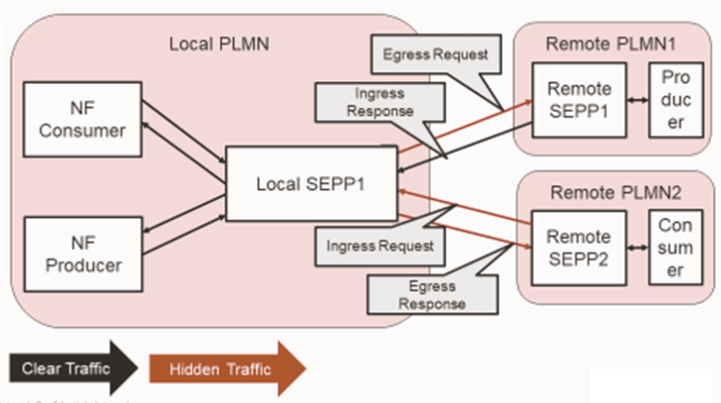
If the Topology Hiding feature is enabled, based on the header and body table configuration, either the message will be masked with the hidden value ( if the operation is TH -Topology Hiding) or the message will be represented by the actual value (if the operation is TUH -Topology Recovery), where the hidden value is mapped to the actual value.
Hidden traffic: The traffic is marked as hidden traffic, if the message (header and body) is masked with the hidden value (operation is TH) or the message is represented by the actual value (operation is TUH).
Clear traffic: The traffic is marked as clear traffic, if the request or response does not have any of the header and body configurations mentioned in the header or body configuration table.
Note:
Topology Hiding is applicable only to N32f and not to N32c.Note:
Only FQDN, NF_INSTANCE_ID, and NF_SERVICE_INSTANCE_ID can be updated or modified for hiding or recovery in the message header or body identifier.Header and Body Table Configuration
- Egress Request
- Egress Response
- Ingress Request
- Ingress Response
Ingress response has a clear traffic, as any messages for TH or TUH are not defined in the ingress response.
Note:
In Topology Hiding feature, each request and response are considered as separate operations. Neither request header/identifiers nor response header/identifiers can be related to each other in any of the operations. Both request and response should be treated as separate isolated transactions.
Actual to Pseudo Mapping
User can perform actual to pseudo mapping through CNC Console GUI. While configuring the pseud values, user has to add the specific unique prefix and suffix to make pseudo names globally unique. This is necessary to make topology hiding functionality efficient.
Figure 3-6 Actual to Pseudo Mapping
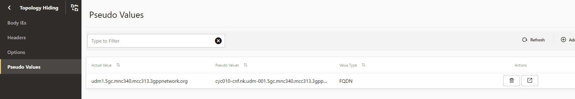
The actual values and pseudo values are mapped and stored in the actual_values and pseudo_values tables.
Table 3-3 Header configuration
| Header Name | Regular Expression | Trigger Point | Operation |
|---|---|---|---|
| via | (?<=SCP-).* | Request Egress | Topology Hiding |
| via | (?<=SCP-).* | Response Egress | Topology Hiding |
| location | (?<=http://|https://)[^:/?]+ | Response Egress | Topology Hiding |
| server | (?<=SCP-|UDM-)([^ ]*) | Response Egress | Topology Hiding |
| 3gpp-sbi-target-apiroot | (?<=http://|https://)[^:/?]+ | Request Ingress | Topology Recovery |
| 3gpp-sbi-routing-binding | (?<=nfinst=|nfservinst=|backupamfinst=|backupnf=)([^;]+) | Request Ingress | Topology Recovery |
| 3gpp-sbi-binding | (?<=nfinst=|nfservinst=|backupamfinst=|backupnf=)([^;]+) | Request Egress | Topology Hiding |
| 3gpp-sbi-binding | (?<=nfinst=|nfservinst=|backupamfinst=|backupnf=)([^;]+) | Response Egress | Topology Hiding |
TH: Topology Hiding
TUH: Topology Recovery
Note:
The user must configure the actual to pseudo mappings for the all the headers mentioned in the above table. The above mentioned are the default header configuration that is added by default and user must configure the actual to pseudo mappings for the all the headers mentioned in the above table.Messages passing through the system check all the above configured conditions. The direction and the message type for the header configured in the table are validated and perform the TH or TUH based on the operation configured in the table.
The Helm parameter, TOPOLOGY_HIDING_MAX_PSEUDO_VALUE is by default set to 7. So user can add minimum one and maximum 7 pseudo values in the system. For any actual value, user can configure 7 pseudo values. If this actual value has to be hidden, then a random value is being picked up out of these 7 pseudo values and will be used for hiding.
TH and TUH operation is run based on the actual/pseudo mapping that user has configured in the system. By default, for any one actual value we can map at most 7 pseudo values. If the user perform TH and TUH, then value that is eligible for TH/TUH will be looked up in the mapping and accordingly TH/TUH operation is being performed.
- FQDN
- NF_INSTANCE_ID
- NF_SERVICE_INSTANCE_ID. The user cannot add same pseudo value for the different actual values and duplicate pseudo values are not allowed.
When the incoming message or outgoing message has the header that is eligible for performing TH/TUH, the actual or pseudo value of that specific header is extracted and compared it with the actual to pseudo mapping. Once the mapping operation to be performed is identified, if it is TH, the actual value is masked from the pseudo mapping and if it is TUH, recover the pseudo value with the actual value received from mapping.
Query Parameters
With the Resource URI request, there can be a possibility where request URL contains the key value pair. These values can be one of FQDN, NF_INSTANCE_ID, or NF_SERVICE_INSTANCE_ID types and should be eligible for TH/TUH.
User can add the path header in the header table and specify the relevant configuration such as headerName, DIRECTION, Regular Expression, MessageType, operations. Then the keys coming in the path will be treated as headers.
Note:
If the key is added as header in the header table, then every request will be processed for these keys as header (if available in request). Configuration done at header table configuration is applicable for all request and response.Note:
User must do the actual to pseudo mapping, else hiding and recovery operations fails.
Example:
curl -v --http2-prior-knowledge 'http://127.0.0.1:9090/nnrf-disc/v1/nf-instances?service-names=nausf-auth&target-nf-type=AUSF&requester-nf-type=NRF&target-plmn-list=%5B%7B%22mcc%22%3A%22310%22%2C%20%22mnc%22%3A%22300%22%7D%5D&requester-plmn-list=%5B%7B%22mcc%22%3A%22310%22%2C%22mnc%22%3A%22310%22%7D%2C%7B%22mcc%22%3A%22311%22%2C%22mnc%22%3A%22490%22%7D%5D&routing-indicator=0000&requester-nf-instance-fqdn=https://pseudo.mnc330.mcc310.BE4NRF06.rs.nokia.com:9090' -H 'Content-Type: application/json' -H 'x-forwarded-host:ausf.default.mnc444.mcc444.3pnetwork.org' -H 'x-forwarded-port:8080' -H '3gpp-sbi-target-apiroot: http://ausf.default.mnc444.mcc444.3pnetwork.org'In the above request if the user wants to hide or recover the requester -nf-instance-fqdn, then this parameter can be added as a header in the header table configuration and based on that hiding or recovery performed.
For the above example, the Header table will be as follows:
Table 3-4 Example of Header Table
| Header Name | Regular Expression | Trigger Point | Operation |
|---|---|---|---|
| requester-nf-instance-fqdn | ((?<=http://|https://)[^:/?]+) | Request Egress | Topology Hiding |
Body Configuration
When the request or response message is passing through the system then the request body or response body is processed and its identifiers are hidden or unhidden based on the rules defined in the topology body table.
Every message passing through the system is having a unique apiUrl. Based on that rules for TH/TUH are defined. For every apiUrl, there are a list of identifiers that can be part of request or response based on that user can define the identifiers eligible for TH/TUH. User can configure like what operation needs to be performed when that body is processed.
Table 3-5 Example Body Configuration
| Method | API Response | Identifier | Regular Expression | Trigger Point | Operation |
|---|---|---|---|---|---|
| POST | /nnrf-nfm/v1/subscriptions | reqNfInstanceId | ^[0-9A-Fa-f]{8}-[0-9A-Fa-f]{4}-4[0-9A-Fa-f]{3}-[0-9A-Fa-f]{4}-[0-9A-Fa-f]{12}$ | N32_Egress_Request | Topology Hiding |
| POST | /nnrf-nfm/v1/subscriptions | nfStatusNotificationUri | (?<=http://|https://)[^:/?]+ | N32_Egress_Request | Topology Hiding |
| POST | /nnrf-nfm/v1/subscriptions | reqNfFqdn | ^(?!://)(?=.{1,255}$)((.{1,63}.){1,127}(?![0-9]*$)[a-z0-9-]?) | N32_Egress_Request | Topology Hiding |
| POST | /nnrf-nfm/v1/subscriptions | reqNfInstanceId | ^[0-9A-Fa-f]{8}-[0-9A-Fa-f]{4}-4[0-9A-Fa-f]{3}-[0-9A-Fa-f]{4}-[0-9A-Fa-f]{12}$ | N32_Ingress_Response | Topology Recovery |
| POST | /nnrf-nfm/v1/subscriptions | nfStatusNotificationUri | (?<=http://|https://)[^:/?]+ | N32_Ingress_Response | Topology Recovery |
| POST | /nnrf-nfm/v1/subscriptions | reqNfFqdn | ^(?!://)(?=.{1,255}$)((.{1,63}.){1,127}(?![0-9]*$)[a-z0-9-]?) | N32_Ingress_Response | Topology Recovery |
| POST | /nnrf-nfm/v1/subscriptions | hnrfUri | (?<=http://|https://)[^:/?]+ | N32_Ingress_Request | Topology Recovery |
| POST | /nnrf-nfm/v1/subscriptions | hnrfUri | (?<=http://|https://)[^:/?]+ | N32_Egress_Response | Topology Hiding |
If the same apiUrl having more than one identifiers then the separate rows of each identifiers must be in the database. One row always corresponds to single identifier configuration. If in case user enters the wrong or inappropriate configuration for any identifier then that particular configuration needs to be deleted and reenter back into the system
Note:
If the user wants to add the apiUrl and that is not present in the default table, exception or error occurs. Ensure to add the default configuration before configuring topology body.Note:
The actual to pseudo mapping should be done as mentioned in the above mentioned table. All the configuration related to actual pseudo mapping should apply in the same way.Path Parameters
Resource URIs or messages , where path is having some variable identifier that keeps on changing for the different request. Such APIs are mapped in the default table with syntax of the path variable and same syntax to be used in the topology body configuration if identifiers for that API needs to be part of TH/TUH.
Example:Consider the message request body going out from the system from CN32F (Ingress response) and having the apiUrl as /nnrf-disc/v1/nf-instances and containing eventNotifyUri identifier as http://udm1.5gc.mnc340.mcc313.3gppnetwork.org:8080/eventNotify and api method is of type POST. In this case, topology body table has the identifier eventNotifyUri configured for INGRESS RESPONSE as operation TH. This table checks the apiUrl which is actually called exists as a configuration in the table. Also, this method should be POST, so extract the eventNotifyUri from this message and consider this for TH.
Then look up the actual to pseudo mappings and try to find actual value as udm1.5gc.mnc340.mcc313.3gppnetwork.org and retrieve all the possible pseudo values associated with it. Once seven pseudo values against this actual value are identified, the system randomly select any one value and mask eventNotifyUri with pseudo value like eventNotifyUri: http://pseudo.default.mnc444.mcc444.3pnetwork.org:8080/eventNotify.
Example for Hiding the message
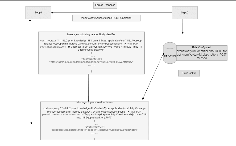
In the example via header is configured as hidden in the header table configuration and also eventNotifyUri as Body identifier for resource URI /namf-evts/v1/subscriptions in topology body configuration for the POST response. For the Egress Request message, via header is passed as actual value and eventNotifyUri as body identifier is passed as actual value. Since we have configured that TH operation should be performed therefore as per the actual/pseudo mapping mapped, TH should happen and actual values should convert into pseudo value. In the below example, it explains how we look up the database and convert the actual to pseudo value.
Example of Recovery
Consider the message request body going out from the system from CN32F (Egress Request) and having the apiUrl as /nnrf-disc/v1/nf-instances and containing eventNotifyUri identifier as http://pseudo.default.mnc444.mcc444.3pnetwork.org:8080/eventNotify and api method is of type POST. In this case, topology body table has the identifier eventNotifyUri configured for EGRESS REQUEST as operation TUH further this table checks that apiUrl which is actually called exists as a configuration in the table. Also, this method should be POST, so extract the eventNotifyUri from this message and consider this for TUH.
Look up the actual to pseudo mappings and find pseudo value as pseudo.default.mnc444.mcc444.3pnetwork.org and retrieve the actual value associated with it. System replaces the pseudo value with actual value udm1.5gc.mnc340.mcc313.3gppnetwork.org
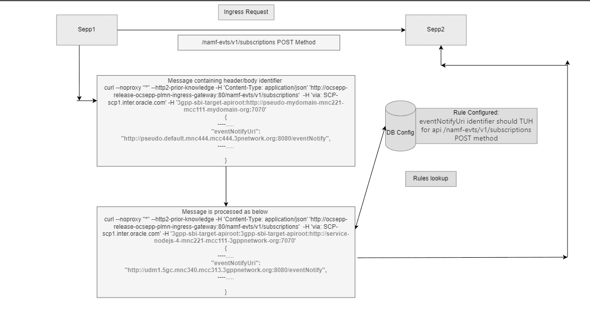
In the example, 3gpp-sbi-target-apiroot header is configured as recovered in the header table configuration and also eventNotifyUri as Body identifier for resource URI /namf-evts/v1/subscriptions in topology body configuration for the POST request. For the Ingress Request message, 3gpp-sbi-target-apiroot header is passed as pseudo value and eventNotifyUri as body identifier is passed as pseudo value. Since we have configured that TUH operation should be performed therefore as per the actual/pseudo mapping mapped, TUH should happen and psuedo values should convert into actual value. In the below example, it explains how we look up the database and convert the pseudo to actual value.
Default Configuration
The following is the default table that have all the resource URIs supported by the SEPP.
Table 3-6 Default Configuration
| id | resourceURI | method | regex |
|---|---|---|---|
| 1 | /nudm-sdm/v2/{supi} | GET | ^/nudm-sdm/v2/(imsi-[0-9]{5,15}|nai-.+|gci-.+|gli-.+|.+)/?$ |
| 2 | /nausf-auth/v1/ue-authentications/{authCtxId}/5g-aka-confirmation | PUT | ^/nausf-auth/v1/ue-authentications/([0-9a-zA-Z-]+|.+)/5g-aka-confirmation/?$ |
| 3 | /nudm-sdm/v2/{ueId}/sdm-subscriptions | POST | ^/nudm-sdm/v2/(imsi-[0-9]{5,15}|nai-.+|msisdn-[0-9]{5,15}|extid-[^@]+@[^@]+|gci-.+|gli-.+|.+)/sdm-subscriptions/?$ |
| 4 | /oauth2/token | POST | ^/oauth2/token/?$ |
| 5 | /nsmf-pdusession/v1/pdu-sessions/{pduSessionRef}/transfer-mo-data | POST | ^/nsmf-pdusession/v1/pdu-sessions/([0-9a-zA-Z-]+|.+)/transfer-mo-data/?$ |
| 6 | /nudm-sdm/v2/{supi}/smf-select-data | GET | ^/nudm-sdm/v2/(imsi-[0-9]{5,15}|nai-.+|gci-.+|gli-.+|.+)/smf-select-data/?$ |
| 7 | /nnrf-nfm/v1/subscriptions | POST | ^/nnrf-nfm/v1/subscriptions/?$ |
| 8 | /nudm-uecm/v1/{ueId}/registrations/smsf-3gpp-access | GET | ^/nudm-uecm/v1/(imsi-[0-9]{5,15}|nai-.+|msisdn-[0-9]{5,15}|extid-[^@]+@[^@]+|gci-.+|gli-.+|.+)/registrations/smsf-3gpp-access/?$ |
| 9 | /nudm-sdm/v2/{supi}/sms-mng-data | GET | ^/nudm-sdm/v2/(imsi-[0-9]{5,15}|nai-.+|gci-.+|gli-.+|.+)/sms-mng-data/?$ |
| 10 | /nudm-sdm/v2/{supi}/sm-data | GET | ^/nudm-sdm/v2/(imsi-[0-9]{5,15}|nai-.+|gci-.+|gli-.+|.+)/sm-data/?$ |
| 11 | /namf-mt/v1/ue-contexts/{ueContextId} | GET | ^/namf-mt/v1/ue-contexts/(imsi-[0-9]{5,15}|nai-.+|gli-.+|gci-.+|.+)/?$ |
| 12 | /namf-evts/v1/subscriptions/{subscriptionId} | DELETE | ^/namf-evts/v1/subscriptions/(([0-9]{5,6}-)?[^-]+)/?$ |
| 13 | /namf-evts/v1/subscriptions/{subscriptionId} | PATCH | ^/namf-evts/v1/subscriptions/(([0-9]{5,6}-)?[^-]+)/?$ |
| 14 | /namf-evts/v1/subscriptions | POST | ^/namf-evts/v1/subscriptions/?$ |
| 15 | /nudm-sdm/v2/{supi}/am-data/sor-ack | PUT | ^/nudm-sdm/v2/(imsi-[0-9]{5,15}|nai-.+|gci-.+|gli-.+|.+)/am-data/sor-ack/?$ |
| 16 | /nudm-uecm/v1/{ueId}/registrations/amf-3gpp-access | PUT | ^/nudm-uecm/v1/(imsi-[0-9]{5,15}|nai-.+|msisdn-[0-9]{5,15}|extid-[^@]+@[^@]+|gci-.+|gli-.+|.+)/registrations/amf-3gpp-access/?$ |
| 17 | /namf-loc/v1/{ueContextId}/provide-loc-info | POST | ^/namf-loc/v1/(imsi-[0-9]{5,15}|nai-.+|gli-.+|gci-.+|imei-[0-9]{15}|imeisv-[0-9]{16}|.+)/provide-loc-info/?$ |
| 18 | /nausf-auth/v1/ue-authentications/{authCtxId}/5g-aka-confirmation | POST | ^/nausf-auth/v1/ue-authentications/([0-9a-zA-Z-]+|.+)/5g-aka-confirmation/?$ |
| 19 | /nsmf-pdusession/v1/pdu-sessions/{pduSessionRef}/transfer-mt-data | POST | ^/nsmf-pdusession/v1/pdu-sessions/([0-9a-zA-Z-]+|.+)/transfer-mt-data/?$ |
| 20 | /nudm-sdm/v2/{ueId}/sdm-subscriptions/{subscriptionId} | PATCH | ^/nudm-sdm/v2/(imsi-[0-9]{5,15}|nai-.+|msisdn-[0-9]{5,15}|extid-[^@]+@[^@]+|gci-.+|gli-.+|.+)/sdm-subscriptions/(([0-9]{5,6}-)?[^-]+)/?$ |
| 21 | /nudm-sdm/v2/{supi}/sms-data | GET | ^/nudm-sdm/v2/(imsi-[0-9]{5,15}|nai-.+|gci-.+|gli-.+|.+)/sms-data/?$ |
| 22 | /namf-comm/v1/subscriptions/{subscriptionId} | DELETE | ^/namf-comm/v1/subscriptions/(([0-9]{5,6}-)?[^-]+)/?$ |
| 23 | /nnssf-nsselection/v2/network-slice-information | GET | ^/nnssf-nsselection/v2/network-slice-information/?$ |
| 24 | /nudm-uecm/v1/{ueId}/registrations/amf-3gpp-access | GET | ^/nudm-uecm/v1/(imsi-[0-9]{5,15}|nai-.+|msisdn-[0-9]{5,15}|extid-[^@]+@[^@]+|gci-.+|gli-.+|.+)/registrations/amf-3gpp-access/?$ |
| 25 | /nudm-uecm/v1/{ueId}/registrations/smsf-3gpp-access | DELETE | ^/nudm-uecm/v1/(imsi-[0-9]{5,15}|nai-.+|msisdn-[0-9]{5,15}|extid-[^@]+@[^@]+|gci-.+|gli-.+|.+)/registrations/smsf-3gpp-access/?$ |
| 26 | /nsmf-pdusession/v1/pdu-sessions/{pduSessionRef}/modify | POST | ^/nsmf-pdusession/v1/pdu-sessions/([0-9a-zA-Z-]+|.+)/modify/?$ |
| 27 | /nnrf-nfm/v1/subscriptions/{subscriptionID} | PATCH | ^/nnrf-nfm/v1/subscriptions/(([0-9]{5,6}-)?[^-]+)/?$ |
| 28 | /nudm-sdm/v2/shared-data | GET | ^/nudm-sdm/v2/shared-data/?$ |
| 29 | /npcf-ue-policy-control/v1/policies | POST | ^/npcf-ue-policy-control/v1/policies/?$ |
| 30 | /nnrf-disc/v1/nf-instances | GET | ^/nnrf-disc/v1/nf-instances/?$ |
| 31 | /nudm-sdm/v2/{supi}/am-data/upu-ack | PUT | ^/nudm-sdm/v2/(imsi-[0-9]{5,15}|nai-.+|gci-.+|gli-.+|.+)/am-data/upu-ack/?$ |
| 32 | /npcf-ue-policy-control/v1/policies/{polAssoId} | GET | ^/npcf-ue-policy-control/v1/policies/([0-9a-zA-Z-]+|.+)/?$ |
| 33 | /nudm-sdm/v2/{ueId}/sdm-subscriptions/{subscriptionId} | DELETE | ^/nudm-sdm/v2/(imsi-[0-9]{5,15}|nai-.+|msisdn-[0-9]{5,15}|extid-[^@]+@[^@]+|gci-.+|gli-.+|.+)/sdm-subscriptions/(([0-9]{5,6}-)?[^-]+)/?$ |
| 34 | /nudm-sdm/v2/{supi}/am-data | GET | ^/nudm-sdm/v2/(imsi-[0-9]{5,15}|nai-.+|gci-.+|gli-.+|.+)/am-data/?$ |
| 35 | /nudm-uecm/v1/{ueId}/registrations/smsf-non-3gpp-access | GET | ^/nudm-uecm/v1/(imsi-[0-9]{5,15}|nai-.+|msisdn-[0-9]{5,15}|extid-[^@]+@[^@]+|gci-.+|gli-.+|.+)/registrations/smsf-non-3gpp-access/?$ |
| 36 | /nnrf-nfm/v1/subscriptions/{subscriptionID} | DELETE | ^/nnrf-nfm/v1/subscriptions/(([0-9]{5,6}-)?[^-]+)/?$ |
| 37 | /nudm-uecm/v1/{ueId}/registrations/amf-non-3gpp-access | GET | ^/nudm-uecm/v1/(imsi-[0-9]{5,15}|nai-.+|msisdn-[0-9]{5,15}|extid-[^@]+@[^@]+|gci-.+|gli-.+|.+)/registrations/amf-non-3gpp-access/?$ |
| 38 | /nudm-uecm/v1/{ueId}/registrations/amf-non-3gpp-access | PUT | ^/nudm-uecm/v1/(imsi-[0-9]{5,15}|nai-.+|msisdn-[0-9]{5,15}|extid-[^@]+@[^@]+|gci-.+|gli-.+|.+)/registrations/amf-non-3gpp-access/?$ |
| 39 | /nudm-uecm/v1/{ueId}/registrations/smsf-non-3gpp-access | PUT | ^/nudm-uecm/v1/(imsi-[0-9]{5,15}|nai-.+|msisdn-[0-9]{5,15}|extid-[^@]+@[^@]+|gci-.+|gli-.+|.+)/registrations/smsf-non-3gpp-access/?$ |
| 40 | /namf-comm/v1/subscriptions/{subscriptionId} | PUT | ^/namf-comm/v1/subscriptions/(([0-9]{5,6}-)?[^-]+)/?$ |
| 41 | /namf-comm/v1/subscriptions | POST | ^/namf-comm/v1/subscriptions/?$ |
| 42 | /nausf-auth/v1/ue-authentications | POST | ^/nausf-auth/v1/ue-authentications/?$ |
| 43 | /nausf-auth/v1/ue-authentications/{authCtxId}/5g-aka-confirmation | DELETE | ^/nausf-auth/v1/ue-authentications/([0-9a-zA-Z-]+|.+)/5g-aka-confirmation/?$ |
| 44 | /nudm-sdm/v2/{supi}/nssai | GET | ^/nudm-sdm/v2/(imsi-[0-9]{5,15}|nai-.+|gci-.+|gli-.+|.+)/nssai/?$ |
| 45 | /npcf-ue-policy-control/v1/policies/{polAssoId} | DELETE | ^/npcf-ue-policy-control/v1/policies/([0-9a-zA-Z-]+|.+)/?$ |
| 46 | /nsmf-pdusession/v1/pdu-sessions/{pduSessionRef}/release | POST | ^/nsmf-pdusession/v1/pdu-sessions/([0-9a-zA-Z-]+|.+)/release/?$ |
| 47 | /nudm-uecm/v1/{ueId}/registrations/smsf-3gpp-access | PUT | ^/nudm-uecm/v1/(imsi-[0-9]{5,15}|nai-.+|msisdn-[0-9]{5,15}|extid-[^@]+@[^@]+|gci-.+|gli-.+|.+)/registrations/smsf-3gpp-access/?$ |
| 48 | /nsmf-pdusession/v1/pdu-sessions | POST | ^/nsmf-pdusession/v1/pdu-sessions/?$ |
| 49 | /nudm-uecm/v1/{ueId}/registrations/smsf-non-3gpp-access | DELETE | ^/nudm-uecm/v1/(imsi-[0-9]{5,15}|nai-.+|msisdn-[0-9]{5,15}|extid-[^@]+@[^@]+|gci-.+|gli-.+|.+)/registrations/smsf-non-3gpp-access/?$ |
| 50 | /nudm-sdm/v2/{supi}/ue-context-in-smsf-data | GET | ^/nudm-sdm/v2/(imsi-[0-9]{5,15}|nai-.+|gci-.+|gli-.+|.+)/ue-context-in-smsf-data/?$ |
| 51 | /nudm-uecm/v1/{ueId}/registrations/amf-non-3gpp-access | PATCH | ^/nudm-uecm/v1/(imsi-[0-9]{5,15}|nai-.+|msisdn-[0-9]{5,15}|extid-[^@]+@[^@]+|gci-.+|gli-.+|.+)/registrations/amf-non-3gpp-access/?$ |
| 52 | /nudm-uecm/v1/{ueId}/registrations/smf-registrations/{pduSessionId} | DELETE | ^/nudm-uecm/v1/(imsi-[0-9]{5,15}|nai-.+|msisdn-[0-9]{5,15}|extid-[^@]+@[^@]+|gci-.+|gli-.+|.+)/registrations/smf-registrations/(([01]?[0-9][0-9]?|2[0-4][0-9]|25[0-5])+)/?$ |
| 53 | /nudm-sdm/v2/{supi}/ue-context-in-smf-data | GET | ^/nudm-sdm/v2/(imsi-[0-9]{5,15}|nai-.+|gci-.+|gli-.+|.+)/ue-context-in-smf-data/?$ |
| 54 | /npcf-ue-policy-control/v1/policies/{polAssoId}/update | POST | ^/npcf-ue-policy-control/v1/policies/([0-9a-zA-Z-]+|.+)/update/?$ |
| 55 | /nudm-uecm/v1/{ueId}/registrations/amf-3gpp-access | PATCH | ^/nudm-uecm/v1/(imsi-[0-9]{5,15}|nai-.+|msisdn-[0-9]{5,15}|extid-[^@]+@[^@]+|gci-.+|gli-.+|.+)/registrations/amf-3gpp-access/?$ |
| 56 | /nudm-uecm/v1/{ueId}/registrations/smf-registrations/{pduSessionId} | PUT | ^/nudm-uecm/v1/(imsi-[0-9]{5,15}|nai-.+|msisdn-[0-9]{5,15}|extid-[^@]+@[^@]+|gci-.+|gli-.+|.+)/registrations/smf-registrations/(([01]?[0-9][0-9]?|2[0-4][0-9]|25[0-5])+)/?$ |
- If the user wants to create any rules base on the resource URI check, then the resource URI should be present in the above table.
- If in case, the resource URI does not exist and user wants that SEPP should support that resource URI from topology hiding perspective then using the CNC Console GUI, the user must first enter the resource URI in this table and then only start the body configuration of topology body as explained in the topology body configuration.
- If in case resource URI is not present in the default table and user wants to add the resource URI in topology configuration, then user to see the api URI in the dropdown menu of CNC Console.
This table is populated from the set of identified resource URIs at the time of start-up and if any additional resource URI needs to be added then user can add that resource URI from the CNCC Screen.
Managing Topology Hiding
Enable
- Enable using REST API: Set
ENABLEDtoTruein Topology Hiding API. For more information about API path, see Oracle Communications Cloud Native Core Security Edge Protection Proxy REST Specification Guide. - Enable using CNC Console: Set
ENABLEDtoTrueon the Topology Hiding page. For more information about enabling the feature using CNC Console, see Configuring SEPP using CNC Console.
Configure
You can configure the Topology Hiding using REST API and CNC Console.
- Configure Topology Hiding using REST API: Perform the feature configurations as described Topology hiding section in Oracle Communications Security Edge Protection Proxy Rest API Guide.
- Configure Topology Hiding using CNC Console: Perform the feature configurations as described in Configuring SEPP using CNC Console.
Observe
For more information about metrics and KPIs, see SEPP Metrics and SEPP KPIs sections.
Maintain
If you encounter alerts at system or application levels, see SEPP Alerts section for resolution steps.
In case the alert still persists, perform the following:
- Collect the logs: For more information on how to collect logs, see Oracle Communications Cloud Native Core Security Edge Protection Proxy Troubleshooting Guide.
- Raise a service request: See My Oracle Support for more information on how to raise a service request.
3.6 Global Rate Limiting on Egress Gateway of SEPP
Feature Overview
Global rate limiting is a feature provided by Egress Gateway. There are cases where the messages flood into SEPP. With this feature, SEPP secures the network when aggregated egress traffic exceeds the allowed traffic rate limit. If the traffic exceeds the allowed traffic rate limit, SEPP does not process the traffic and responds with an error code. Egress global rate limiting functionality of the SEPP allows the user to configure the acceptable egress traffic rate to any registered NF instance. SEPP enables users to configure the maximum number of outgoing messages at a given duration.
Algorithm
Global Rate limiting on Egress Gateway is implemented using Bucket4j which uses Token Bucket Algorithm. The token bucket algorithm is as follows:
Figure 3-7 Algorithm Overview

Token bucket algorithm process messages only if there are tokens in the bucket. The bucket is asynchronously filled with a configurable rate and tokens are removed from the bucket on message processing.
Three configurations are required for this algorithm:
- Bucket size in which capacity to handle traffic burst is defined.
- Duration to decide how frequently to refill bucket.
- Tokens (number of) which should be added to refill the bucket.
Design and Architecture
Using Egress global rate limiting, the user can configure capacity for SEPP. The incoming traffic management at the gateway level and any traffic beyond the capacity of the backend service get rejected with the error response as configured by the user. The rules for global rate limiting apply to all traffic, irrespective of headers
Figure 3-8 Architecture

The following diagram represents the functionality of the global rate limiting feature with the example:
Figure 3-9 Example

In the above diagram, the global rate limiting feature is enabled on the Responder SEPP Egress Gateway with a capacity of 1500 requests with one second duration. The requests are initiated from the customer NF at initiator side which passes through the initiator SEPP and reach to the responder SEPP Egress Gateway.
If the incoming requests on Egress Gateway of Responder SEPP are more than the configured capacity of 1500 request per second, the requests above the configured value are rejected with an error response as configured by the user . In the above example, the consumer NF is generating 1800 TPS and as per the capacity set at Egress Gateway, 300 requests are rejected with an configured error response. Similarly, if requests are initiated from producer NF at responder side, then the Egress Gateway at responder SEPP will discard the excess request and allow only the configured limit.
Managing Global Rate Limiting on Egress Gateway of SEPP
Enable
The Egress Rate Limiting feature is disabled by default in SEPP at the time of
deployment. To enable the feature, set egressRateLimiting.enabled to
true in the PLMN Egress Gateway and/or N32 Egress Gateway of
ocsepp-custom-values-<version>.yaml file.
ocsepp-custom-values-<version>.yaml
The following parameters are to be configured:
###In the EGW section
egressRateLimiting:
    enabled: true
    duration: 1 # in seconds
    burstCapacity: 4000
    refillRate: 4000
    errorCodeOnRatelimit: 429
Configure
Configure the following parameters to configure the given range of min and max token requests into equal separated intervals.
ocsepp-custom-values-<version>.yaml
###In the EGW section of custom-values
egressRateLimiting:
    enabled: true
    duration: 1
    bucketCapacity: 4000
    refillRate: 4000
    errorCodeOnRateLimit: 429
  ###In the EGW section for egressRateLimiting of values.yaml
    minTokenRequest: 5
    maxTokenRequest: 10
    rangePoint: 6
Observability
There are no new metrics and KPIs are added or updated in as part of this feature.
For more information on SEPP Metrics and KPIs, see SEPP Metrics and SEPP KPIs sections.
Maintain
If you encounter alerts at system or application levels, see SEPP Alerts section for resolution steps.
In case the alert still persists, perform the following:
- Collect the logs: For more information on how to collect logs, see Oracle Communications Cloud Native Core Security Edge Protection Proxy Troubleshooting Guide.
- Raise a service request: See My Oracle Support for more information on how to raise a service request.
3.7 Global Rate Limiting on Ingress Gateway of SEPP
Feature Overview
Global rate limiting is a feature provided by Ingress Gateway. There are cases where the messages floods into SEPP. With this feature, SEPP secures the network when aggregated ingress traffic from any registered NF instance exceeds the allowed traffic rate limit. If the traffic exceeds the allowed traffic rate limit, SEPP does not process the traffic and responds with an error code. Ingress global rate limiting functionality of the SEPP allows the user to configure the acceptable traffic rate from a consumer NF instance. SEPP enables users to configure the maximum number of incoming messages at a given duration.
Algorithm
Global Rate limiting on ingress gateway is implemented using Bucket4j which uses Token Bucket Algorithm. The token bucket algorithm is as follows:
Figure 3-10 Algorithm Overview
Token bucket algorithm process messages only if there are tokens in the bucket. The bucket is asynchronously filled with a configurable rate and tokens are removed from the bucket on message processing.
Three configurations are required for this algorithm:
- Bucket size in which capacity to handle traffic burst is defined.
- Duration to decide how frequently to refill bucket.
- Tokens (number of) which should be added to refill the bucket.
Design and Architecture
Using Global rate limiting, the user can configure capacity for backend service (n32f service). The incoming traffic management at the gateway level and any traffic beyond the capacity of the backend service get rejected with the error response as configured by the user. The rules for global rate limiting apply to all traffic, irrespective of headers
Figure 3-11 Architecture

The following diagram represents the functionality of the global rate limiting feature with the example:
Figure 3-12 Example

In the above diagram, the global rate limiting feature is enabled on the Responder SEPP Ingress Gateway with a capacity of 1500 requests with one second duration. The requests are initiated from the customer NF at initiator side which passes through the initiator SEPP and reach to the responder SEPP Ingress Gateway.
If the incoming requests on Ingress Gateway of Responder SEPP are more than the configured capacity of 1500 request per second, the requests above the configured value are rejected with an error response as configured by the user . In the above example, the consumer NF is generating 1800 TPS and as per the capacity set at Ingress Gateway, 300 requests are rejected with an configured error response. Similarly, if requests are initiated from producer NF at responder side, then the Ingress Gateway at responder SEPP will discard the excess request and allow only the configured limit.
Managing Global Rate Limiting on Ingress Gateway of SEPP
Enable
The Ingress Rate Limiting feature is a core functionality of SEPP. This feature is automatically enabled in SEPP at the time of deployment.
ocsepp_custom_values_<version>.yaml
The following parameters are to be configured:
###In the IGW section
rateLimiting:
    enabled: true

  globalIngressRateLimiting:
    enabled: true
    duration: 1 # in seconds
    burstCapacity: 4000
    refillRate: 4000
  errorCodeOnRatelimit: 429
Configure
Configure the following parameters to configure the given range of min and max token requests into equal separated intervals.
ocsepp_custom_values_<version>.yaml
###In the IGW section
    minTokenRequest: 5
    maxTokenRequest: 10
    rangePoint: 6
Observability
This section describes the information about the KPIs and metrics.
Metrics
The following table describes the newly introduced metrics as part of this feature.
For PLMN Ingress Gateway and N32 Ingress Gateway:
Table 3-7 oc_ingressgateway_global_ratelimit_total
| Metric Type | Tags Available |
|---|---|
| oc_ingressgateway_global_ratelimit_total |
|
KPIs
The following tables describe the newly introduced KPIs as part of this feature:
Table 3-8 N32 IGW Global Rate limit Traffic Rejected
| Field | Details |
|---|---|
| KPI Detail | Measures the N32 IGW Global rate limit traffic rejected |
| Metric Used for KPI |
sum(irate(oc_ingressgateway_global_ratelimit_total{namespace=~"$Namespace",app="n32-ingress-gateway", Status="dropped"}[2m])) No. of messages rejected for traffic initiated from consumer side |
Table 3-9 PLMN IGW Global Rate limit Traffic Rejected
| Field | Details |
|---|---|
| KPI Detail | Measures the PLMN IGW Global rate limit traffic rejected |
| Metric Used for KPI |
sum(irate(oc_ingressgateway_global_ratelimit_total{namespace=~"$Namespace",app="plmn-ingress-gateway", Status="dropped"}[2m])) No. of messages rejected for traffic initiated from producer side |
For more information on Global Rate Limiting on Ingress Gateway of SEPP Metrics and KPIs, see SEPP Metrics and SEPP KPIs sections.
Maintain
If you encounter alerts at system or application levels, see SEPP Alerts section for resolution steps.
In case the alert still persists, perform the following:
- Collect the logs: For more information on how to collect logs, see Oracle Communications Cloud Native Core Security Edge Protection Proxy Troubleshooting Guide.
- Raise a service request: See My Oracle Support for more information on how to raise a service request.
3.8 Multiple PLMN Support for Local and Remote SEPP
In earlier releases, the local SEPP could route to only a single roaming partner and a particular PLMNID for that roaming partner.
Generally, it is preferred to use a single SEPP to route to multiple roaming partners and to support a list of PLMN IDs. This feature allows the local SEPP to communicate with multiple remote partners simultaneously. With this feature, SEPP can route to a minimum of 1 and a maximum of 30 PLMN IDs at the same time.
Feature Overview
The purpose of implementing this feature is to configure a single SEPP instance to support multiple PLMNs.
Design and Architecture
In this feature, one SEPP instance supports multiple PLMNs. The following diagram represents the detailed architecture of the Multiple PLMN Support for Local and Remote SEPP.
Configuration
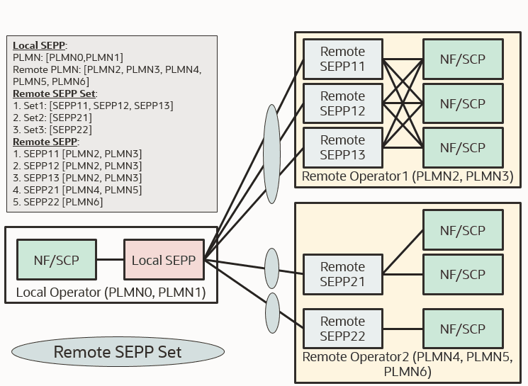
The SEPP can be configured as Local SEPP (the SEPP at the consumer side, cSEPP) and as Remote SEPP (the SEPP at the producer side, pSEPP). To initiate the communication between a Local SEPP and Remote SEPP, the Local and Remote SEPP sides must be configured to have the list of SEPPs that are assigned as primary, secondary, or tertiary SEPPs to support the alternate routing as per the availability of SEPPs. Each Remote SEPP Set must have unique list of PLMNs supported by that particular set.In the above diagram the SEPPs, Remote SEPP Sets, and PLMNs are configured as follows:
- Local SEPP supports PLMN0 and PLMN1.
- Remote SEPP11, SEPP12, and SEPP13 shares the PLMN2 and PLMN3 networks.
- The Remote SEPP11, Remote SEPP12, and Remote SEPP13 are working as primary, secondary and tertiary SEPPs, as they are part of the same remote SEPP set.
- Remote SEPP21 and Remote SEPP22 belongs to the remote operator 2. Remote SEPP 21 supports PLMN4 and PLMN5. Remote SEPP 22 supports PLMN 6.
- Remote SEPP 21 and 22 belongs to same operator, but they are not sharing the same PLMN list. So they are reachable through different remote SEPP sets.
- N32c is interface between the SEPPs for performing initial handshake and negotiating the parameters to be applied for the actual N32 message forwarding. The handshake initiation is modified to support the Multiple PLMN For Local and Remote SEPP.
- N32f is the interface between the SEPPs for forwarding the communication between the NF service consumer and the NF service producer. While sending the request, the plmnid configured at handshake must be validated by comparing the plmnid in the fqdn of the 3gpp-sbi-target-apiRoot or Authority header. Once the plmnid is validated, then the messages are forwarded to the destined NFs.
Note:
The following table lists the Range of RemoteSepp Set and PLMN ID:
Table 3-10 Range of RemoteSepp Set and PLMN ID
| Mode/Parameter | PLMN ID per RemoteSepp | RemoteSepp Set | Local PLMN ID List (Self PLMN) |
|---|---|---|---|
| SEPP Mode |
Minimum = 1 Maximum = 30 |
Minimum = 1 Maximum = 1000 |
Minimum = 1 Maximum = 30
|
RemoteSepp = SEPP in Remote PLMN
RemoteSepp Set =RemoteSepp sets are created per PLMN. It consists of minimum 1 and maximum 3 RemoteSepp in Primary-Secondary-Tertiary mode and used for N32F SBI message routing.
Enable
This feature is the core functionality of SEPP. You do not need to enable or disable this feature. It is enabled by default.
Note:
If plmnList is updated in NrfClient: profile: appProfiles section, after performing the helm-upgrade user needs to restart the NF Management pods (nfmanagement and nfdiscovery) to load the latest profile in NRF.Configure
You can configure the Multiple PLMN support for local and remote SEPP using REST API and CNC Console.
- Configure Multiple PLMN support for local and remote SEPP using REST API: Perform the feature configurations as described Remote SEPP Set and Remote SEPP section in Oracle Communications Security Edge Protection Proxy Rest API Guide.
- Configure Multiple PLMN support for local and remote SEPP using CNC Console: Perform the feature configurations as described in Configuring SEPP using CNC Console.
Observe
For more information about metrics and KPIs, see SEPP Metrics and SEPP KPIs sections.
Maintain
If you encounter alerts at system or application levels, see SEPP Alerts section for resolution steps.
In case the alert still persists, perform the following:
- Collect the logs: For more information on how to collect logs, see Oracle Communications Cloud Native Core Security Edge Protection Proxy Troubleshooting Guide.
- Raise a service request: See My Oracle Support for more information on how to raise a service request.
3.9 Support of TLS for Roaming Hubs and IPX Providers
Oracle SEPP is deployed by both Mobile Network Operators (MNO) and Roaming Hub providers. MNOs deploy SEPP acting as 3GPP 5GC SEPP NEF which enables inter PLMN communication between two networks via N32 interface.
Roaming Hub providers deploy SEPP acting as Roaming Hub enabling inter PLMN communication between MNOs through N32 interface supporting Application Layer Security (ALS) as specified in TS 33.501. Roaming Hub provider is able to deploy SEPP in either of one mode i.e. functionality of 5GC SEPP NF or Roaming Hub. Roaming Hub providers are able to host 5GC SEPP NF functionality for few of the MNO's and host Roaming Hub functionality for rest of the MNOs.
There are scenarios where the user wants to deploy an intermediate proxy. Currently, for SEPP to be a viable proxy 3GPP specifies that a mode is known as PRINS be supported on the Roaming Hub.
PRINS mode has implementation challenges. To overcome this, there is an option where SEPP can be deployed as an interconnect proxy without the use of PRINS. This is commonly called as the Supporting Roaming Hub using TLS mode.
The following diagram represents a high-level overview of Support of TLS for Roaming Hubs and IPX Providers.
Figure 3-13 Roaming Hub Overview

SEPP supports inter PLMN traffic for both SEPP MNO and Roaming Hub modes.
Detailed Description
Figure 3-14 Detailed Description

In previous releases, when operators require to have interconnect with other operators, a Security Edge Protection Proxy allows for the following:
- A single point of entry into and out of the network
- This single point of entry can help in having a single point of interconnect
- Security to networks (not exposing all the NF's to the external network)
- The interconnect operators functions as an aggregator for roaming interconnects.
- The Operators can scale out as interconnect and can enable interconnects to become a roaming HUB.
- To support this, multiple SEPPs can be deployed by a Roaming Hub.
- Each SEPP within the Roaming Hub Provider needs to implement complex routing feature in order to route message from one consumer SEPP to a producer SEPP within the Roaming Hub.
Note:
The following table lists the Range of RemoteSepp Set and PLMN ID:
Table 3-11 Range of RemoteSepp Set and PLMN ID
| Mode/Parameter | PLMN ID per RemoteSepp | RemoteSepp Set | Local PLMN ID List (Self PLMN) |
|---|---|---|---|
| Roaming Hub Mode |
Minimum = 1 Maximum = 20 |
Minimum = 1 Maximum = MaxRSS
The value can be derived from : MaxRSS == (400 – total number of PLMNs used) / Maximum PLMN per RemoteSeppSet |
Minimum = 1 Maximum = 400
Local PLMN is consolidate list of PLMN IDs of all the RemoteSepp(s) associated with this Roaming Hub |
RemoteSepp = SEPP in Remote PLMN
RemoteSepp Set =RemoteSepp sets are created per PLMN. It consists of minimum 1 and maximum 3 RemoteSepp in Primary-Secondary-Tertiary mode and used for N32F SBI message routing.
Enable
This feature is the core functionality of SEPP. You do not need to enable or disable this feature. It is enabled by default.
Configure
You can configure the Support of TLS for Roaming Hubs and IPX Providers feature using REST API, and CNC Console.
- Configure Support of TLS for Roaming Hubs and IPX Providers feature using REST API: Perform the feature configurations as described logging Configurations section in Oracle Communications Security Edge Protection Proxy Rest API Guide.
- Configure Support of TLS for Roaming Hubs and IPX Providers feature using CNC Console: Perform the feature configurations as described in Configuring SEPP using CNC Console.
Observe
For more information about metrics and KPIs, see SEPP Metrics and SEPP KPIs sections.
Maintain
If you encounter alerts at system or application levels, see SEPP Alerts section for resolution steps.
In case the alert still persists, perform the following:
- Collect the logs: For more information on how to collect logs, see Oracle Communications Cloud Native Core Security Edge Protection Proxy Troubleshooting Guide.
- Raise a service request: See My Oracle Support for more information on how to raise a service request.
3.10 Cat-1 Service API Validation Feature
The Cat-1 Service API Validation feature allows the operator to configure the stateless security measures at the SEPP. This feature intends to support this in two ways:
- Check of combination of HTTP Method and Service requested (Example: POST cannot be used in combination with a particular service).
- Allows only certain SBI messages to either egress or ingress the network (Example: AMF to UDM messages)
Design and Architecture
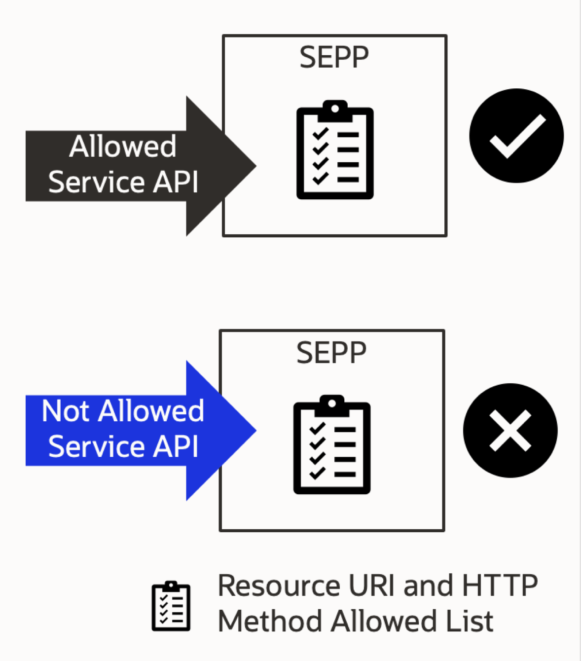
SEPP allows a list of allowed Resource URIs and HTTP Method to be configured. Every Ingress and egress messages is validated against the configured allowed list on P-SEPP and C-SEPP.
The configuration is available at both C-SEPP and P-SEPP. If the Resource URI and HTTP Method matches with the configured one, that Service API is allowed to pass through the SEPP and if the Resource URI and Method in the ingress and egress messages does not matches, then as per the configured action in the error configuration by the user, the Service API is rejected.
Figure 3-15 Security Counter Measure Service
To add a new Resource URI along with HTTP Method which is not present in the Allowed List, add the new Resource URI first in Service API section (on the Main Menu of SEPP in CNC Console GUI) and add it in the Allowed List. The newly added Resource URI and Method automatically be updated in the drop down of Ingress Rule and Egress Rule.
By default the Resource URI list in CNC Console Screen will be populated with some default Resource URIs and HTTP Methods which is user configurable and can be added or deleted as required.
- Multiple Allowed List can be configured by the user.
- Default Allowed List with name Default is configured during SEPP installation.
- An allowed list needs to be configured for a Remote SEPP Set mandatorily.
- Ingress and Egress Rules define the combination of allowed Resource URIs and HTTP Methods.
- Ingress and Egress Action defines the Action, Status Code, and Title to be used in case the Service API is not allowed.
Managing Cat-1 Service API Validation Feature
Enable
You can enable Cat-1 Service API Validation feature using the REST API or CNC Console.
- Enable using REST API: Set Enable Security Counter Measure to True in Security Counter measure Service API Validation Feature State API. For more information about API path, see Oracle Communications Cloud Native Core Security Edge Protection Proxy REST Specification Guide.
- Enable using CNC Console: Set
Enable Service API
                        Validation
to True on the Security Counter Measure page. For more information about enabling the feature using CNC Console, see Security Counter Measure Options.
Configure
You can configure the Cat-1 Service API Validation using REST API and CNC Console.
- Configure Cat-1 Service API Validation using REST API: Perform the feature configurations as described Security Counter Measure Service API Validation, Security Countermeasure Service API Allowed List Name, and Supported Service API's sections in Oracle Communications Security Edge Protection Proxy Rest API Guide.
- Configure Cat-1 Service API Validation using CNC Console: Perform the feature configurations as described in Configuring SEPP using CNC Console.
Observe
For more information about metrics and KPIs, see SEPP Metrics and SEPP KPIs sections.
Maintain
If you encounter alerts at system or application levels, see SEPP Alerts section for resolution steps.
In case the alert still persists, perform the following:
- Collect the logs: For more information on how to collect logs, see Oracle Communications Cloud Native Core Security Edge Protection Proxy Troubleshooting Guide.
- Raise a service request: See My Oracle Support for more information on how to raise a service request.
3.11 Overload Control Feature
Overview
SEPP processes 5G Service Based Interface (SBI) messages using its microservices. To protect the microservices from the overload, SEPP supports Overload Control feature. The feature provided by Ingress Gateway and Perf-Info. This section describes the SEPP support for this feature.
Overload occurs when 100% of the planned capacity is exhausted. It can be due to uneven distribution of traffic towards a given SEPP service instance, network fluctuations leading to traffic bursts, or unexpected high traffic volume at any given point of time. During overload conditions, the service's response time may grow to unacceptable levels, and exhaustion of resources may force service to unexpected behavior or even downtime. Overload control helps to control services downtime and ensures service availability during extreme overload conditions. Using Ingress Gateway and perf-info microservices, SEPP provides options to control network congestion and handle the overload scenarios.
Detailed Description
The perf-info calculates CPU and memory usage. Based on the configured threshold levels, the Perf info applies the threshold level defined. The Ingress Gateway allows or discards incoming requests, based on the overload threshold applied.There are 2 types of discard policies supported; Percentage based and Priority based.
In percentage based discard policy, discard the certain percentage of messages once the traffic is reached threshold level. In priority based discard policy, if SEPP is overloaded, only the high priority messages are processed. Low priority traffic is discarded with the configured error code.
SEPP allows the user to configure the threshold overload levels.
Setting the threshold level
User can configure the threshold level for CPU and Memory usage.
Threshold levels defined are Warning , Minor, Major, and Critical. When values for CPU and Memory reach the configured limits, data is discarded on the basis of configured values for the threshold level defined.
The following table represents the example for threshold set for CPU and memory and the discard values.
Table 3-12 Threshold Level
| Threshold Level | CPU onset | CPU abatement | Memory onset | Memory abatement | Percentage Discard | Priority threshold |
|---|---|---|---|---|---|---|
| Warning | 65 | 60 | 50 | 45 | 0% | 30 |
| Minor | 75 | 70 | 70 | 65 | 5% | 24 |
| Major | 85 | 80 | 80 | 75 | 10% | 15 |
| Critical | 95 | 90 | 90 | 85 | 25% | 10 |
Percentage based discard policy
The percentage based discard policy is applied on the incoming traffic. When
SEPP is overloaded and if the discard scheme is Percentage based, the number of messages
discarded corresponds to the threshold percentage level defined.
In the above diagram, percentage threshold level is set as 10%. Therefore for incoming traffic rate at 100 TPS, 10 messages will be discarded with the configured error code.
Priority based discard policy
The priority based discard policy is applied on the incoming traffic . When application is overloaded and if the discard scheme is priority based, the messages are discarded on the basis of the priority threshold defined. The priority is determined by the "3gpp-sbi-message-priority" header present in the incoming message.
Higher the value of "3gpp-sbi-message-priority" lower is the priority and vice-versa.
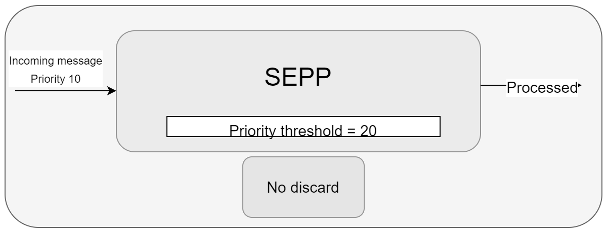
In the above diagram, the threshold priority set is 20 . The incoming message has 3gpp-sbi-message-priority header value as 10. As it is a high priority message, the message will be processed.
 In the above diagram, the threshold priority set is 20. The incoming message
has 3gpp-sbi-message-priority header value as 24 . As it is a low priority message,
the message will be discarded.
In the above diagram, the threshold priority set is 20. The incoming message
has 3gpp-sbi-message-priority header value as 24 . As it is a low priority message,
the message will be discarded.
Managing Overload Control Feature
Enable
This feature is disabled by default.
Note:
This feature is supported only on inter PLMN traffic, that is N32 Ingress Gateway and PN32F-svc.
You can enable the Overload Control feature using the REST API.
- Enable using REST API: Set svcName to <release-name>-pn32f-svc and set enabled to true in Overload Control REST API. For more information about API path, see Oracle Communications Cloud Native Core Security Edge Protection Proxy REST Specification Guide.
Configure
You can configure the feature using REST API:
- Configure using REST API: Perform the feature configurations as described in Oracle Communications Cloud Native Core Security Edge Protection Proxy REST Specification Guide.
Steps to configure overload control
- By default, the feature will be disabled. To enable the feature run
the Overload Control REST API to change the svcName to
<release-name>-pn32f-svc and enabled to
true.
curl -X PUT http://<config-server>:port/sepp/nf-common-component/v1/igw/n32/ocpolicymapping -H 'Content-type: application/json' -d ' { "enabled": true, "mappings": [ { "svcName": "ocsepp-release-pn32f-svc", "policyName": "Policy2" } ], "samplingPeriod": 5000 }' - To define CPU and Memory threshold limits, run the following code.
Change the svcname as done as step
1:
curl -X PUT http://<config-server>:port/sepp/nf-common-component/v1/perf-info/overloadLevelThreshold -H 'Content-type: application/json' -d '
[{
    "svcName": "ocsepp-release-pn32f-svc",
    "metricsThresholdList": [{
        "metricsName": "memory",
        "levelThresholdList": [{
            "level": "Warning",
            "onsetValue": 50,
            "abatementValue": 45
        }, {
            "level": "Minor",
            "onsetValue": 70,
            "abatementValue": 65
        }, {
            "level": "Major",
            "onsetValue": 80,
            "abatementValue": 75
        }, {
            "level": "Critical",
            "onsetValue": 90,
            "abatementValue": 85
        }]
    }, {
        "metricsName": "cpu",
        "levelThresholdList": [{
            "level": "Warning",
            "onsetValue": 65,
            "abatementValue": 60
        }, {
            "level": "Minor",
            "onsetValue": 75,
            "abatementValue": 70
        }, {
            "level": "Major",
            "onsetValue": 85,
            "abatementValue": 80
        }, {
            "level": "Critical",
            "onsetValue": 95,
            "abatementValue": 90
        }]
    }]
}]'
Note:
The above mentioned values are the recommended values for each threshold level. User can configure them as required. - By default the discard policy is Percentage Based. To change the
discard policy to Priority based, run the following code with svcName same as in
step1:
curl -X PUT http://<config-server>:port/sepp/nf-common-component/v1/igw/n32/ocpolicymapping -H 'Content-type: application/json' -d ' { "enabled": true, "mappings": [ { "svcName": "ocsepp-release-pn32f-svc", "policyName": "Policy1" } ], "samplingPeriod": 5000 }' #Policy1 is PriorityBased - By default the error code configured is 429. To change the error
code, change the errorCode and run the following
code:
curl -X PUT http://<config-server>:port/sepp/nf-common-component/v1/igw/n32/errorcodeprofiles -H 'Content-type: application/json' -d ' [ { "name": "error429", "errorCode": 503, "errorCause": "", "errorTitle": "", "errorDescription": "" } ] - To get the details of discard policy defined, run the following
command:
Example:curl -X GET http://<config-server>:port/sepp/nf-common-component/v1/igw/n32/ocdiscardpoliciesDiscardPolicies.json:
[{
"name": "Policy1",
"scheme": "PriorityBased",
"policies": [{
"level": "Warning",
"value": 30,
"action": "RejectWithErrorCode",
"errorCodeProfile": "error429"
},
{
"level": "Minor",
"value": 24,
"action": "RejectWithErrorCode",
"errorCodeProfile": "error429"
},
{
"level": "Major",
"value": 15,
"action": "RejectWithErrorCode",
"errorCodeProfile": "error429"
},
{
"level": "Critical",
"value": 10,
"action": "RejectWithErrorCode",
"errorCodeProfile": "error429"
}
]
},
{
"name": "Policy2",
"scheme": "PercentageBased",
"policies": [{
"level": "Warning",
"value": 0,
"action": "RejectWithErrorCode",
"errorCodeProfile": "error429"
},
{
"level": "Minor",
"value": 5,
"action": "RejectWithErrorCode",
"errorCodeProfile": "error429"
},
{
"level": "Major",
"value": 10,
"action": "RejectWithErrorCode",
"errorCodeProfile": "error429"
},
{
"level": "Critical",
"value": 25,
"action": "RejectWithErrorCode",
"errorCodeProfile": "error429"
}
]
}
]
Note:
- The above are recommended values. The user can change them as per their preference.
- value for Percentage Based policy indicates the percentage of incoming traffic that will be discarded.
- value for Priority Based policy indicates the threshold priority value, equal to or higher which the incoming traffic will be discarded.
- To change the discard policies, run the following command with your
changes in
DiscardPolicies.json:
curl -X PUT http://<config-server>:port/sepp/nf-common-component/v1/igw/n32/ocdiscardpolicies -H 'Content-type: application/json' -d @DiscardPolicies.json
Observe
- oc_ingressgateway_route_overloadcontrol_total
- service_resource_overload_level
- PercentageDiscard
- PriorityDiscard
For more information on Overload Control feature related SEPP Metrics and KPIs, see SEPP Metrics and SEPP KPIs sections.
Maintain
If you encounter alerts at system or application levels, see SEPP Alerts section for resolution steps.
In case the alert still persists, perform the following:
- Collect the logs: For more information on how to collect logs, see Oracle Communications Cloud Native Core Security Edge Protection Proxy Troubleshooting Guide.
- Raise a service request: See My Oracle Support for more information on how to raise a service request.
3.12 Alternate Routing Across Remote SEPPs
In earlier SEPP releases, Consumer SEPP could communicate with single Producer SEPP and if this single Producer SEPP was not available for any reason, n32f traffic would drop and not reach its home PLMN.
The SEPP cannot route to an alternate SEPP when the primary path is down. The reasons for the primary path being down can vary from routing path having issues, to the actual P-SEPP not being up and running. Some of the reasons can be as follows:
- Remote SEPPor NF is not reachable due to network issue
- Remote SEPP or NF unavailable
- There is an internal server error
- Bad request
- FQDN/IP or port is incorrect
- HTTP2 Error codes, 400, 404, 500, 503, and 504
With Alternate Routing Across Remote SEPPs feature, the consumer SEPP routes the n32f traffic messages based on the availability of Primary or Secondary or Tertiary producer SEPPs present in a Remote SEPP Set (sets will be uniquely identified based on the home PLMN).
Feature Overview
The purpose of implementing this feature is to support and provide a reliable path always between two PLMNs through the SEPPs.
Design and Architecture
In this feature, the consumer SEPP end routes the n32f traffic messages based on the availability of Primary or Secondary or Tertiary producer SEPPs present in a set. The following diagram represents the detailed architecture of the Alternate Routing Across Remote SEPPs.
Figure 3-16 Architecture
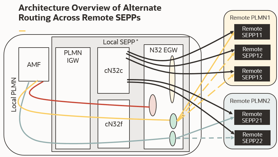
- The remote SEPP sets are created per PLMN. In this diagram there are two remote sets, remote SEPP set for Home PLMN1 and remote SEPP set for Home PLMN2.
- These Remote SEPP sets can vary from 1 to N (unique for each PLMN).
- Each set can have up to three producer SEPP's based on their priority as primary, secondary, or tertiary.
- N32 EGW routes each n32f traffic message to the producer based on the priority assigned in the Remote SEPP.
- N32 EGW first routes each n32f traffic message towards primary SEPP, if it is not available it then routes to secondary SEPP, and similarly towards the tertiary SEPP.
- The call will be dropped only if primary, secondary, and tertiary SEPPs are not available. This increases the reliability of the calls.
Enable
This feature is the core functionality of SEPP. You do not need to enable or disable this feature. It is enabled by default.
Configure
You can configure the Alternate Routing Across Remote SEPPs using REST API, and CNC Console.
- Configure Alternate Routing Across Remote SEPPs using REST API: Perform the feature configurations as described in Remote SEPP Set section in Oracle Communications Cloud Native Core, Security Edge Protection Proxy REST Specification Guide.
Default Routes
When SEPP is installed, the following three default routes are created on n32-egress-gateway:
- N32c with path set to /n32c-handshake/**: This route helps in the routing of n32c handshake exchange-capability message without apiPrefix.
- N32d with path set to /*/n32c-handshake/**: This route helps in the routing of n32c handshake exchange-capability message with apiPrefix.
- ocseppRejectAll (default route): This is the default route. If any message except Handshake and n32f arrives, it is dropped at Egress Gateway and is not routed towards the Producer SEPP.
Figure 3-17 Default Routes
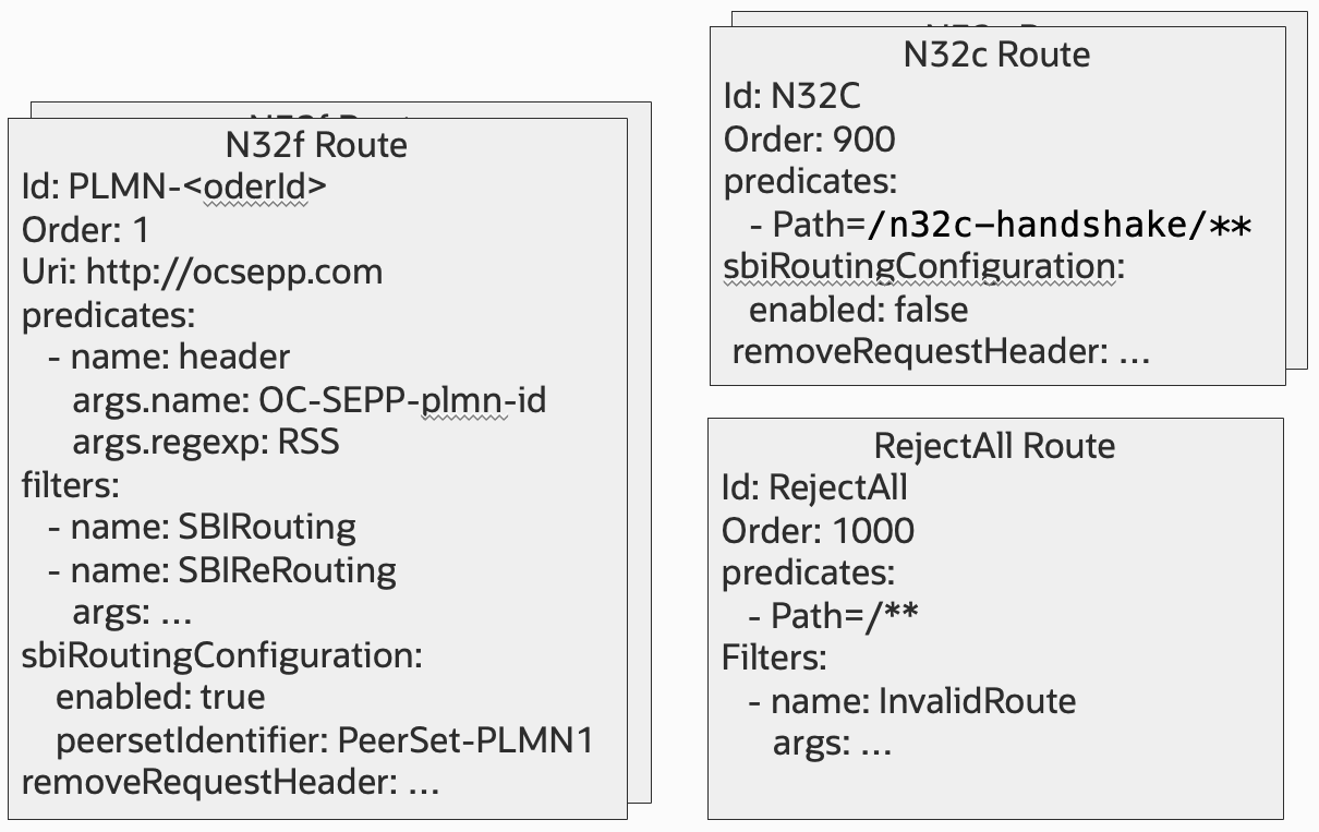
Example of the default route created automatically on n32-egress-gateway:
routesconfiguration": [{"id": "ocseppRejectAll", "uri": "https://ocsepp.com", "order": 903, "filters": [{"args": {"errorCodeOnInvalidRoute": "500", "errorCauseOnInvalidRoute": "No Matching Route.", "errorTitleOnInvalidRoute": "No Matching Route.", "errorDescriptionOnInvalidRoute": "No Matching Route."}, "name": "InvalidRouteFilter"}], "predicates": [{"args": {"pattern": ""}, "name": "Path"}]}, {"id": "n32c", "uri": "https://ocsepp.com", "order": 901, "predicates": [{"args": {"pattern": "/n32c-handshake/**"}, "name": "Path"}]}, {"id": "n32d", "uri": "https://ocsepp.com", "order": 902, "predicates": [{"args": {"pattern": "/*/n32c-handshake/**"}, "name": "Path"}]},Routes for SBI Message (n32f interface)
- Remote SEPP is added at initiator and responder side. Once security capability procedure is successful, Peer is added at n32-egress-gateway.
- Remote SEPP Set is added to SEPP having information about primary, secondary, and tertiary SEPPs. Based on the Remote SEPP Set information, n32-egress-gateway also configures the Peer Set at its end, and tries to route the N32f messages based on the priority configured in the Peer Set.
- N32f route helps in routing of n32f traffic messages towards producer SEPP based on the PLMN of the Producer SEPP.
The user configurable Helm parameters and can be configured through
ocsepp/charts/config-mgr-svc/values.yaml file.
For more information on the Helm parameters, see the config-mgr-svc section of Oracle Communications Cloud Native Core, Security Edge Protection Proxy Installation, Upgrade, and Fault Recovery Guide.
{"id": "plmn-357", "uri": "https://ocsepp.com", "order": 357, "filters": [{"args": {"errorHandling": [{"priority": 2, "actionSet": "action_0", "actionSet": "criteria_1"}, {"priority": 1, "actionSet": "action_0", "errorCriteriaSet": "criteria_0"}], "peerSetIdentifier": "RS-1", "customPeerSelectorEnabled": true}, "name": "SbiRouting"}, {"args": {"name": "OC-SEPP-PLMN-ID"}, "name": "RemoveRequestHeader"}], "metadata": {"httpRuriOnly": false, "httpsTargetOnly": false, "sbiRoutingEnabled": true}, "predicates": [{"args": {"header": "OC-SEPP-PLMN-ID", "regexp": "RS-1"}, "name": "Header"}]}], "forwardheaderdetails": {"enabled": false, "forwardHeaderValue": ""}Alternate Routing Flow
When the SBI message reached n32-egress-gateway, the relevant route is selected. The traffic is routed towards the primary peer mentioned in the peerset associated with the route. On receiving the response from primary peer:
- If the response is successful, message is routed towards Remote SEPP.
- If the response is an error response, the response is validated against the errorCriteriaSet mentioned in the route. If the error received matched the criteria mentioned in the criteria set, action is performed on the basis of actionSet.
Figure 3-18 Alternate Routing Flow Chart Representation
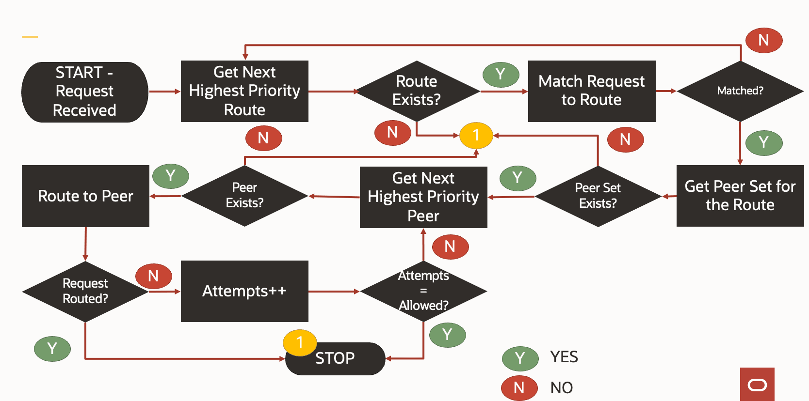
Response Validation against the Error Handling
The error handling section within the SbiRouting filter is an array of mapping between criteriaset and actionset, tagged with a priority. It is similar to peer and peerset configurations tagging. The criteriaset and actionset ids are tagged in the error handling section along with a priority for each mapping. The actual criteriaset and actionset configuration has to be done in sbiRoutingErrorCriteriaSets and sbiRoutingErrorActionSets respectively.
sbiRoutingErrorCriteriaSets
It is a combination of HTTP method and HTTP status code or HTTP method and exception. When an error response is received, HTTP status code and HTTP method or exception is received in the response is validated with the configured values.
- If the match is found, action is taken on the basis of erroractionset configuration.
- If the match is not found, error response is sent to the originating NF.
"sbiroutingerrorcriteriasets": [{"id": "criteria_1", "method": ["GET", "POST", "PUT", "DELETE", "PATCH"], "response": {"statuses": [{"status": [400, 404], "statusSeries": "4xx"}, {"status": [500, 503, 504], "statusSeries": "5xx"}]}}, {"id": "criteria_0", "method": ["GET", "POST", "PUT", "DELETE", "PATCH"], "exceptions": ["java.util.concurrent.TimeoutException", "java.net.SocketException", "java.net.SocketTimeoutException", "java.net.UnknownHostException", "java.net.ConnectException", "java.net.NoRouteToHostException"]}SbiRoutingErrorActionSets
After the criteriaset conditions is validated and met, the corresponding actionset is selected to decide what will be the next course of action.
- action: SEPP currently supports only reroute action which means try secondary or tertiary peer when the error is received from primary or secondary peer.
- attempts: Maximum no of retries to either same or different
peer in case of errors or failures from received backend.
- The action is reroute and no of reroute attempts is 2. Hence, the request would be rerouted to the secondary peer of peerset and then the same steps would be repeated for tertiary once the error response from secondary peer is recieved.
- If only primary peer is configured and if an error is received, three retries are attempted on the primary peer.
- If the primary and secondary peers are configured and if an error is received, the retries are attempted on the secondary peer.
Note:
To enable alternate routing feature, changealternateRoute.sbiReRoute.sbiRoutingErrorActionSets[].Attemptsparameter value to 2. This will allow switching from primary to secondary to tertiary remote SEPPs. - blacklist: At present, this is not used on n32-egress-gateway.
"sbiroutingerroractionsets": [{"id": "action_0", "action": "reroute", "attempts": 2, "blacklist": {"enabled": false, "duration": 60000}}]Observe
For more information about metrics and KPIs, see SEPP Metrics and SEPP KPIs sections.
Maintain
If you encounter alerts at system or application levels, see SEPP Alerts section for resolution steps.
In case the alert still persists, perform the following:
- Collect the logs: For more information on how to collect logs, see Oracle Communications Cloud Native Core, Security Edge Protection Proxy Troubleshooting Guide.
- Raise a service request: See My Oracle Support for more information on how to raise a service request.
3.13 Server Header support
SEPP supports server header in the error responses generated for SEPP services. Using the server header, the user can find out if the error is generated either by the SEPP or some other NF. As per 3gpp specs, format of server-header is SEPP-<fqdn>.
If an error condition occurred at SEPP, SEPP services adds the server header in the error response message. This is added to inform the user that error is generated by SEPP. All the intra PLMN traffic in SEPP is received by plmn-ingress-gateway and inter PLMN traffic is handled by N32-ingress-gateway. If any of the ingress-gateway in SEPP is not reachable or in error state, error response would not contain server-header parameter.
Gateways also support adding server-header for which user has to enable server-header through helm configuration.
Error scenario examples: n32f-context not found, 3gpp-header is not in correct format, Ingress Gateway is down.
Helm Configuration
Configure using helm: To configure server header at Egress Gateway, you need to perform the helm configurations:
# All attributes under "serverHeaderDetails" will need to be configured only if "serverHeaderConfigMode" is set as "HELM"
  serverHeaderDetails:
    # If enabled at Global level, Global conf will be used by default if no conf exists at Route level.
    enabled: true
    # Mandatory attribute if not defined at Route level. By default used for Global level conf. Value need to be one among "errorCodeSeriesList" resource defined below.
    errorCodeSeriesId: E1
    configuration:
       # Mandatory attribute. This value is common across Global and Route level conf. If not defined, server header will not be included in response.
      nfType: SEPP
      # Optional attribute. This value is common across Global and Route level conf. If not defined, only "nfType" will be used for server header value.
      nfInstanceId: 9faf1bbc-6e4a-4454-a507-aef01a101a06

  # Use below configuration to define errorCodeSeries list
  errorCodeSeriesList:
    # Value of "id" attribute will need to used for assigning "errorCodeSeriesId" either at Global or Route level conf for Server header.
  - id: E1
    errorCodeSeries:
      # Possible values for "errorSet" attribute: 5xx, 4xx, 3xx, 2xx, 1xx
    - errorSet: 4xx
      # Possible values include all error codes in the respective HttpSeries(Ex: 4xx) value assinged for "errorSet". Use single value of -1 if all error codes are to be considered.
      errorCodes:
      - 400
      - 408
      - 404
    - errorSet: 5xx
      errorCodes:
      - 500
      - 503
      - 504
  - id: E2
    errorCodeSeries:
    - errorSet: 4xx
      errorCodes:
      - -1
3.14 SEPP MNO functionality Support
SEPP supports the following interfaces:
- N32-c interface ( TLS mode only)
- N32-f interface (TLS mode only)
- TLS 1.2
When operators require to have interconnect with other operators, a Security Edge Protection Proxy allows for the following:
- A single point of entry into and out of the network
- This single point of entry can help in having a single point of interconnect
- Security to networks (not exposing all the NF's to the external network)
Additionally the SEPP can assist is being a single point of interconnect to multiple networks on the core and inter-PLMN side. To assist in such a deployment, the SEPP has been modified to support the following:
- Multiple Remote SEPPs on the egress side towards other PLMNs.
- Multiple core networks can be configured to route to the SEPP.
- The N32-c handshake procedures have also been modified to support multiple N32-c handshakes with other roaming partner SEPPs, that is the N32-f interfaces can be established across multiple partners from a single SEPP.
The following diagram depicts the topology for SEPP MNO functionality Support.
Figure 3-19 Topology for SEPP MNO functionality
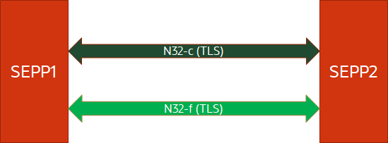
Enable
This feature is the core functionality of SEPP. You do not need to enable or disable this feature. It is enabled by default.
Configure
- Configure SEPP MNO functionality using REST API: Perform the feature configurations as described Remote SEPP section in Oracle Communications Security Edge Protection Proxy Rest API Guide.
- Configure SEPP MNO functionality using CNC Console: Perform the feature configurations as described in Configuring SEPP using CNC Console.
#Set the local profile for the SEPP Instance.

localProfile:
    name: "SEPP-1"
    plmn:
      mcc: "311"
      mnc: "282"
    domain: "oracle.com"
    interPlmnFqdn: "sepp1.inter.oracle.com"
    intraPlmnFqdn: "ocsepp-plmn-ingress-gateway.DEPLOYMENT_NAMESPACE"
    supportedSecurityCapabilityList:
     - "TLS"
    apiPrefix:  ""
    retryInterval: 300000
    maxRetry: -1
    nfInstanceId: "9faf1bbc-6e4a-4454-a507-aef01a101a06"

   #configuration in n32-egress-gateway, n32-ingress-gateway, plmn-egress-gateway, plmn-ingress-gateway section in ocsepp-custom-values.yaml file

 ssl:
     tlsVersion: TLSv1.2
sepp:
forwardProxy: true
egressProxyHeader: X-Next-Hop
customAuthorityHeader: X-Next-Hop-Authority
removeUnusedProxyAfter: 30
# set true only if sepp.forwardProxy -> true,otherwise it wont have effect
tlsConnectionMode: true
Observe
For more information on support of N32-c and N32-f interface feature metrics and KPIs, see SEPP Metrics and SEPP KPIs sections.
Maintain
If you encounter alerts at system or application levels, see SEPP Alerts section for resolution steps.
In case the alert still persists, perform the following:
- Collect the logs: For more information on how to collect logs, see Oracle Communications Cloud Native Core Security Edge Protection Proxy Troubleshooting Guide.
- Raise a service request: See My Oracle Support for more information on how to raise a service request.
3.15 Dedicated Gateways for IntraPLMN and InterPLMN Traffic
In the earlier releases, a single gateway was used to support both intraPLMN and interPLMN traffic. This led to performance related issues in supported capacity and error handling procedures. To overcome these issues, the architecture was modified. The modification involves establishing dedicated set of gateways for intraPLMN traffic and interPLMN traffic. It also involves optimization of resources to prevent utilization of more resources by these dedicated gateways.This brings in flexibility of scaling the resources independently based on either intraPLMN traffic or interPLMN traffic.
The following diagram depicts the topology for dedicated gateways for IntraPLMN InterPLMN traffic.
Figure 3-20 Dedicated gateways for IntraPLMN InterPLMN traffic
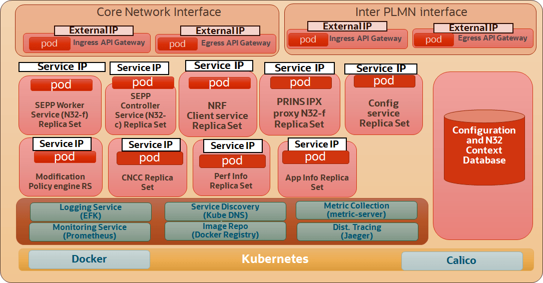
Enable
This feature is the core functionality of SEPP. You do not need to enable or disable this feature. It is enabled by default.
Configure
You can configure the Dedicated Gateways for IntraPLMN and InterPLMN traffic using helm parameters.
Observe
For more information on dedicated gateways for IntraPLMN and InterPLMN traffic feature metrics and KPIs, see SEPP Metrics and SEPP KPIs sections.
Maintain
If you encounter alerts at system or application levels, see SEPP Alerts section for resolution steps.
In case the alert still persists, perform the following:
- Collect the logs: For more information on how to collect logs, see Oracle Communications Cloud Native Core Security Edge Protection Proxy Troubleshooting Guide.
- Raise a service request: See My Oracle Support for more information on how to raise a service request.
3.16 Support for Core Networks with or without SCP
The SEPP can be deployed in networks where SCP is deployed. Routing rules in such scenarios changes. To handle such deployments, a configuration is now provided at the Home SEPP to assist in identifying if the SEPP must route the message to the intended producer or just forward it to the SCP (if deployed in the network) such that the SCP could take the decision to route to the right producer.
Enable
This feature can be enabled or disabled though HELM. The configuration must be set in PLMN Egress gateway section.
Configure
You can configure the Support for Core Networks with or without SCP using helm parameters:
Configuring using Helm parameters
    routesConfig:
  - id: scp_via_proxy
    uri: http://request.uri
    path: /**
    order: 1
    metadata:
      httpsTargetOnly: false
      httpRuriOnly: false
      sbiRoutingEnabled: true
Observe
For more information on Support for Core Networks with or without SCP feature metrics and KPIs, see SEPP Metrics and SEPP KPIs sections.
Maintain
If you encounter alerts at system or application levels, see SEPP Alerts section for resolution steps.
In case the alerts still persists, perform the following:
- Collect the logs: For more information on how to collect logs, see Oracle Communications Cloud Native Core Security Edge Protection Proxy Troubleshooting Guide.
- Raise a service request: See My Oracle Support for more information on how to raise a service request.
3.17 Support for Networks with/without 3GPP-SBI-Target-API-Root Header
There are some networks which may not be supporting the Rel 16 header 3GPP-SBI-Target-Apiroot header. In such scenarios, SEPP being deployed at the edge of the network is required to make the routing possible in the core network. SEPP modifies the respective headers such that routing doesn't fail in the core network.
There are two possible scenarios:
- Network that is sending in the request does not use the
3GPP-SBI-Target-Apiroot header, however the core Network behind the SEPP will
require this header.
In this case the SEPP sets the 3GPP-SBI-Target-Apiroot header to the intended producer by using the value presented to it in the authority header.
The following diagram represents this scenario:
Figure 3-21 SEPP sets the 3GPP-SBI-Target-Apiroot header
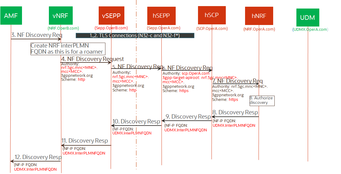
- Network that is sending in the request uses the 3GPP-SBI-Target-Apiroot header, however the core network behind the SEPP will not be able to understand this header.
In this case the SEPP removes the 3GPP-SBI-Target-Apiroot header and set the intended producer in the authority header.
Figure 3-22 SEPP removes the 3GPP-SBI-Target-Apiroot header
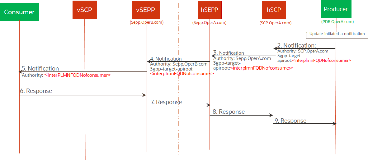
Enable
This feature is enabled by default. This is on the basis of query consumer NF is sending to producer NF.
Configure
You can configure the Support for networks with/without 3GPP-SBI-Target-API-Root header using helm parameters:
Configuring using Helm parameterssbiRouting:
# Default scheme applicable when 3gpp-sbi-target-apiroot header is missing
sbiRoutingDefaultScheme: https
In pn32f svc ->
configs:
is3gppSbiTargetApiRootSchemeHttp: trueObserve
For more information on Support for networks with/without 3GPP-SBI-Target-API-Root header feature metrics and KPIs, see SEPP Metrics and SEPP KPIs sections.
Maintain
If you encounter alerts at system or application levels, see SEPP Alerts section for resolution steps.
In case the alert still persists, perform the following:
- Collect the logs: For more information on how to collect logs, see Oracle Communications Cloud Native Core Security Edge Protection Proxy Troubleshooting Guide.
- Raise a service request: See My Oracle Support for more information on how to raise a service request.
3.18 DNS Support for Remote SEPP Resolution
SEPP to SEPP communication was enforced through configuring the IP address for the far end SEPP. Operators may choose to use a DNS instead and so the SEPP must use the DNS and resolve the IP address of the far end SEPP. This feature allows configuring only the FQDN for the far end SEPP and subsequently needing DNS resolution for identifying the IP address. This feature enhances flexibility to operators now use DNS instead of providing a static IP address.
Managing DNS Support for Remote SEPP Resolution
Enable
This feature is the core functionality of SEPP. You do not need to enable or disable this feature. It is enabled by default.
Configure
DNS configuration can be done in Kubernetes DNS of the cluster. No HELM or REST based configurations are required.
Observe
For more information on DNS support for remote SEPP resolution feature metrics and KPIs, see SEPP Metrics and SEPP KPIs sections.
Maintain
If you encounter alerts at system or application levels, see SEPP Alerts section for resolution steps.
In case the alert still persists, perform the following:
- Collect the logs: For more information on how to collect logs, see Oracle Communications Cloud Native Core Security Edge Protection Proxy Troubleshooting Guide.
- Raise a service request: See My Oracle Support for more information on how to raise a service request.
3.19 NRF Interface Registration and Deregistration
The Network Repository Function (NRF) stores all the information about NFs. SEPP supports registering into the NRF and deregistering from the NRF when required. This allows for NFs to discover the SEPP when required for routing interPLMN traffic.
The following diagram depicts the topology for NRF Interface Registration & Reregistration.
Figure 3-23 NRF Interface Registration & Reregistration.
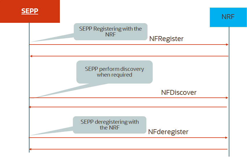
Enable
 nfName: sepp
# Global control to enable/disable deployment of NF Discovery service, enable it if on demand discovery of NF is required.
nrfClientNfDiscoveryEnable: true
# Global control to enable/disable deployment of NF Management service.
nrfClientNfManagementEnable: true
Configure
You can configure the NRF Interface Registration and Deregistration using helm parameters:
Configuring using Helm parametersprofile:
[appcfg]
primaryNrfApiRoot= http://10.75.236.102:31294 #NRF Ingress Gateway IP
secondaryNrfApiRoot=
nrfScheme=http
retryAfterTime=PT120S
nrfClientType=SEPP
nrfClientSubscribeTypes=
appProfiles= [{"nfInstanceId":"9faf1bbc-6e4a-4454-a507-aef01a101a06","nfType":"SEPP","nfStatus":"REGISTERED","fqdn":"ocsepp-release-plmn-ingress-gateway.DEPLOYMENT_NAMESPACE","scheme":"http"}]
deploymentNrfClientService:
# Services to be monitored by performance service
# If no services are to be monitored, envNfNamespace,envNfType,envConsumeSvcName can be left blank
envNfNamespace: csepp
envNfType: 'sepp'
envConsumeSvcName: 'appinfo'
# Service to be monitored by appinfo. We can add a specific SEPP service name
core_services:
sepp: []Observe
For more information on NRF Interface Registration and Deregistration metrics and KPIs, see SEPP Metrics and SEPP KPIs sections.
Maintain
If you encounter alerts at system or application levels, see SEPP Alerts section for resolution steps.
In case the alert still persists, perform the following:
- Collect the logs: For more information on how to collect logs, see Oracle Communications Cloud Native Core Security Edge Protection Proxy Troubleshooting Guide.
- Raise a service request: See My Oracle Support for more information on how to raise a service request.
3.20 Helm Validation Framework
SEPP supports helm validation framework enhancement.This enahancement is
supported to validate the values in a custom_values.yaml file with JSON
schemas.
Table 3-13 Types of Validation checks
| Types of Validation checks | Example |
|---|---|
| Requirement checks | An API_KEY environment variable is set |
| Type validation | The image tag is a string such as "1.5" and not the number 1.5 |
| Range validation | The value for a CPU utilization percentage key is between 1 and 100 |
| Constraint Validation | The pullPolicy is IfNotPresent, Always, or Never. The URL has the format http(s)://<host>:<port> custom_values.yaml |
- helm install
- helm upgrade
- helm lint
- helm template
With Helm 3, user can create a file called values.schema.json which
allows to set value requirements and constraints in a single location.
The values.schema.json file is written using the JSON
Schemavocabulary. According to json-schema.org, JSON Schema is a vocabulary that
allows you to annotate and validate JSON documents.
{
   "$schema": "http://json-schema.org/draft-07/schema",
   "required": [
       "image",
       "serviceType",
       "port"
   ],
   "properties": {
       "image": {
           "type": "object",
           "required": [
               "repository",
               "tag"
           ],
           "properties": {
               "repository": {
                   "type": "string"
               },
               "tag": {
                   "type": "string"
               }
           }
       },
       "serviceType": {
           "type": "string",
           "enum": ["ClusterIP", "LoadBalancer"]
       },
       "port": {
           "type": "integer",
           "minimum": 8080
       }
   }
}
This example provides a schema for the values image.repository, image.tag, serviceType, and port. This can be seen by reviewing the keys under the properties keyword.
This example also uses the required, type, enum, and minimum keywords, which are explained in the following sections.
Required
The required keyword is used to fail chart rendering if specific values are not provided.
"required": [
       "image",
       "serviceType",
       "port"
],$ helm template validation-test test-chart
Error: values don't meet the specifications of the schema(s) in the following chart(s):
test-chart:
- (root): image is required
- (root): serviceType is required
- (root): port is required"image": {
"type": "object", - image: Invalid type. Expected: object, given: string "serviceType": {
"type": "string",
"enum": ["ClusterIP", "LoadBalancer"]
},$ helm template validation-test test-chart --set serviceType=NodePort
Error: values don't meet the specifications of the schema(s) in the following chart(s):
test-chart:
- serviceType: serviceType must be one of the following: "ClusterIP", "LoadBalancer""port": {
"type": "integer",
"minimum": 8080
}$ helm template validation-test test-chart --set port=8000
Error: values don't meet the specifications of the schema(s) in the following chart(s):
test-chart:
- port: Must be greater than or equal to 8080/1There are other keywords which can be used for validating input, including (but not limited to):
- maximum: Set a maximum threshold for a numeric value
- pattern: Set a regex that a value must conform to
- additionalProperties: Determines if the user can provide values that are not defined in the values.schema.json file. By default, users can provide any additional value without restriction, but this would not impact chart rendering if the additional value isn’t used in your templates.
Note:
The helm validation framework is enabled by default for helm v3. To disable the feature, the user has to deletevalues.schema.json file
from the charts folder.
3.21 Subject Alternate Name(SAN) Validation
SAN ( Subject Alternate Names) validation validates whether the SAN in the SEPP certificate matches with the FQDN in the Remote SEPP.
In earlier releases, the SAN Validation is a mandatory configuration for the regular SEPP deployments.
With this enhancement, the SAN validation is made optional. By making SAN validation option, user get the flexibility to bypass this check.
-
sanValidationRequiredis set to false in the roaming partner configuration. This disables san validation for the specific roaming partner. -
sanValidationRequiredis set to false in helm configuration. This disables san validation for all the Remote SEPPs.
Managing Subject Alternate Name(SAN) Validation Feature
Enable
Subject Alternate Name(SAN) Validation Feature is enabled by default.You can disable Subject Alternate Name(SAN) Validation feature using the helm parameters and REST API or CNC Console .
- To disable the feature, set
sanValidationRequiredtoFalsein the ocsepp-custom-values-<version>.yaml file. - Disable using REST API: Set
sanValidationRequiredtoFalsein Remote SEPP. For more information about API path, see Oracle Communications Cloud Native Core Security Edge Protection Proxy REST Specification Guide. - Disable using CNC Console: Set
sanValidationRequiredtoFalseon the Remote SEPP page. For more information about enabling the feature using CNC Console, see Configuring SEPP using CNC Console. -
SAN Validation Enable/Disable Table
Value of sanValidationRequired in HELM Value of sanValidationRequired in REST API/ CNC Console (Remote SEPP ) SAN Validation of incoming N32C handshake request TRUE TRUE SAN Validation occurs TRUE FALSE No SAN Validation FALSE TRUE No SAN Validation FALSE FALSE No SAN Validation
Observe
For more information about metrics and KPIs, see SEPP Metrics and SEPP KPIs sections.
Maintain
If you encounter alerts at system or application levels, see SEPP Alerts section for resolution steps.
In case the alert still persists, perform the following:
- Collect the logs: For more information on how to collect logs, see Oracle Communications Cloud Native Core Security Edge Protection Proxy Troubleshooting Guide.
- Raise a service request: See My Oracle Support for more information on how to raise a service request.
3.22 NF Authentication using TLS certificate
HTTPS enables end to end encryption of messages to ensure security of data. HTTPS requires creation of TLS (Mutual TLS by 2 way exchange of ciphered keys).
Managing NF Authentication using TLS Certificate
Steps to Enable HTTPS in SEPP
Certificate CreationTo create certificate user must have the following files:
- ECDSA private key and CA signed certificate of OCNRF (if initial algorithm is ES256)
- RSA private key and CA signed certificate of OCNRF (if initial algorithm is RS256)
- TrustStore password file
- KeyStore password file
- CA certificate
Secret Creation
$ kubectl create secret generic ocseppaccesstoken-secret --from-file=ecdsa_private_key_pkcs8.pem --from-file=rsa_private_key_pkcs1.pem
      --from-file=trustStorePassword.txt --from-file=keyStorePassword.txt --from-file=ecdsa_ocsepp_certificate.crt--from-file=desertification -n
    ocsepp
Certificate and Key Exchange
Once the connection is established, both parties can use the agreed algorithm and keys to securely send messages to each other. The handshake has 3 main phases:
- Hello
- Certificate Exchange
- Key Exchange
- Hello: The handshake begins with the client sending a ClientHello message. This contains all the information the server needs in order to connect to the client via SSL, including the various cipher suites and maximum SSL version that it supports. The server responds with a ServerHello, which contains similar information required by the client, including a decision based on the client’s preferences about which cipher suite and version of SSL will be used.
- Certificate Exchange: Now that contact has been established, the server has to prove its identity to the client. This is achieved using its SSL certificate, which is a very tiny bit like its passport. An SSL certificate contains various pieces of data, including the name of the owner, the property (Example: domain) it is attached to, the certificate’s public key, the digital signature and information about the certificate’s validity dates. The client checks that it either implicitly trusts the certificate, or that it is verified and trusted by one of several Certificate Authorities (CAs) that it also implicitly trusts. The server is also allowed to require a certificate to prove the client’s identity, but this only happens in very sensitive applications.
- Key Exchange: The encryption of the actual message data exchanged by the client and server will be done using a symmetric algorithm, the exact nature of which was already agreed during the Hello phase. A symmetric algorithm uses a single key for both encryption and decryption, in contrast to asymmetric algorithms that require a public/private key pair. Both parties need to agree on this single, symmetric key, a process that is accomplished securely using asymmetric encryption and the server’s public/private keys.
The client generates a random key to be used for the main, symmetric algorithm. It encrypts it using an algorithm also agreed upon during the Hello phase, and the server’s public key (found on its SSL certificate). It sends this encrypted key to the server, where it is decrypted using the server’s private key, and the interesting parts of the handshake are complete. The parties are identified that they are talking to the right person, and have secretly agreed on a key to symmetrically encrypt the data that they are about to send each other. HTTP requests and responses can be sent by forming a plain text message and then encrypting and sending it. The other party is the only one who knows how to decrypt this message, and so Man In The Middle Attackers are unable to read or modify any requests that they may intercept.
SEPP supports following cipher suites
- TLS_ECDHE_ECDSA_WITH_AES_256_GCM_SHA384
- TLS_ECDHE_RSA_WITH_AES_256_GCM_SHA384
- TLS_ECDHE_RSA_WITH_CHACHA20_POLY1305_SHA256
- TLS_DHE_RSA_WITH_AES_256_GCM_SHA384
- TLS_ECDHE_ECDSA_WITH_AES_128_GCM_SHA256
- TLS_ECDHE_RSA_WITH_AES_128_GCM_SHA256
HTTPS Encrypted Communication
Once the HTTPS handshake is complete all communications between the client and the server are encrypted. This includes the full URL, data (plain text or binary), cookies and other headers.
The only part of the communication not encrypted is what domain or host the client requested a connection. This is because when the connection is initiated an HTTP request is made to the target server to create the secure connection. Once HTTPS is established the full URL is used.
This initialization only needs to occur once for each unique connection. This is why HTTP/2 has a distinct advantage over HTTP/1.1 since it multi-plexes connections instead of opening multiple connections.
Helm Configuration to enable HTTPS on SEPP: #Enabling it generates key and trust store for https support
initssl: true (Note: secret has to be created if its set to true)
#If true opens https port on egress gateway
enableincominghttps: false
#Enabling it egress makes https request outside
enableoutgoinghttps: true
(Note: initssl should be set to true if either enableincominghttps or enableoutgoinghttps is enabled )
#KeyStore and TrustStore related private key and Certificate configuration (Note: The configuration names specified should be same as the file names specified when creating secret)
privateKey:
k8SecretName: ocsepp-n32-secret
k8NameSpace: ocsepp
rsa:
fileName: rsa_private_key_pkcs1.pem
certificate:
k8SecretName: ocsepp-n32-secret
k8NameSpace: ocsepp
rsa:
fileName: ocsepp.cer
caBundle:
k8SecretName: ocsepp-n32-secret
k8NameSpace: ocsepp
fileName: caroot.cer
keyStorePassword:
k8SecretName: ocsepp-n32-secret
k8NameSpace: ocsepp
fileName: key.txt
trustStorePassword:
k8SecretName: ocsepp-n32-secret
k8NameSpace: ocsepp
fileName: trust.txt
initialAlgorithm: RS256
3.23 SEPP Message Feed Feature
SEPP supports copying of the incoming and outgoing messages passing through Ingress and Egress Gateways to a Data Director. Data Director receives the messages from Gateways with a correlation-id and feeds the data securely to an external monitoring system.
The correlation-id in the messages is used as a unique identifier for every transaction. If the request does not have the correlation-id, the Gateway generates the correlation-id and then passes it to Data Director.
Upon receiving an Ingress Gateway request containing a correlation-Id, the SEPP microservices include this correlation-Id in upcoming related Egress Gateway requests that may be generated by the SEPP based on the Ingress Gateway transaction.
Overview
In order to capture incoming and outgoing traffic, there are four tapping points for Ingress Gateway and Egress Gateway.
Figure 3-24 Overview of Message Feed
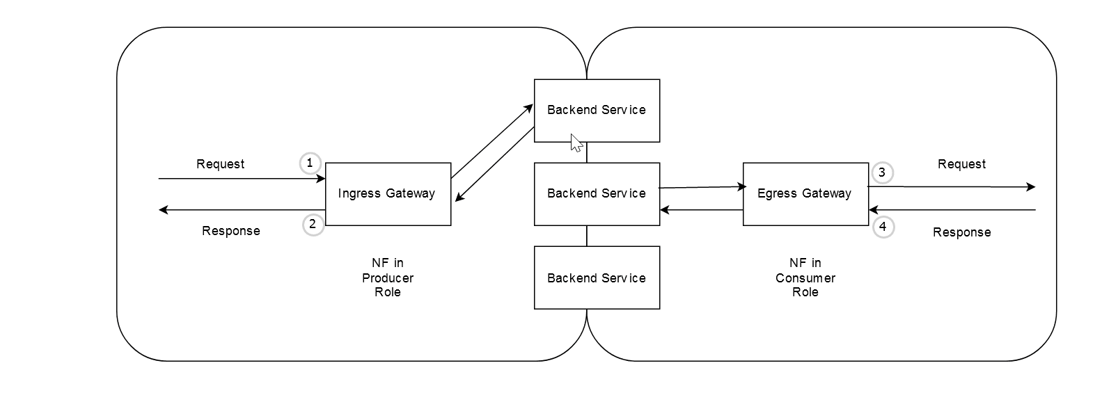
Ingress Gateway Tapping point
- As soon as the request arrives at Ingress Gateway, but before passing through the chain of filters for post-processing.
- When the response is about to be sent by Ingress Gateway to the
consumer NF, after all the post-processing is done by the chain of filters on the
response.
Egress Gateway Tapping point
- After the request is received at Egress Gateway and and has undergone preprocessing and before the request is sent out of Egress Gateway to the producer NF.
- As soon as the response is received at Egress Gateway and before passing it through the chain of filters for post-processing.
In above diagram, 1, 2, 3, and 4 indicate the tapping points at which gateways copy the messages. The message copy can be configured and enabled/disabled in pairs for points (1, 2) and points (3, 4).
The following diagram represents the SEPP representation of Message feed feature:
Figure 3-25 SEPP representation of Message Feed feature
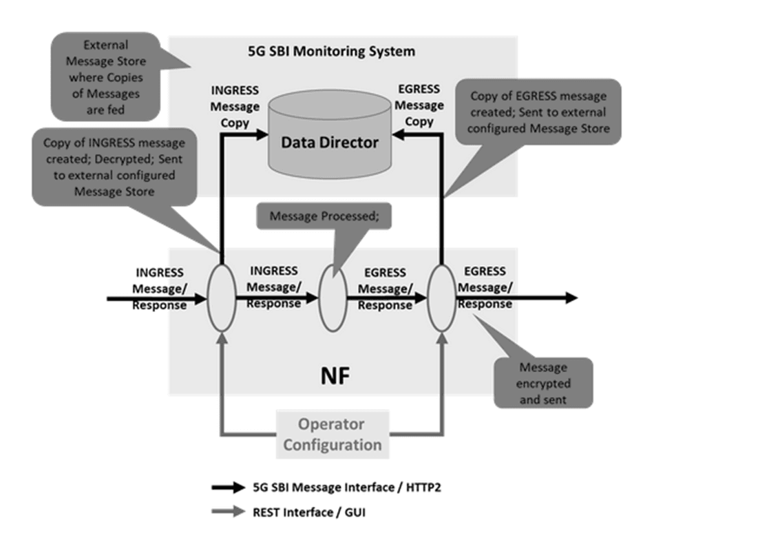
Detailed Description
The following diagram indicates the detailed view of message feed feature in SEPP:
Figure 3-26 Detailed view of message feed feature in SEPP
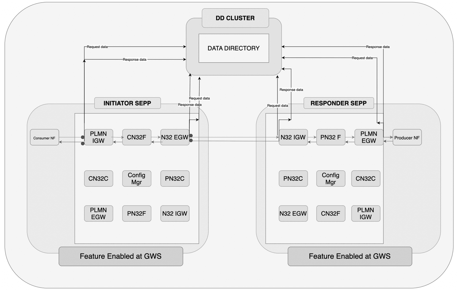
- When SEPP receives an incoming message at the Ingress Gateway, before processing the message, the data sends to the DD.
- After processing the request at DD, the request is sent towards the SEPP microservices which forward to the Egress Gateway.
- After the message has been processed at the Egress Gateway, the data is again sent to DD before being sent to the consumer NF.
- Similarly, when a response is received from end consumer NF, it is received at the Egress Gateway.
- When the Egress Gateway receives the response, it sends the message to DD, which processes it and sends to the SEPP microservice.
- The response, when received at Ingress Gateway is processed and then sent towards DD before before it is sent to the consumer NF.
- The messages received at DD are correlated against the correlation-id parameter that gateways add.
- The correlation-id parameter is either extracted from the "x-request-id" header present in the incoming request/response or is autogenerated by gateways, if the header is not present.
When an incoming request or response is received at the gateway, the header details and body of the message are copied to the DD. Along with these details, additional details about the message (Example: timestamp) are also copied as part of the metadata list.
| Attribute name | Data type | Description | Source of data |
|---|---|---|---|
| correlation-id | String | This is a mandatory parameter.
This is a unique identifier for the message (both request and response). Below are the possibilities to populate this field in the metadata:
|
x-request-id header or autogenerate |
| consumer-id | String | This is an optional Parameter.
5G NF Instance ID of the NF originated the received message For IGW, this should be peer-nf-id For EGW, this should be self-nf-id For Notifications at EGW, this should be peer-nf-id |
peer-nf-id for IGW is the NF-Instance ID extracted from the user-agent header if available in the request. User-Agent: <NF Type>-<NF Instance ID> <NF FQDN> self-nf-id will be extracted from Helm configurations (nfInstanceId). |
| producer-id | String | This is an optional Parameter.
5G NF Instance ID of the next destination NF |
self-nf-id will be extracted from Helm configurations (nfInstanceId). Note: EGW doesnt populate producer-id. |
| consumer-fqdn | String | This is an optional parameter.
It is the FQDN of the orginating NF. For IGW, this should be peer-nf-fqdn. For EGW, this should be self-nf-fqdn. For Notifications at EGW, this should be peer-nf-fqdn. |
peer-nf-fqdn for IGW is the NF-FQDN extracted from user-agent header. User-Agent: <NF Type>-<NF Instance ID> <NF FQDN> self-nf-fqdn will be extracted from Helm configurations (nfFqdn). peer-nf-fqdn for EGW is extracted from 3gpp-sbi-target-apiroot header. |
| producer-fqdn | String | This is an optional parameter.
FQDN of the destination NF For EGW, this should be peer-nf-fqdn For IGW, this should be self-nf-fqdn For Notifications at EGW, this should be self-nf-fqdn |
peer-nf-fqdn is extracted from3gpp-sbi-target-apiroot header. self-nf-fqdn will be extracted from Helm configurations (nfFqdn). |
| hop-by-hop-id | String | This is an optional parameter. This should be set if it is present in the request/response headers. | hop-by-hop-id header (this header is added by SCP). |
| timestamp | String | This is a mandatory parameter. Identifies the timestamp when the message arrives at the producer.The timestamp format would be long and in nanoseconds. |
The time at which the message is created with nanoseconds precision. Example: 1656499195571109210 nanoseconds |
| message-direction | String | This is a mandatory parameter.
The direction of the message can be either incoming or outgoing. |
Parameter to indicate whether a message is an ingress
to or egress from NF. It can be indicated by putting the traffic
feed trigger point name.
|
| feed-source | FeedSource | This is a mandatory parameter.
Information about the NF details.
Note: The details are given in the following table. |
The details are given in the following table. |
| Attribute name | Data type | Description | Source of data |
|---|---|---|---|
| nf-type | String | This is a mandatory parameter. Identifies a type of producer NF. | The information from the Helm configuration from the
parameter global.nfTypeMsgCpy. If the NFs
haven't configured this, then unknown would be attached as a
value.
|
| nf-instance-id | String | This is an optional Parameter. Identifies a producer NF Instance. | The information from Helm configuration from the
parameter global.nfTypeMsgCpy. |
| nf-fqdn | String | This is an optional Parameter. Identifies a producer NF FQDN. | The information from Helm configuration from the
parameter global.nfFqdn. |
Managing SEPP Message Feed Feature
Enable
You can enable SEPP Message Feed feature using the following Helm configuration:
- Open the ocsepp-custom-values-<version>.yaml file.
- To enable feature on PLMN Ingress Gateway, in the PLMN Ingress Gateway section, set messageCopy.enabled to true.
- To enable feature on N32 Ingress Gateway, in the N32 Ingress Gateway section, set messageCopy.enabled to true.
- To enable feature on PLMN Egress Gateway, in the PLMN egress Gateway section, set messageCopy.enabled to true.
- To enable feature on N32 Egress Gateway, in the N32 Egress Gateway section, set messageCopy.enabled to true.
- To enable copy message payload as well, in the sections mentioned in steps 2-4, set messageCopy.copyPayload to true.
- If you want to disable security protocol settings on messageCopy set messageCopy.security.enabled to false.
- set Kafka.bootstrapAddress to DD service and port, where port will be 9092 (security disabled).
- Skip to step 11 if security is disabled.
- If messageCopy.security.enabled is true, do the following steps:
- Ensure DD is deployed prior to deploying SEPP.
- Follow the NF Integration Steps for generating Gateway
secrets.
- Copy the certificate from ssl_certs/demoCA/cacert.pem ( BEGIN CERTIFICATE to END CERTIFICATE).
- Copy the sepp-certificates in a temperory new folder.
- Edit the existing caroot.cer to append the cacert.pem in the
following
manner:
-----BEGIN CERTIFICATE----- <existing caroot-certificate content> -----END CERTIFICATE----- -------- -----BEGIN CERTIFICATE----- <DD caroot-certificate content> -----END CERTIFICATE----- - Create a new file sasl.txt in the seppcertificates folder and
run the
following:
echo (JAAS secret password) > sasl.txt - Run the following command to generate the Gateway
secret:
kubectl create secret generic ocsepp-plmn-secret --from-file=ecdsa_private_key.pem --from-file=rsa_private_key_pkcs1.pem --from-file=trust.txt --from-file=key.txt --from-file=sasl.txt --from-file=caroot.cer --from-file=rsa_certificate.crt --from-file=ecdsa_certificate_pkcs1.crt --from-file=ocsepp.cer -n <namespace>

kubectl create secret generic ocsepp-n32-secret --from-file=ecdsa_private_key.pem --from-file=rsa_private_key_pkcs1.pem --from-file=trust.txt --from-file=key.txt --from-file=sasl.txt --from-file=caroot.cer --from-file=rsa_certificate.crt --from-file=ecdsa_certificate_pkcs1.crt --from-file=ocsepp.cer -n <namespace>
- Set security.saslConfiguration.username to username used to configure DD.
- Set the security.saslConfiguration.password.k8NameSpace where DD is deployed.
- Set the parameter Kafka.bootstrapAddress to DD service and port which will have port 9094 (security enabled).
- Save the file.
- Run helm install. For more information about installation procedure, see Oracle Communications Cloud Native Core, Security Edge Protection Proxy Installation and Upgrade Guide.
Note:
Currently SEPP does not support dynamic reloading of certificates for Kafka.If you are enabling this parameter after SEPP deployment, run helm upgrade. For more information about the upgrade procedure, see Oracle Communications Cloud Native Core Security Edge Protection Proxy Installation, Upgrade, and Fault Recovery Guide.
Configure
You can configure the feature using Helm:
Configure the following SEPP parameters to configure nfType, nfFQDN, and nfInstanceId.
ocsepp-custom-values-<version>.yaml
global:
nfType:SEPP
  nfFQDN: <FQDN address>
nfInstanceId: < NF Instance ID>messageCopy:
enabled: false
copyPayload: false
topicName: message.copy
ackRequired: false
retryOnFailure: 0
threadPoolConfigurations:
coreSize: 8
maxSize: 8
queueCapacity: 1000
security:
enabled: false
protocol: SASL_SSL
tlsVersion: TLSv1.2
saslConfiguration:
userName: test
password:
k8SecretName: message-copy-secret #For plmn gateways it will be: ocsepp-plmn-secret
k8NameSpace: ocegress
fileName: password.txt
#Kafka related configuration:
Kafka:
bootstrapAddress: 10.75.175.246:30608messageCopy:
enabled: false
copyPayload: false
topicName: message.copy
ackRequired: false
retryOnFailure: 0
threadPoolConfigurations:
coreSize: 8
maxSize: 8
queueCapacity: 1000
security:
enabled: false
protocol: SASL_SSL
tlsVersion: TLSv1.2
saslConfiguration:
userName: test
password:
k8SecretName: message-copy-secret #For plmn gateways it will be: ocsepp-plmn-secret
k8NameSpace: ocegress
fileName: password.txt
#Kafka related configuration:
Kafka:
bootstrapAddress: 10.75.175.246:30608
- oc_ingressgateway_msgcopy_requests_total
- oc_ingressgateway_msgcopy_responses_total
- oc_ingressgateway_dd_unreachable
- oc_egressgateway_msgcopy_requests_total
- oc_egressgateway_msgcopy_responses_total
- oc_egressgateway_dd_unreachable
- Total Requests Data sent towards DD for Ingress Gateway
- Total Ack received from DD for Requests for Ingress Gateway
- Total Requests Data sent towards DD for Egress Gateway
- Total Ack received from DD for Requests for Egress Gateway
For more information on SEPP Message Feed feature related SEPP Metrics and KPIs, see SEPP Metrics and SEPP KPIs sections.
Maintain
If you encounter alerts at system or application levels, see SEPP Alerts section for resolution steps.
In case the alert still persists, perform the following:
- Collect the logs: For more information on how to collect logs, see Oracle Communications Cloud Native Core Security Edge Protection Proxy Troubleshooting Guide.
- Raise a service request: See My Oracle Support for more information on how to raise a service request.
3.24 Hosted SEPP Feature
General Description
This section provides a general overview of the Hosted SEPP Feature.
Background
SEPP is deployed by both Mobile Network Operators (MNO) and Roaming Hub providers. MNOs deploy SEPP acting as 3GPP 5G SEPP NF which enables inter-PLMN communication between two networks through N32 interface. Oracle SEPP can be deployed in either of the two modes, that is, functionality of 5GC SEPP NF or Roaming Hub. Roaming Hub providers are able to host 5GC SEPP NF functionality for few of the MNOs and host Roaming Hub functionality for rest of the MNOs. All the Remote SEPPs that are connected to the Roaming Hub are allowed to communicate with each other.
Figure 3-27 Remote SEPPs Connected to Roaming Hub
Hosted SEPP
Selective routing was not supported by Roaming Hub phase 1. The Hosted SEPP functionality supports selective routing between Remote SEPP Sets. There are operators who do not have a dedicated SEPP for each of the roaming partners. They can approach an aggregator to enable them to have bilateral roaming agreements on their behalf with the roaming partner. These SEPPs are for the aggregator and may be shared with other MNOs and can connect to multiple partners. Smaller operators who have roaming agreements with a lot of partners have a challenge in managing roaming connections. Additionally, they would prefer to have a lesser OPEX by not having to invest in multiple SEPPs. They would reach out to aggregators who would assist in managing the connections. This brings the following simplification for them, by delegating roaming traffic to external Roaming Hub provider (shown as HO1 in picture below). HO1 hosts all the roaming agreements on behalf of PLMNs.
Figure 3-28 Hosted SEPP
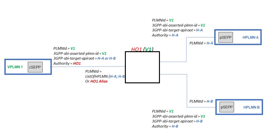
Feature Overview
The following diagram represents the overview of Hosted SEPP functionality.
Figure 3-29 Hosted SEPP Overview
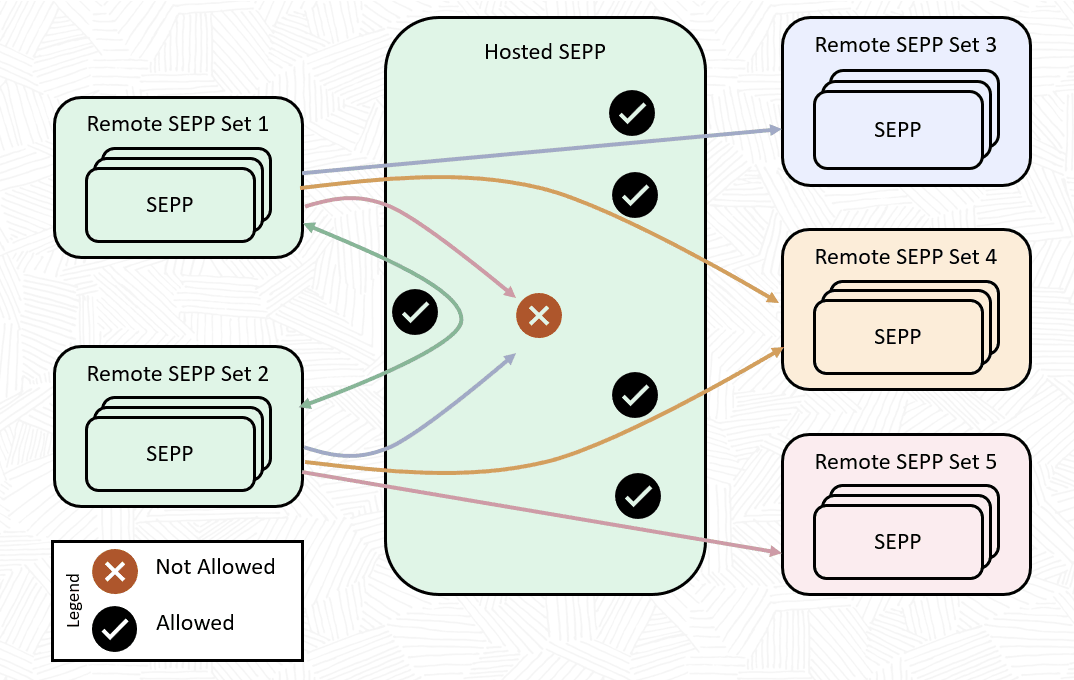
Connectivity Between Remote SEPP Sets Allowed by Hosted SEPP:
| Consumer Remote SEPP Set | Producer Remote SEPP Set | Allowed – Yes/No |
|---|---|---|
| Remote SEPP Set 1 | Remote SEPP Set 2 | YES |
| Remote SEPP Set 1 | Remote SEPP Set 3 | YES |
| Remote SEPP Set 1 | Remote SEPP Set 4 | YES |
| Remote SEPP Set 1 | Remote SEPP Set 5 | NO |
| Remote SEPP Set 2 | Remote SEPP Set 1 | YES |
| Remote SEPP Set 2 | Remote SEPP Set 3 | NO |
| Remote SEPP Set 2 | Remote SEPP Set 4 | YES |
| Remote SEPP Set 2 | Remote SEPP Set 5 | YES |
| Remote SEPP Set 3 | ANY | NO |
| Remote SEPP Set 4 | ANY | NO |
| Remote SEPP Set 5 | ANY | NO |
- Hosted SEPP can connect to multiple Remote SEPP Sets.
- Selective routing is allowed from cSEPP (Remote SEPP Set 1, Remote SEPP Set 2) to pSEPP ((Remote SEPP Set 3, Remote SEPP Set 4, and Remote SEPP Set 5).
- Hosted SEPP, while not in the physical network of the partner, or can be in the trust boundary of the partner.
- Global Error Response can be configured on the Hosted SEPP, if routing is not allowed to remote SEPP.
You can configure the Remote SEPP Set in accordance with the connectivity mentioned in the table. Each of the Remote SEPPs should have an associated Remote SEPP Set. Consumer Remote SEPP Set should be configured with the "AllowedProducerRemoteSEPPSets". This field should contain the list of the Producer Remote SEPP Sets which are allowed from the consumer. For example : PSEPP-1 Remote SEPP Set should have the list containing (PSEPP-3 and PSEPP-4) Remote SEPP Sets.
Configuration limit for Hosted SEPP:
The following table indicates the configuration limit for Hosted SEPP:
| Deployment | Max Remote PLMNs | Max PLMNs per Remote SEPP | Max Local PLMNs (Self PLMN) |
|---|---|---|---|
| Hosted SEPP | 900 | 900 | 900 |
Configuration Work flow
curl -v http://127.0.0.1:9090/sepp-configuration/v1/remoteseppset -d '{
    "name": "csepp", "primary": "remote", "allowedListName": "Default",
    "allowedProducerRemoteSeppSets" : ["psepp1,psepp2"] }' -H 'Content-Type:application/json' -X
    POST
Source Remote SEPP Set
Here, Remote SEPP Set (csepp) has two allowedProducerRemoteSeppSets "psepp1,psepp2" in the list. Therefore, Remote SEPP Set-csepp can send the traffic to the Remote SEPP Set(psepp1) and Remote SEPP Set (psepp2) only. Note that vice-versa is not applicable in this scenario. Remote SEPP Set(psepp), still cannot send the traffic to the Remote SEPP Set(csepp) if not configured.
Note:
Remote SEPP Operators (in SEPP mode) need to configure the combined (incoming and outgoing) PLMN-ID List in the remote profile while establishing TLS handshake with Hosted SEPP.In case of Hosted SEPP, consumer Remote SEPP shall be a part of a Remote SEPP Set as the selective routing is applicable between Remote SEPP Sets.
Managing Hosted SEPP Feature
Enable
You can enable the Hosted SEPP feature using the CNC Console or REST API.
Prerequisite: The parameter nrfClientEnabled must be set to false in the custom values.
- Enable using REST API: Set enabled to true in Hosted
SEPP REST API.
For more information about API path, see Oracle Communications Cloud Native Core Security Edge Protection Proxy REST Specification Guide.
'{ "hostedSepp": { "enabled": true } }' - Enable using CNC Console: In the CNC Console GUI, from the left navigation menu, navigate to SEPP and then click System Options. Select Allowed P-RSS Validation Options. Set Enable Allowed P-RSS Validation as True or False on the right pane. More details about CNC Console Configurations, see Configuring SEPP using CNC Console section.
Note:
nrfClientEnabled parameter is used to enable the Roaming Hub Mode as Hosted SEPP is applicable for Roaming Hub Mode only.Configure
You can configure the feature using REST API and CNC Console:
- Configure using REST API: Perform the feature configurations as described in the Remote SEPP Set section in Oracle Communications Cloud Native Core Security Edge Protection Proxy REST Specification Guide.
- Configure using CNC Console: Perform the feature configurations as described in Configuring SEPP using CNC Console.
- ocsepp_allowed_p_rss_routing_failure_total
- CN32F Allowed P-RSS Validation Failure Count
- PN32F Allowed P-RSS Validation Failure Count
For more information on Hosted SEPP feature related SEPP Metrics and KPIs, see SEPP Metrics and SEPP KPIs sections.
Maintain
If you encounter alerts at system or application levels, see SEPP Alerts section for resolution steps.
In case the alert still persists, perform the following steps:
- Collect the logs: For more information on how to collect logs, see Oracle Communications Cloud Native Core Security Edge Protection Proxy Troubleshooting Guide.
- Raise a service request: See My Oracle Support for more information on how to raise a service request.
3.25 Cat-0 SBI Message Schema Validation Feature
Overview
The Cat-0 SBI Message Schema Validation feature intends to support stateless security counter measures, which enhance the security measures of roaming partners by allowing only valid requests to be processed at SEPP. Cat-0 SBI Message Schema Validation feature supports the checks that are carried out to investigate if a message is valid or not.
This feature is designed to support the following:
- Validating the headers present in the SBI Message.
- Verifying the combination of request body and query parameters and compare it with the respective schema.
- Routing of only valid SBI messages to egress or ingress the network.
The Cat-0 SBI Message Schema Validation feature intends to support stateless security counter measures, which enhance roaming partners to handle security (Example: only valid requests are allowed to be processed at SEPP).
This feature is to support request validation at N32F.
As many requests traverse the SEPP, there is a security concern that a spoofing NF or an NF, which may cause not forming the messages as per specification. In such a scenario, the SEPP, which is at the boundary of the network could do a first pass for malformed or incorrect messages.
Malformed messages can be of following types:
- The JSON message may contain data that is malformed. A formatted JSON could still contain malformed data that can cause errors in the server code.
- The JSON message may contain repeated IEs or missing IEs that make the message noncompliant with its schema.
This feature intends to support message validation in the following two ways.
- Request's body value is validated against the corresponding schema as provided in 3GPP OpenAPI specifications or configured by user.
- Request's query parameters values are validated against their corresponding schema(s) as provided in 3GPP OpenAPI specifications or configured by user.
Traffic needs to be rejected or forwarded from C-SEPP or P-SEPP based on the validation results as configured by the user.
As part of the message validation feature, the following major scenarios are getting validated:
- If any SBI request JSON schema's mandatory parameter is missing, it is validated.
- If any SBI request JSON schema's mandatory parameter under an optional parameter is missing, it is validated.
- In SBI request, the regex of both the mandatory and optional parameters are validated against the regex defined in the given schema configurations.
- The data types of the IEs in SBI request are validated against the given schema configurations.
- SBI request's additional attribute is allowed or disallowed as provided in the given schema configurations.
- Any invalid JSON structure (syntax) either present in SBI request body or in request query parameters value is validated.
- Repeated IEs, either present in SBI request body or in request query parameters value, are validated.
Note:
In SEPP Mode, the Egress and Ingress requests (as per configured egress/ingress rules) are validated against the configured schema at C-SEPP and P-SEPP. In roaming hub mode, only the Ingress requests (as per configured Ingress rules) are validated.Figure 3-30 Cat-0 Functionality
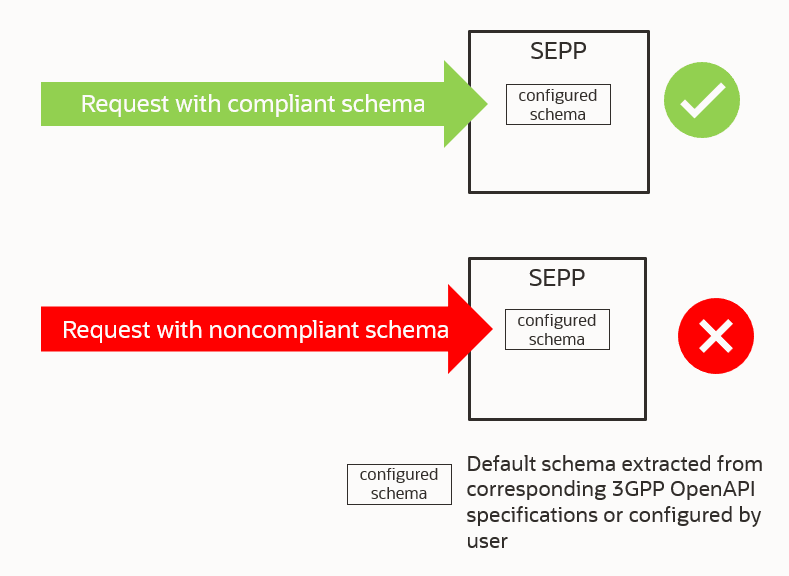
Feature Configurations
The following diagram specifies the CNC Console options available for Cat-0 SBI Message Schema Validation feature.
Figure 3-31 CNC Console options available for Cat-0 SBI Message Schema Validation feature in SEPP Mode
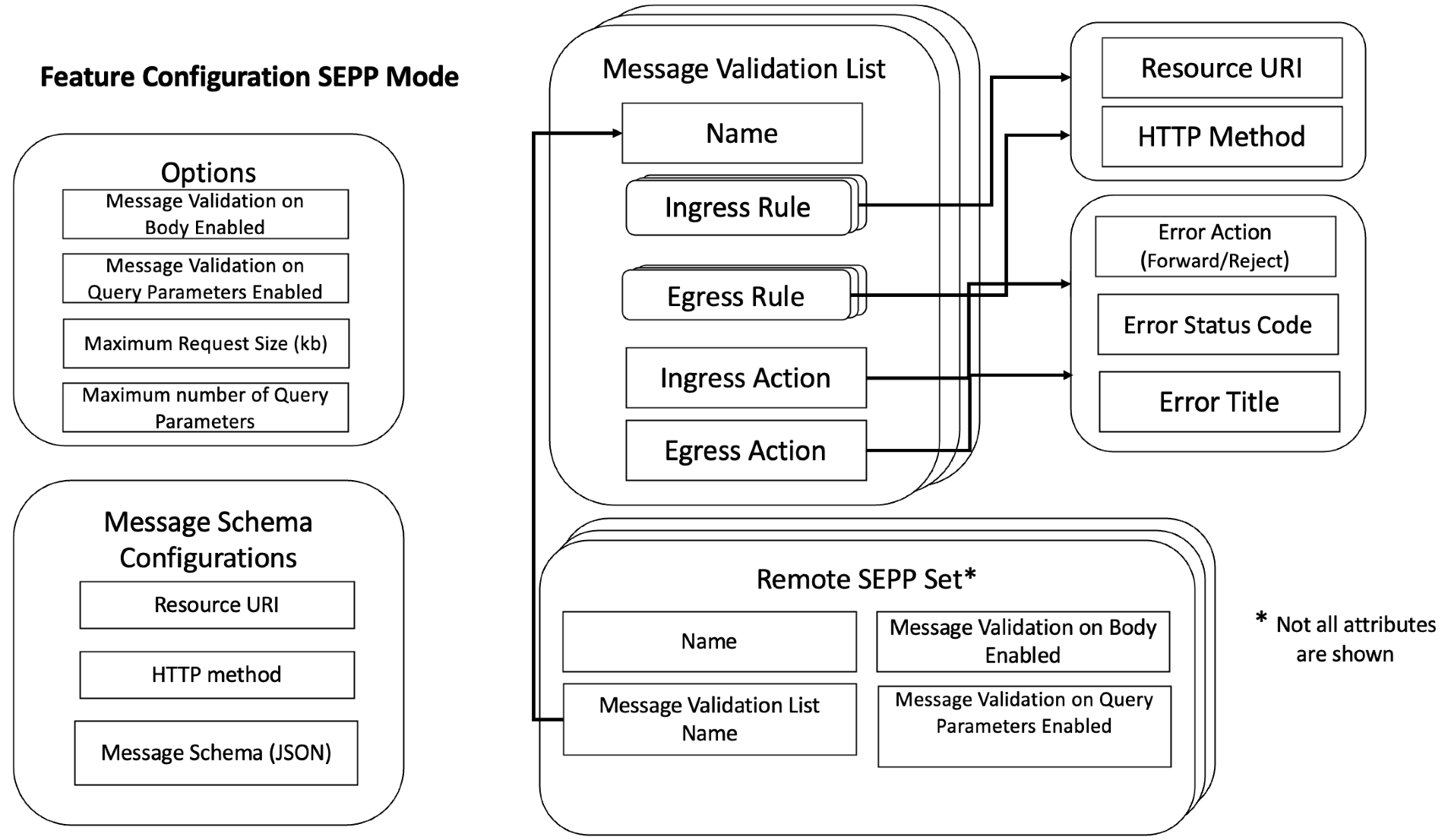
Figure 3-32 CNC Console options available for Cat - 0 SBI Message Schema Validation feature in Roaming Hub Mode
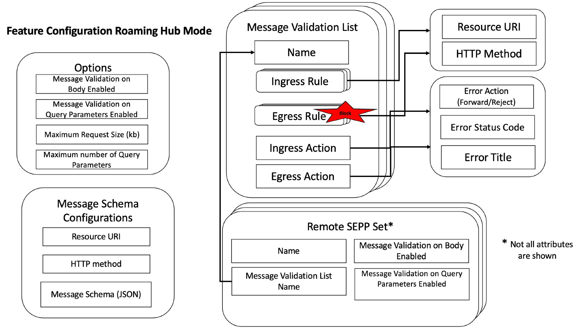
The following section explains the configurations in detail:
Options
Message Validation on Body Enabledenables or disables the feature on request body.Message Validation on Query Parameters Enabledenables or disables the feature on request query parameters.Maximum Request Size(kb)provides the maximum allowed request body size (Default is 40 KB)Maximum Number Of Query Parametersprovides the maximum number of allowed query parameters (Default is 100).
Message Validation List
- As part of this feature configuration, multiple Message Validation Lists can be configured.
- Default Message Validation List with the name Default is configured during SEPP installation which can used as a sample to visualize the rules.
- Default list uses exhaustive number of rules, and its usage impacts the performance.
- Ingress and Egress Rules define the SBI requests to be validated.
- SEPP in Roaming Hub mode supports Ingress Rules only.
- Ingress and Egress Action defines the Action (Forward or Reject), Status Code, and Title to be used in case message validation gets failed for C-SEPP or P-SEPP.
- Any one of the existing Message Validation Lists can be configured for a Remote SEPP Set. By default, the default Message Validation List is configured and the feature is disabled.
Message Validation Configuration in Remote SEPP Set
The user needs to associate the required message validation list to the Remote SEPP Set for which the feature has to be applied.
Note:
To enable the feature, the user needs to enable theMessage Validation on Body Enabled and
Message Validation on Query Parameters Enabled options
available at Option screen and Remote SEPP Set CNC Console screens or REST
APIs.
Message Schema Configurations
For the supported resource URI and HTTP methods, SEPP provides the default JSON schemas (application or json) that are used to do the message schema validation. The user can do any changes in the default schema or delete it using CNC Console or REST APIs. Before overwriting the default schema, creating a backup of existing schema is advisable, as once overwritten, SEPP will not provide the default schema. User provided custom schema should be fully resolved, that is, it should not have any internal references to other schemas.
To add a new resource URI, HTTP method and corresponding schema, resource URI, and HTTP method need to be present in SEPP's default service APIs.
Sample Request Body Schema
Request body schema must be provided in the valid JSON format.
{
  "required" : [ "amfStatusUri" ],
  "type" : "object",
  "properties" : {
    "amfStatusUri" : {
      "type" : "string"
    },
    "guamiList" : {
      "minItems" : 1,
      "type" : "array",
      "items" : {
        "required" : [ "amfId", "plmnId" ],
        "type" : "object",
        "properties" : {
          "plmnId" : {
            "required" : [ "mcc", "mnc" ],
            "type" : "object",
            "properties" : {
              "mcc" : {
                "pattern" : "^\\d{3}$",
                "type" : "string"
              },
              "mnc" : {
                "pattern" : "^\\d{2,3}$",
                "type" : "string"
              },
              "nid" : {
                "pattern" : "^[A-Fa-f0-9]{11}$",
                "type" : "string"
              }
            }
          },
          "amfId" : {
            "pattern" : "^[A-Fa-f0-9]{6}$",
            "type" : "string"
          }
        }
      }
    }
  }
}Query parameter and corresponding schema should be provided in the form of JSON array where each array element will provide information for one query parameter. This information must have the following mandatory attributes:
name: name of the query parameter as used in the request URI.
in: type of parameter, it should be 'query' to indicate that its is a query parameter, any other type will not be supported.
required: true/false, provides mandatory or optional parameter information.
schema or content (application/json): json schema for the parameter.
The following example shows the schemas (JSON array format) of two query parameters (supported-features and plmn-id):
[ {
  "name" : "supported-features",
  "in" : "query",
  "required" : false,
  "schema" : {
    "pattern" : "^[A-Fa-f0-9]*$",
    "type" : "string"
  }
}, {
  "name" : "plmn-id",
  "in" : "query",
  "required" : false,
  "content" : {
    "application/json" : {
      "schema" : {
        "required" : [ "mcc", "mnc" ],
        "type" : "object",
        "properties" : {
          "mcc" : {
            "pattern" : "^\\d{3}$",
            "type" : "string"
          },
          "mnc" : {
            "pattern" : "^\\d{2,3}$",
            "type" : "string"
          }
        }
      }
    }
  }
} ]
Managing Cat-0 SBI Message Schema Validation Feature
You can enable the Cat-0 SBI Message Schema Validation feature using the CNC Console or REST API.
Enable using REST API
Set MessageValidationOnBodyEnabled and
MessageValidationOnQueryParametersEnabled to true in Message
Validation REST API.
curl -X 'PUT' \
  'http://<SEPP- Configuration IP>:<PORT>/sepp-configuration/v1/security-counter-measure/message-validation/options' \
  -H 'accept: */*' \
  -H 'Content-Type: application/json' \
  -d '{
  "messageValidationOption": {
    "messageValidationOnBodyEnabled": true,
    "messageValidationOnQueryParametersEnabled": true,
    "maxRequestSize": 0,
    "maxNumberOfQueryParams": 0
  }
}'
For more information about API path, see Oracle Communications Cloud Native Core, Security Edge Protection Proxy REST Specification Guide.
Enable using CNC Console
- From the left navigation menu, navigate to SEPP and then click Security Countermeasure.
- Click Cat 0 - SBI Message Validation under Security Countermeasure. The Option appears underneath.
- Click Option, the option screen appears at the right pane. The Cat 0 - SBI Message Validation feature details are available in the screen.
- Click Edit icon to modify the Option. The Edit Option page appears.
- Set the Message Validation on Body Enabled and Message Validation on Query Parameters Enabled to True.
For more details about CNC Console configurations, see Configuring SEPP using CNC Console section in the Oracle Communications Cloud Native Core, Security Edge Protection Proxy User Guide.
Note:
To enable the feature, the user also needs to enable theMessage
Validation on Body Enabled and Message Validation on Query
Parameters Enabled options available at Remote SEPP Set, using CNC
Console screen or REST APIs.
- ocsepp_message_validation_applied_total
- ocsepp_message_validation_on_body_failure_total
- ocsepp_message_validation_on_header_failure_total
- Message validation applied requests on cn32f
- Cn32f message validation failure on request body
- Cn32f message validation failures on request query parameter(s)
- Message validation applied requests on pn32f
- Pn32f message validation failure on request body
- Pn32f message validation failures on request query parameter(s)
For more information on Cat-0 SBI Message Schema Validation feature related SEPP Metrics and KPIs, see SEPP Metrics and SEPP KPIs sections.
Maintain
If you encounter alerts at system or application levels, see SEPP Alerts section for resolution steps.
In case the alert still persists, perform the following:
- Collect the logs: For more information on how to collect logs, see Oracle Communications Cloud Native Core, Security Edge Protection Proxy Troubleshooting Guide.
- Raise a service request: See My Oracle Support for more information on how to raise a service request.
3.26 Cat 2 - Network ID Validation Feature
Cat 2 - Network ID Validation feature refers to the checks carried out to investigate if a message is sent from home or the allocated network (for example, in case of a shared infrastructure). This feature also determines if there are any inconsistencies between the information in the lower level and in the embedded packets and IEs.
An example of this is the MCC/MNC combination in the incoming SUPI/SUCI that
could be validated against Home PLMN IDs that are supported by the P-SEPP. Also, any
message configured to validate CSEPP PLMN ID, that contains the
servingNetworkName Body IE parameter could be validated against
Visited network PLMN ID supported by C-SEPP.
Cat 2 – Network ID Validation feature allows the user to validate the PLMN ID of Producer SEPP and Consumer SEPP in the SBI Request Messages over N32 Interface in SEPP Mode as well as in Roaming Hub Mode.
This feature is not applicable to SBI responses that is, only SBI requests are validated.
Design and Architecture
The following diagram represents the Cat 2 – Network ID validation feature in SEPP mode.
SEPP Mode
Figure 3-33 SEPP Mode
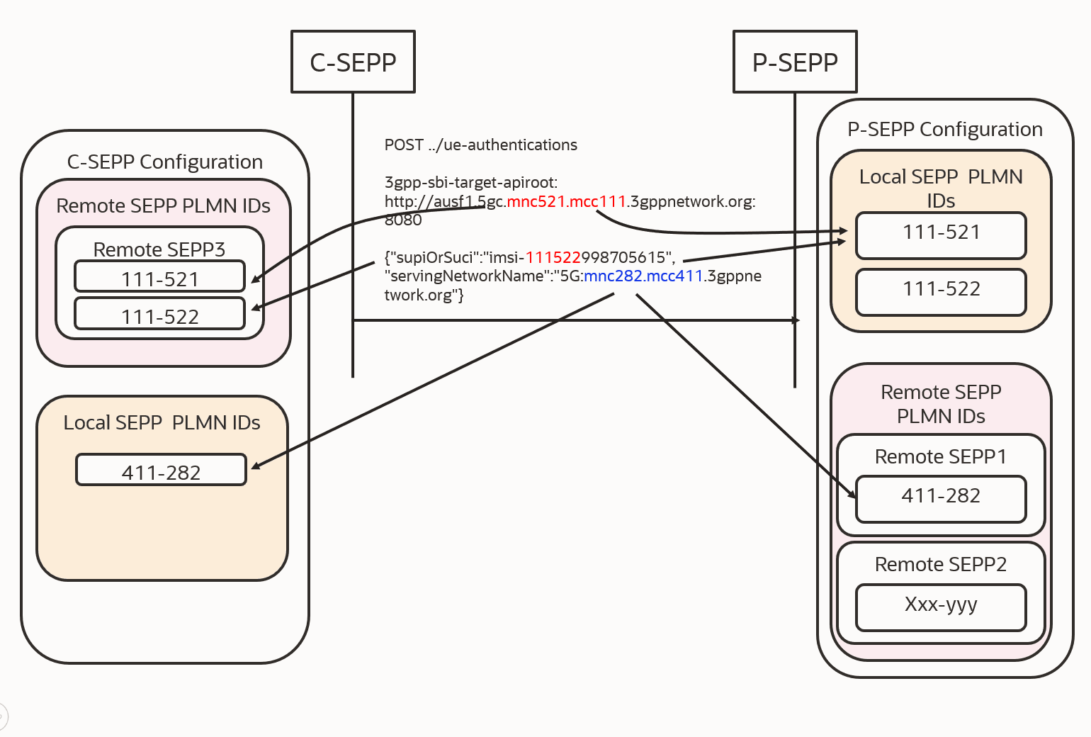
In SEPP Mode, this feature can be applied on Producer SEPP (P-SEPP) as well as on Consumer SEPP (C-SEPP). At Producer SEPP, this feature validates the P-SEPP PLMN ID against the configured Local SEPP PLMN IDs in the N32 Ingress SBI requests (header and JSON IE) and C-SEPP PLMN ID against the configured Remote SEPP PLMN IDs.
Where as, at Consumer SEPP, this feature validates the P-SEPP PLMN ID against the configured Producer Remote SEPP PLMN IDs in the N32 Egress SBI requests (header and JSON IE) and C-SEPP PLMN ID against Local SEPP PLMN IDs configured at C-SEPP.
When the feature is enabled at C-SEPP:
- If the user wants to validate the PLMN ID in 3gpp-sbi-target-apiroot header, then user can add a configuration for this header in Header Configuration for ALL Service APIs or for a particular Service API. Once the configuration is done, and if it is configured for ALL Service APIs, then for every SBI request message containing 3gpp-sbi-target-apiroot header, PLMN ID is extracted from MCC and MNC part of this header and is compared with the Remote SEPP PLMN IDs. If a match is found, then that request is allowed and if a match is not found, then that request is rejected or forwarded as per user configured Error Configuration.
- If user wants to validate supiOrSuci value in UE Authentication SBI request message, then user can add a configuration for this JSON IE in Body Configuration for UE Authentication SBI request API. Once the configuration is done, then for every UE Authentication SBI request message, PLMN ID is extracted from supiOrSuci IE and is compared with the Remote SEPP PLMN IDs. If a match is found, then that request is allowed and if a match is not found then that request is rejected or forwarded as per user configured Error Configuration.
- If user wants to validate servingNetworkName value in UE Authentication SBI request message, then user can add a configuration for this JSON IE in Body Configuration for UE Authentication SBI request API. Once the configuration is done, then for every UE Authentication SBI request message, PLMN ID is extracted from servingNetworkName IE and is compared with the Local SEPP PLMN IDs. If a match is found, then that request is allowed and if a match is not found, then that request is rejected or forwarded as per user configured Error Configuration.
When the feature is enabled at P-SEPP:
- If the user wants to validate the PLMN ID in 3gpp-sbi-target-apiroot header, then user can add a configuration for this header in Header Configuration for all Service APIs or for a particular Service API. Once the configuration is done, and if it is configured for all Service APIs, then for every SBI request Message containing 3gpp-sbi-target-apiroot header, PLMN ID is extracted from MCC and MNC part of this header and is compared with the Local SEPP PLMN IDs. If a match is found, then that request is allowed and if a match is not found, then that request is rejected or forwarded as per user configured Error Configuration.
- If the user wants to validate supiOrSuci value in UE Authentication SBI request message, then the user can add a configuration for this JSON IE in Body Configuration for UE Authentication SBI request API. Once the configuration is done, then for every UE Authentication SBI request message, PLMN ID is extracted from supiOrSuci IE and is compared with the Local SEPP PLMN IDs. If a match is found, then that request is allowed and if a match is not found, then that request is rejected or forwarded as per user configured Error Configuration.
- If the user wants to validate servingNetworkName value in UE Authentication SBI request message, then user can add a configuration for this JSON IE in Body Configuration for UE Authentication SBI request API. Once the configuration is done, then for every UE Authentication SBI request message, PLMN ID is extracted fromservingNetworkName IE and is compared with the Remote SEPP PLMN IDs. If a match is found, then that request is allowed and if a match is not found then that request is rejected or forwarded as per user configured Error configuration.
In Roaming Hub mode
Figure 3-34 Roaming Hub mode
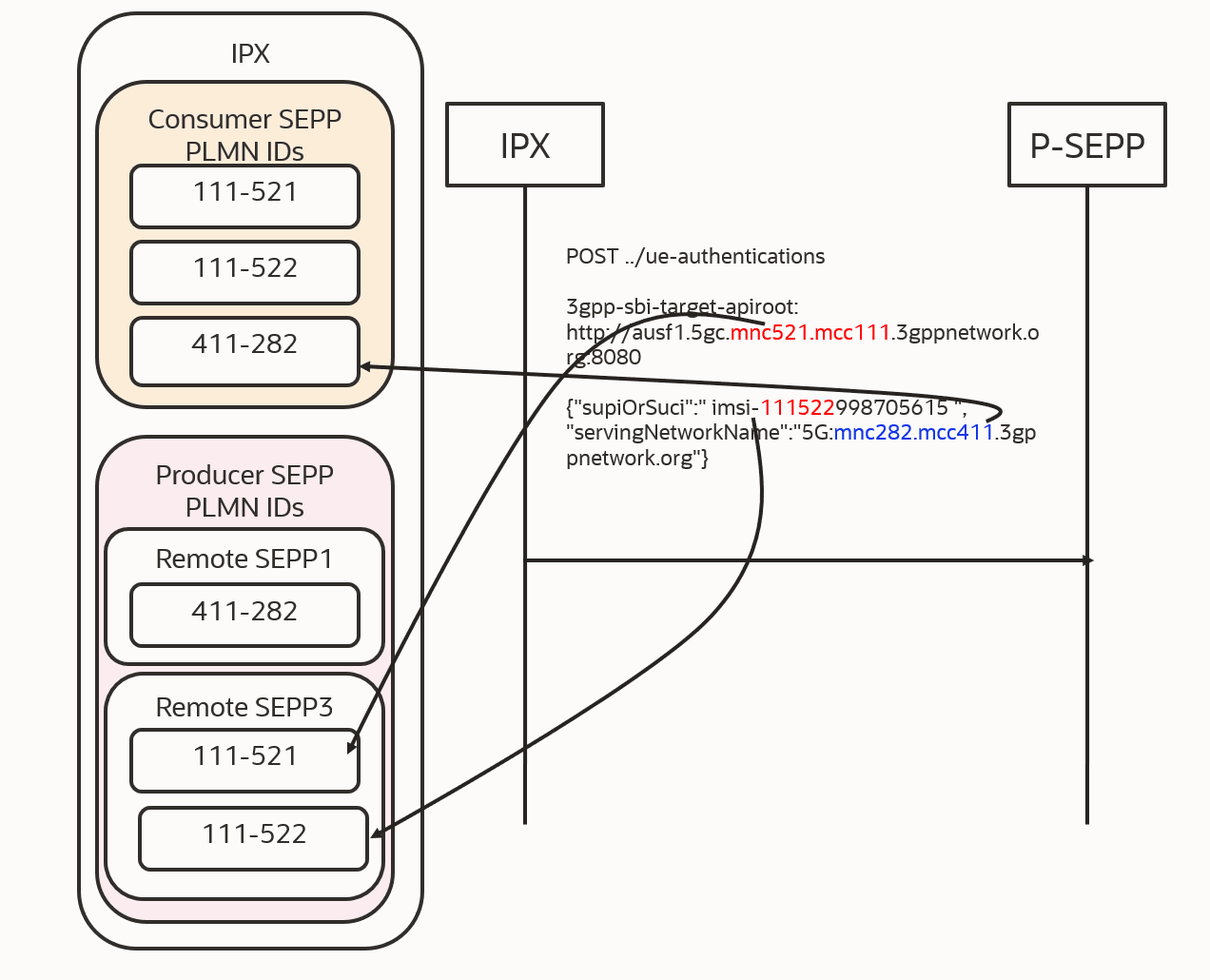
In Roaming Hub mode, this feature validates the P-SEPP PLMN ID (received in the incoming message in 3gpp-sbi-target-apiroot and supiOrSuci) against the configured Producer Remote SEPP PLMN IDs in the N32 Egress SBI requests (header and JSON IE) and C-SEPP PLMN ID against the Consumer Remote SEPP PLMN IDs. In this mode, only Egress SBI requests are validated. Ingress SBI requests are not validated. So, user is not allowed to add Ingress Rules in Network ID Validation List of the feature.
When the feature is enabled at Roaming Hub:
- If the user wants to validate the PLMN ID in 3gpp-sbi-target-apiroot header, then user can add a configuration for this header in Header Configuration for all Service APIs or for a particular Service API. Once the configuration is done, and if it is configured for all Service APIs then for every SBI request Message containing 3gpp-sbi-target-apiroot header, PLMN ID is extracted from MCC and MNC part of this header and is compared with the Producer SEPP PLMN IDs. If a match is found, then that request is allowed and if a match is not found then that request is rejected or forwarded as per user configured Error Configuration.
- If the user wants to validate supiOrSuci value in UE Authentication SBI request message, then user can add a configuration for this JSON IE in Body Configuration for UE Authentication SBI request API. Once the configuration is done, then for every UE Authentication SBI request message, PLMN ID is extracted from supiOrSuci IE and is compared with the Producer SEPP PLMN IDs. If a match is found, then that request is allowed and if a match is not found then that request is rejected or forwarded as per user configured Error Configuration.
- If user wants to validate servingNetworkName value in UE Authentication SBI request message, then user can add a configuration for this JSON IE in Body Configuration for UE Authentication SBI request API. Once the configuration is done, then for every UE Authentication SBI request message, PLMN ID is extracted fromservingNetworkName IE and is compared with the Consumer SEPP PLMN IDs. If a match is found, then that request is allowed and if a match is not found then that request is rejected or forwarded as per user configured Error Configuration.
Configurations
The following diagram specifies the CNC Console options available for Cat 2 – Network ID Validation.
Figure 3-35 CNC Console options available for Cat 2 – Network ID Validation
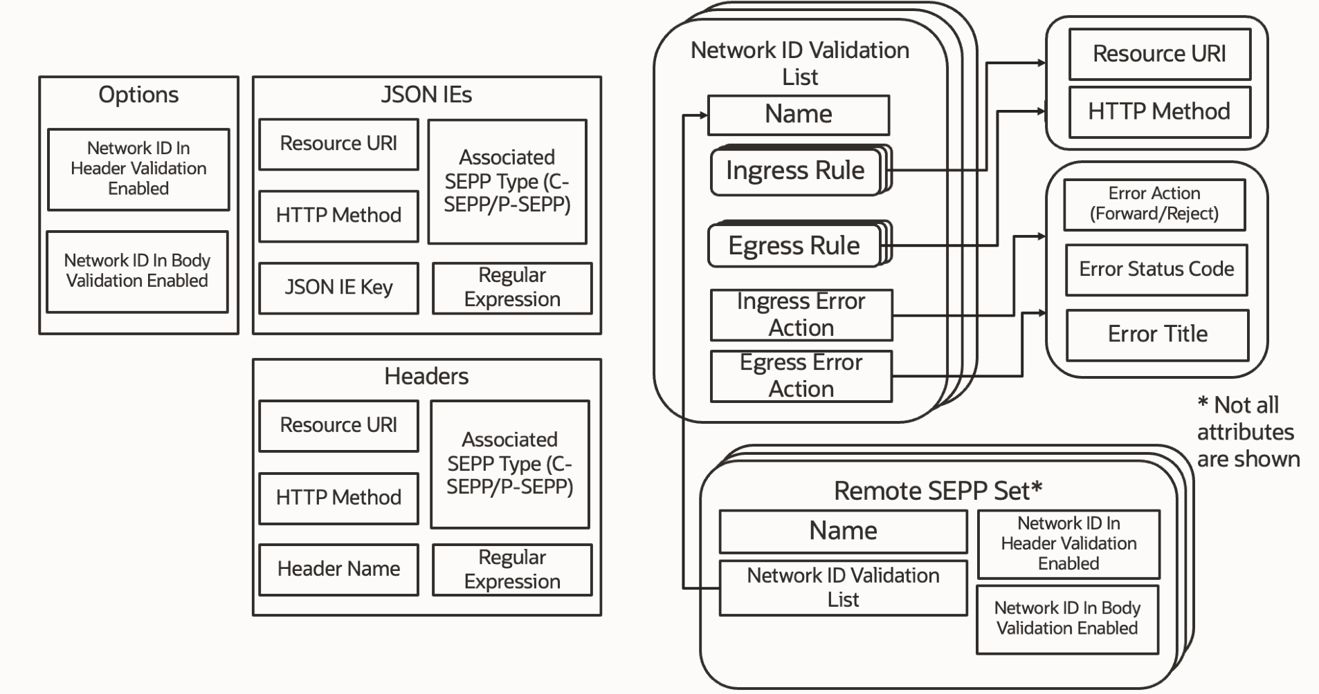
The list of options available in CNC Console is as follows:
- Options
- JSON IEs
- Headers
- Network ID Validation List
- Remote SEPP Set
Feature Configuration –Network ID Validation List
Figure 3-36 Feature Configuration – Network ID Validation List
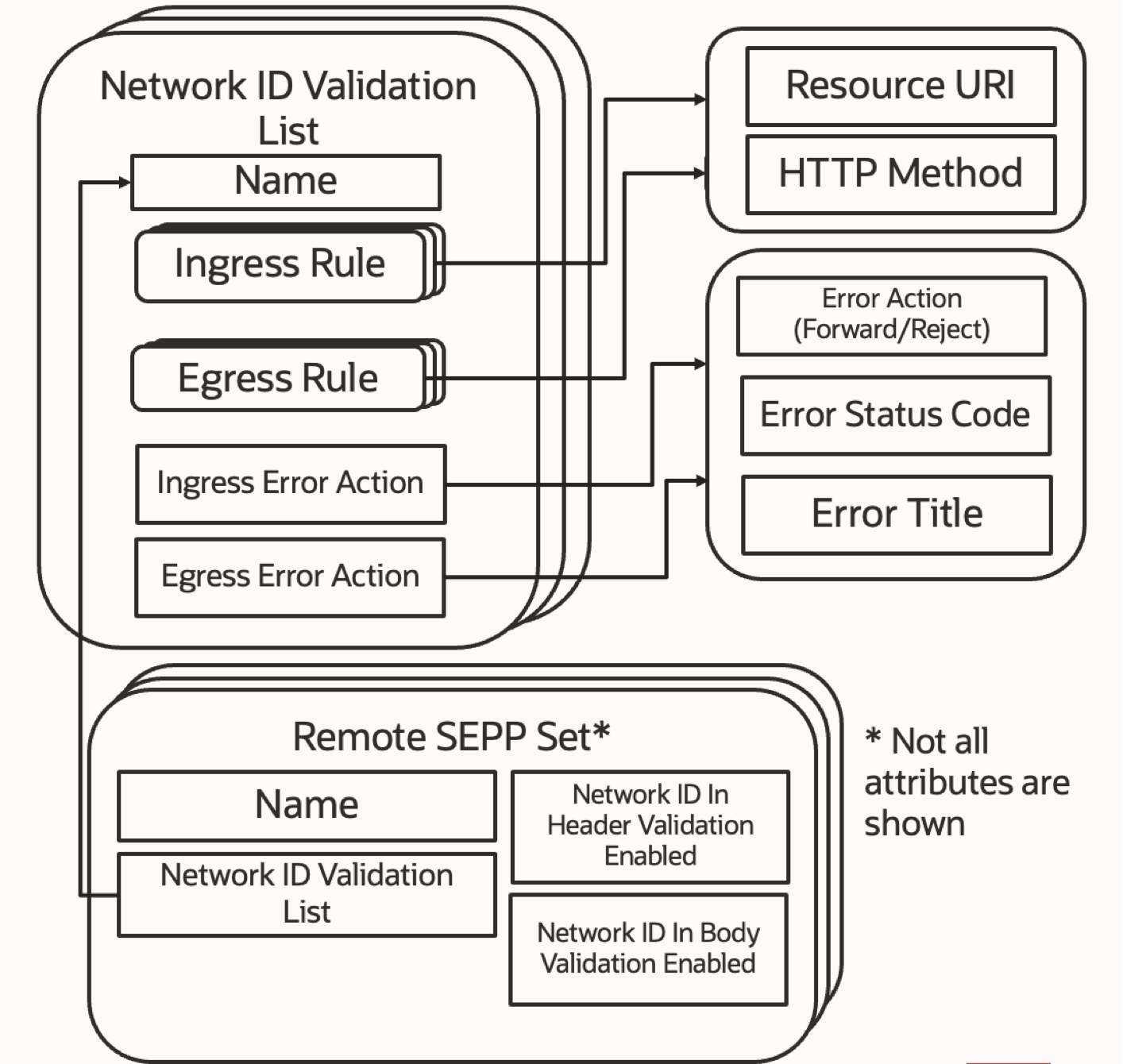
- As part of this feature configuration, multiple Network ID Validation Lists can be configured for a Remote SEPP Set.
- Default Network ID Validation List with the name Default is configured during SEPP installation which can used as a sample to visualize the rules.
- Default list uses exhaustive number of rules, and it is usage impacts the performance.
- A Network ID Validation List is configured for a Remote SEPP Set if the feature is enabled.
- By default, the feature is disabled and the default Network ID Validation List is configured.
- Ingress and Egress Rules define the SBI requests to be validated.
- SEPP in Roaming Hub mode supports Egress Rules only.
- Ingress and Egress Action defines the Action (Forward/Reject), Status Code, and Title to be used in case SEPP fails to validate the SBI request for the C-SEPP or P-SEPP PLMN ID.
Feature Configuration –Options,Headers, JSON IEs
- Options Configuration
- Allows feature to be enabled for validating Network ID in Header or Body.
- Headers Configuration
- SBI request is identified by Resource URI and HTTP Method.
- Header is identified by name.
- Regular Expression extracts the PLMN from the header value.
- JSON IEs Configuration
- SBI request is identified by Resource URI and HTTP Method.
- JSON Body IE key is identified by name.
- Regular Expression extracts the PLMN from the IE value.
Note:
If JSON IE name is present in the root path of the JSON as well as present in the nested object, then it is recommended to keep the JSON IE which is present in the root if we want to validate it. If the child JSON IE has to be validating, it is recommended to configure it is own parent JSON IE.Example:
{"plmnId": {
          "mcc": "111",
          "mnc": "111"
        }
"ueLocation": {
    "eutraLocation": {
      "tai": {
        "plmnId": {
          "mcc": "111",
          "mnc": "111"
        },
        "tac": "string",
        "nid": "string"
      }}}}
In the above example, if a user wants to validate
plmnId which is present inside taiobject,
then the user has to give identifier name as tai in Body IE
Configuration. If the user has configured plmnId in Body IE
Configuration, then as per this example, the toplevel plmnId
gets validated.
Note:
- In C-SEPP and P-SEPP, by default, the three digit mnc is supported for identifiers that have associated SEPP type configured as C-SEPP and P-SEPP in Header and Body table configurations.
- If the user wants to support two digit mnc, then the user can configure the regex in Header and Body table configurations for that identifier. The two digit mnc configuration will be applicable for all the Remote SEPP Sets.
Managing Cat 2 - Network ID Validation Feature
Enable
You can enable the Cat 2 - Network ID Validation feature using the CNC Console or REST API.
- Enable using REST API: Set
messageFilteringOnPlmnHeaderValidation and
messageFilteringOnPlmnBodyValidation to true in Security Counter
Measure REST API.
For more information about API path, see Oracle Communications Cloud Native Core, Security Edge Protection Proxy REST Specification Guide.
curl -X 'PUT' \ 'http://<SEPP- Configuration IP>:<PORT>/sepp-configuration/v1/security-counter-measure/network-id-validation/options' \ -H 'accept: */*' \ -H 'Content-Type: application/json' \ -d '{ "networkIdValidationEnabled": { "messageFilteringOnNetworkIdHeaderValidation": true, "messageFilteringOnNetworkIdBodyValidation": true } }' - Enable using CNC Console:
- In the CNC Console GUI, from the left navigation menu, navigate to SEPP and then click Security Countermeasure.
- Select Cat 2 – Network ID Validation.
- The Option appears underneath.
- Click Option, the option screen appears at the right pane. The Cat 2 – Network ID Validation Feature details are available in the screen.
- Click Edit icon to modify the Option. The Edit Option page appears.
- Set Network ID in Header Validation Enabled and Network ID in Body Validation Enabled to True or False on the right pane.
Configure
You can configure the feature using REST API and CNC Console:
- Configure using REST API: Perform the feature configurations as described in Cat 2–Network ID Validation System Option section in Oracle Communications Cloud Native Core, Security Edge Protection Proxy REST Specification Guide.
- Configure using CNC Console: Perform the feature configurations as described in Configuring SEPP using CNC Console.
- ocsepp_network_id_validation_header_failure_total
- ocsepp_network_id_validation_body_failure_total
For more information on CAT 2- Network ID Validation feature related SEPP Metrics and KPIs, see SEPP Metrics and SEPP KPIs sections.
Maintain
If you encounter alerts at system or application levels, see SEPP Alerts section for resolution steps.
In case the alert still persists, perform the following steps:
- Collect the logs: For more information on how to collect logs, see Oracle Communications Cloud Native Core, Security Edge Protection Proxy Troubleshooting Guide.
- Raise a service request: See My Oracle Support for more information on how to raise a service request.
3.27 Cat-3 Previous Location Check Feature
Cat-3 Previous Location Check feature is a part of stateful security countermeasures. This feature verifies that only those messages are allowed to traverse the network, which are from an authenticated UE and from the same location from where the UE got authenticated previously.
The authentication status is retrieved from the UDR in the home network for a particular User Equipment (UE) and the same is verified for every incoming message reaching the Producer SEPP (P-SEPP). When the UE is verified from the UDR response, that message is allowed to pass through P-SEPP. If the UE is not authenticated or the location of the incoming message do not match with the location registered in UDR at the time of UE authentication process, the message is rejected and displays the user configurable error response.
Note:
This feature is available only on P-SEPP.Design and Architecture
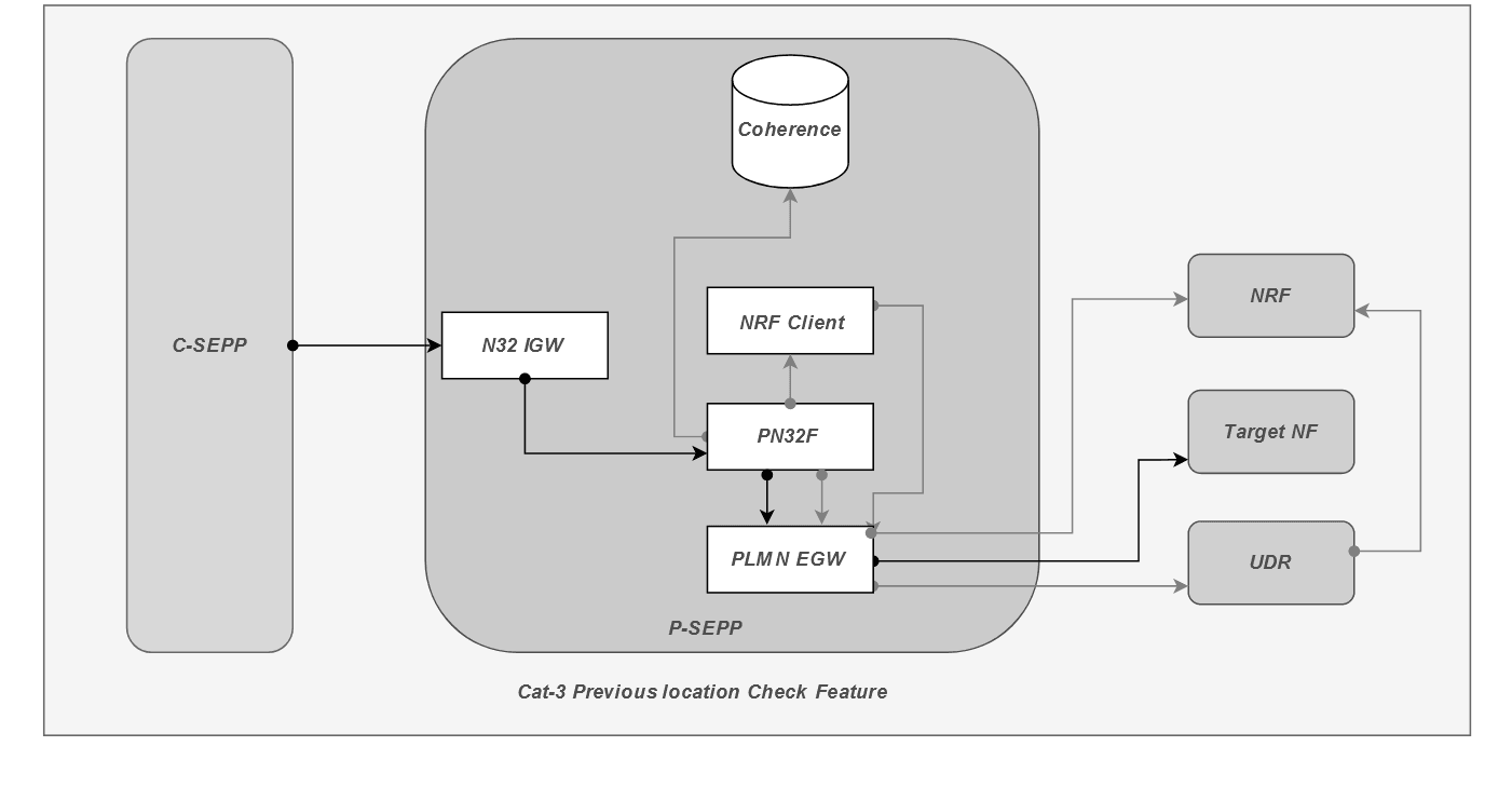
The diagram shows the functionality of Cat-3 Previous Location Check feature.
At the INIT time of SEPP, or when the SEPP is up and running, PN32F microservice sends a trigger to nrf-client microservice to discover the UDR profile registered with the NRF of home network (P-SEPP) through the PLMN Egress Gateway. The UDR registers its profile with NRF where SEPP is in the allowedNFtype list. Once the UDR profile is received by nrf-client, PN32F microservice stores the details (UDR profile details like FQDN, SUPI range, Port Number, Scheme (HTTP or HTTPS) so on) in coherence cache.
Whenever an incoming Ingress request message reaches P-SEPP, the PN32F microservice fetches the UE ID and the serving network ID from the Ingress request (from the Header or Body JSON) and searches for the UDR FQDN in UDR profile received in the UDR Discovery response. Once UDR FQDN is found in coherence cache map, PN32F microservice sends a request to UDR through PLMN Egress Gateway for finding the authentication status of the UE ID received in the ingress request message. UDR responds with the authentication status of the UE along with the previously authenticated location. PN32F now checks for the authentication status received from UDR. If the UE is authenticated, it then matches the serving network PLMN received in the Ingress request message along with the PLMN in Serving Network Name received in UE authentication message response. If both match, then the request is forwarded to the target NF.
Managing Cat-3 Previous Location Check Feature
You can enable the Cat-3 Previous Location Check feature using the Helm parameters, CNC Console, or REST API.
Enable using Helm Parameter
Set the seppCoherenceServiceEnabled parameter to
true in the N32 Ingress Gateway section of
ocsepp_custom_values_<version>.yaml file.
seppCoherenceServiceEnabled: trueFor more information about the Helm parameters, see Oracle Communications Cloud Native Core, Security Edge Protection Proxy Installation, Upgrade, and Fault Recovery Guide.
Enable using REST API
Set messageFilteringOnPreviousLocationCheckValidation to
true in Previous Location Check REST API.
curl -X 'PUT' \
  'http://<SEPP- Configuration IP>:<PORT>/sepp-configuration/v1/security-counter-measure/previous-location-validation/options' \
  -H 'accept: */*' \
  -H 'Content-Type: application/json' \
  -d '{
  "previousLocationCheckValidationEnabled": {
    "cacheRefreshTimer": 5000,
    "messageFilteringOnPreviousLocationCheckValidation": false
  }
}'
For more information about API path, see Oracle Communications Cloud Native Core, Security Edge Protection Proxy REST Specification Guide.
Enable using CNC Console
- From the left navigation menu, navigate to SEPP and then click Security Countermeasure.
- Click Cat 3 - Previous Location Check under Security Countermeasure. The Option appears underneath.
- Click Option, the option screen appears at the right pane. The Cat 3 - Previous Location Check feature details are available on the screen.
- Click Edit icon to modify the Option. The Edit Option page appears.
- Set the Previous Location Check Enabled to True.
For more details about CNC Console configurations, see Configuring SEPP using CNC Console.
- ocsepp_previous_location_exception_failure_total
- ocsepp_previous_location_validation_success_total
- ocsepp_previous_location_validation_failure_total
- ocsepp_previous_location_validation_requests_total
For more information on Cat-3 Previous Location Check feature related SEPP Metrics and KPIs, see SEPP Metrics and SEPP KPIs sections.
Maintain
If you encounter alerts at system or application levels, see SEPP Alerts section for resolution steps.
In case the alert still persists, perform the following:
- Collect the logs: For more information on how to collect logs, see Oracle Communications Cloud Native Core, Security Edge Protection Proxy Troubleshooting Guide.
- Raise a service request: See My Oracle Support for more information on how to raise a service request.
3.28 Steering of Roaming (SOR) feature
SOR is deployed as a roaming management solution intended for optimizing roaming cooperation between operators. It allows flexible network selection management for outbound roamers to stimulate an appropriate roaming network choice for subscribers.
SEPP supports the SOR feature to provide better roaming experience to the customers. With this feature, instead of connecting to the required NF, SEPP sends the request to SOR. SOR either connects to the required subscriber or returns the location of the required subscriber to the home SEPP.
The following diagram represents the overview of SOR functionality.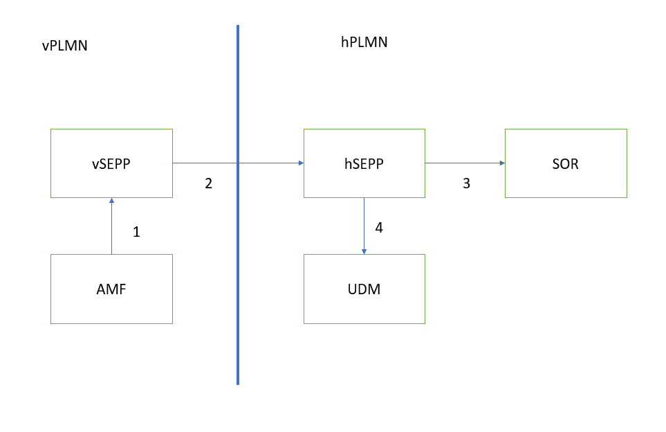
- AMF initiates request towards vSEPP for roaming subscriber.
- vSEPP forwards the request towards the hSEPP.
- Hsepp checks method type and RURI (request URI) and if it matches, then forwards the request to the SOR platform.
- Based on the response, hSEPP forwards the request to the UDM.
The SOR platform receives the standard SBI messages as the input to decide the redirection. The SOR platform responds with a standard HTTP/2 defined response code for redirection.
The SOR platform can either send a response to the SEPP or can directly forward the request to the required UDM. The customer can choose one of the two modes.
- Redirection Disabled Mode (Passive Mode)
- Redirection Enabled Mode (Active Mode)
Redirection Disabled Mode
Figure 3-37 Redirection Disabled Mode
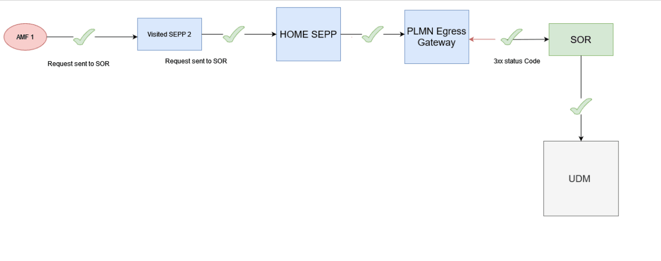
Here, SOR platform is acting as a front end. Hence, the search time is less and the SOR platform does the load balance.
Redirection Enabled Mode
In this mode, SOR returns the location of the required subscriber to the home SEPP. In this mode, the producer SEPP receives the 3xx redirection http status code. If it matches the redirection code configured at CNC Console or REST API, then producer SEPP reads the location header and connects to the producer NF. In this mode, configuring SOR is easier.
Figure 3-38 Redirection Enabled Mode
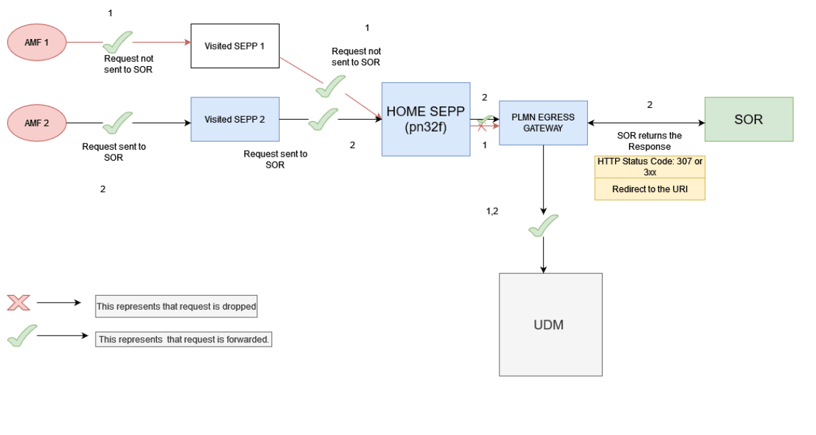
Managing Steering of Roaming (SOR) Feature
Enable
You can enable the SOR feature using the CNC Console or REST API.
Enable using REST API
enabled to true in SOR REST API.
{
  "enabled": true,
  "retryToProducer": true,
  "redirection": {
    "enabled": true,
    "codes": "308"
  },
  "servers": [
    {
      "priority": "PRIMARY",
      "httpScheme": "http",
      "sorFqdn": "service-nodejs-2-mnc100-mcc111-3gppnetwork-org.adity-sepp2",
      "sorPort": "7070",
      "apiPrefix": "sor",
      "serverHeader": "SOR-service-nodejs-2-mnc100-mcc111-3gppnetwork-org.adity-sepp2"
    }
  ],
  "retryWait": {
    "retryAltSor": false,
    "retryTime": 1000,
    "retryCount": 0
  },
  "httpCodes": {
    "errorCodes": "501",
    "exceptions": "java.util.concurrent.TimeoutException"
  },
  "errorConfiguration": {
    "errorCodesToConsumer": "408",
    "errorMessageToConsumer": "Timeout at SOR"
  }
}Enable using CNC Console
- In the CNC Console GUI, from the left navigation menu, navigate to SEPP and then click SOR.
- The Option appears underneath.
- Click Option, the option screen appears at the right pane. The SOR Feature details are available in the screen.
- Click Edit icon to modify the Option. The Edit Option page appears.
- Set SOR Enabled to True on the right pane.
More details about CNC Console Configurations, see Configuring SEPP using CNC Console section.
Configure
You can configure the feature using REST API and CNC Console.
- Configure using REST API: Perform the feature configurations as described in SOR and SOR Config Allowed List REST APIs in Oracle Communications Cloud Native Core, Security Edge Protection Proxy REST Specification Guide.
- Configure using CNC Console: Perform the feature configurations as described in Configuring SEPP using CNC Console.
Observe
Following are the SOR feature specific metrics:
- ocsepp_pn32f_sor_requests_total
- ocsepp_pn32f_sor_responses_total
- ocsepp_pn32f_sor_retry_to_producer_requests_total
- ocsepp_pn32f_sor_back_to_consumer_responses_total
- ocsepp_pn32f_sor_failure_total
- ocsepp_pn32f_sor_timeout_failure_total
Following are the SOR feature specific KPIs:
- Pn32f to SoR Request count total
- SoR to Pn32f Response count total
For more information about metrics and KPIs, see SEPP Metrics and SEPP KPIs sections.
Maintain
If you encounter alerts at system or application levels, see SEPP Alerts section for resolution steps.
In case the alert still persists, perform the following:
- Collect the logs and Troubleshooting Scenarios: For more information on how to collect logs and troubleshooting information, see Oracle Communications Cloud Native Core, Security Edge Protection Proxy Troubleshooting Guide.
- Raise a service request: See My Oracle Support for more information on how to raise a service request.
3.29 Rate Limiting for Ingress Roaming Signaling per Remote SEPP Set
Overview
This feature provides ingress request rate limiting on N32 Interface based on Remote SEPP Set to throttle messages from the Remote SEPP sending more than configured limit for the Remote SEPP Set.
There can be scenarios where the flood of messages at Remote SEPP Set level need to be controlled. With this feature, SEPP secures the network when aggregated traffic at the Remote SEPP level exceeds the allowed traffic rate limit.
If the traffic exceeds the allowed traffic rate limit, SEPP does not process the traffic and responds with an error code. The rate limiting functionality at the SEPP allows an operator to configure the acceptable traffic rate from a consumer NF instance.
SEPP enables users to configure the maximum number of incoming messages at a given duration.
Algorithm
The Rate Limiting for Ingress Roaming Signaling per Remote SEPP Set feature is implemented using customised Bucket4j which uses TokenBucket Algorithm.
The following is the token bucket algorithm:
- Token bucket algorithm processes messages only if there are tokens in the bucket.
- Bucket is filled with a configurable rate during token consumption or asynchronously.
- Tokens are removed from bucket on message processing.
- The following four configurations are required:
- Bucket Capacity - Bucket size defined the capacity to handle traffic burst.
- Refill Rate - Tokens (number of) which should be added to refill the bucket.
- Refill Duration - to decide how frequently to refill bucket.
- Request Token - to define the batch size of token requested from the corresponding bucket. It is recommented to have the Request Token value between 3 to 5% of the refill rate.
- Tokens and duration defines the traffic rate.
Figure 3-39 Token Bucket Algorithm

The above algorithm shows Ingress Rate limiting for message received from three RSS; RSS 1, RSS 2, and RSS 3.
When the message is received at N32 Ingress Gateway, if the Ingress rate limiting feature is not enabled for any RSS, then message is simply forwarded from that RSS. In our example, Ingress rate limiting feature is not enabled for RSS 3 and enabled for RSS 1 and RSS 2, So message coming from RSS 3 will be forwarded.
Now different buckets will be created for both RSS 1 and RSS 2 as per user configuration of bucket capacity and request token.
In above case, request token is set to 2 and from request token, RSS to token remaining mapping is filled. In this mapping one message is processed (shown in pink colour with a cross inside) and one token (with red colour) in RSS to token remaining mapping for RSS 1 is still remaining. When message from RSS 1 is processed, It is checked if there are enough tokens present in RSS to token remaining mapping for RSS 1. Since there are 2 tokens available, the message is forwarded.
When message from RSS 2 is processed, It is checked if there are enough tokens present in RSS to Token remaining mapping for RSS 2. Since there no tokens available for RSS 2, this message will be rejected with user configurable status code and title.
Detailed Description
The Rate limiting for Ingress Roaming Signaling per Remote SEPP Set feature protects the network from unsecured NF consumers that flood the SEPP microservices with excessive requests.
Figure 3-40 Rate limiting for Ingress Roaming Signaling per Remote SEPP Set Architecture

In the above diagram, the ingress rate limiting per Remote SEPP Set feature is enabled on the Producer SEPP (PSEPP) N32 Ingress Gateway with a capacity of 1500, 1000, and 500 requests with one second duration for Consumer SEPP (CSEPP 1), CSEPP 2, and CSEPP 3. The requests are initiated from the customer NF at initiator side which passes through the Consumer SEPP and reach to the Producer SEPP N32 Ingress Gateway.
If the incoming requests from CSEPP 1, CSEPP 2, and CSEPP 3 on N32 Ingress Gateway of Producer SEPP are more than the configured capacity of 1500, 1000 and 500 request per second, the requests above the configured value are rejected with an error response as configured by the user. In the above example, the consumer NFs are generating 2000 TPS, 1800 TPS and 500 TPS and as per the capacity set at Producer SEPP N32 Ingress Gateway, 500 and 800 requests are rejected respectively with an configured error response.
Managing Rate Limiting for Ingress Roaming Signaling per Remote SEPP Set Feature
Enable
You can enable the feature using the Helm parameter and CNC Console or REST API.
Note:
Rate Limiting for Ingress Roaming Signaling per Remote SEPP Set feature is disabled by default.To enable the feature, perform the following steps:
- In the Yaml file:
Set the
rssRateLimiting.enabledparameter totruein the N32 Ingress Gateway section ofocsepp-custom-values- <version>.yamlfile.The following parameters are to be configured: ###In the IGW section rateLimiting: enabled: true rssRateLimiting: enabled: false - To configure using CNC Console or REST API:
CNC Console
- In the CNC Console GUI, from the left navigation menu, navigate to SEPP and then click Ingress Rate Limiting.
- Select Remote SEPP Set which is defined under Ingress Rate Limiting screen.
- The Option appears underneath.
- Click Option, the option screen appears at the right pane. The Ingress Rate Limiting Feature details are available in the screen.
- Click Edit icon to modify the Option. The Edit Option page appears.
- Set RSS Ingress Rate Limiting Enabled to True on the right pane.
REST API
Set ingressRateLimitingEnabled as True at the Ingress
Rate Limiting REST API. Set ingressRateLimitingEnabled as
true in the Remote SEPP Set REST API.
Note:
- If the Helm parameter
rssRateLimitingis set to false, then Ingress Rate Limiting feature is globally disabled. - If the Ingress Rate Limiting feature is disabled on CNC Console Option screen of Ingress Rate Limiting, then Ingress Rate Limiting feature is globally disabled.
- If it is required to disable or enable Ingress Rate Limiting
feature for a particular RSS, then the helm parameter
rssRateLimitingand Enable Ingress Rate Limiting option in CNC Console Ingress Rate Limiting feature Option screen must be enabled.
Configure
You can configure the feature using REST API and CNC Console.
- Configure using REST API: Perform the feature configurations as described in Ingress Rate Limiting System Option and Remote SEPP Set REST APIs in Oracle Communications Cloud Native Core, Security Edge Protection Proxy REST Specification Guide.
- Configure using CNC Console: Perform the feature configurations as described in Configuring SEPP using CNC Console.
Observe
Following are the feature specific metrics:
- oc_ingressgateway_rss_ratelimit_total ( Added with three different metric filter status)
Following are the feature specific KPIs:
- Average No of messages discarded for a particular RSS
- Average No of messages accepted for a particular RSS
- Average No of messages for which feature not applied
- Average of all messages by Status
- List of Average number of messages accepted for all RSS
- List of Average number of messages dropped for all RSS
For more information about metrics and KPIs, see SEPP Metrics and SEPP KPIs sections.
Maintain
If you encounter alerts at system or application levels, see SEPP Alerts section for resolution steps.
In case the alert still persists, perform the following:
- Collect the logs and Troubleshooting Scenarios: For more information on how to collect logs and troubleshooting information, see Oracle Communications Cloud Native Core, Security Edge Protection Proxy Troubleshooting Guide.
- Raise a service request: See My Oracle Support for more information on how to raise a service request.
3.30 Support for 3-Site Georedundancy
The SEPP architecture supports Geographical Redundant (Georedundant) deployments to ensure high availability and redundancy. It offers three-sites georedundancy to ensure service availability when one of the SEPP sites is down.
- All the sites that register with NRF work independently and are in Active state.
- Based on the Rank, each SEPP site subscribes to NRF for any state change of other SEPP sites and gets notified when an SEPP site goes down.
- The NFs in a given site need to configure one of the georedundant SEPP as the primarySEPP and others as secondarySEPP and tertiarySEPP, respectively.
- When the primarySEPP is available, the NFs send service requests to the primarySEPP. When the SEPP at the primary site is unavailable, the NFs redirect service requests to the secondarySEPP or tertiarySEPP, until the primarySEPP's Active status is restored.
- The SEPP's data gets replicated between the georedundant sites by using cnDBtier replication service. With SEPP georedundant feature, the SEPP services continues to work as independent service operations.
Following are the prerequisites for georedundancy:
- Each site is independent of other sites.
- Each site must configure remote SEPP sites as georedundant mates.
- The configurations at each site must be same. The SEPP at all sites must handle the NFs in the same manner.
- NFs need to configure georedundant SEPP details as Primary, Secondary, and TertiarySEPPs.
- Name of SEPP database must be unique in each site.
- Once the Georedundancy feature is enabled on a site, it cannot be disabled.
- The user must replicate the configuration done at one site to all the other sites for seamlessly performing the georedeundancy.
- Georedundant sites must have REST based configuration as explained in Oracle Communications Cloud Native Core, Security Edge Protection Proxy REST Specification Guide.
Three-Site Georedundancy Deployment
- Every active site contains one instance of SEPP
- Each SEPP instance has its own cnDBTier.
- SEPP database for each SEPP must be unique.
The following diagram depicts the topology for three-site georedundant SEPP deployment:
Figure 3-41 Three-Site Georedundancy Deployment
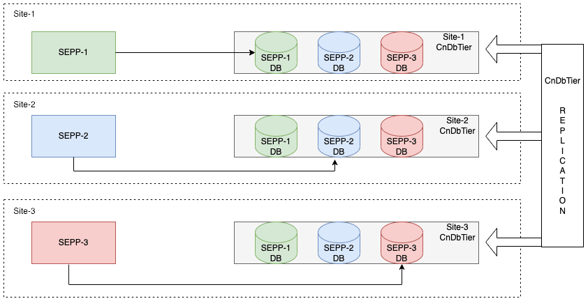
The topology has the following configurations:
Site 1: SEPP-1 communicates with SEPP-1 DB deployed in Site-1 cnDBTier.
Site 2: SEPP-2 communicates with SEPP-2 DB deployed in Site-2 cnDBTier.
Site 3: SEPP-1 communicates with SEPP-3 DB deployed in Site-3 cnDBTier.
The replication between all the cnDBTier at multiple sites are enabled.
All the configurations on each site is managed by site owners. Each site should have the same configurations for smooth switchover in case of failure.
- The consumer SEPP ensures that the original subscribing SEPP is
down.
To keep track of peer SEPP status, every SEPP instance in the georedundant deployment subscribes with NRF for receiving notifications about the change in the status of peer instances. Based on this subscription, whenever the peer SEPP comes up or goes down, NRF notifies all the other instances of the deployment.
- The DB replication must be in good health.
Managing Support for Georedundancy
To deploy SEPP in a georedundant environment:
- cnDBTier must be installed and configured for each site. For the installation procedure, see Oracle Communications Cloud Native Core DBTier Installation and Upgrade Guide.
- The Database Replication Channels between the sites must be up. For information about installing cnDBTier and parameters required for setting the DB Replication in cnDBTier custom values.yaml, see "Installing cnDBTier" and "Customizing cnDBTier" in Oracle Communications Cloud Native Core, cnDBTier Installation, Upgrade, and Fault Recovery Guide.
- Configure MySQL Database, Users and Secrets. For the configuration procedure, see "Preinstallation Tasks" in Oracle Communications Cloud Native Core, Security Edge Protection Proxy Installation, Upgrade, and Fault Recovery Guide.
- Deploy SEPP over the replicated cnDBTier sites. For information about installing and deploying SEPP, see Oracle Communications Cloud Native Core, Security Edge Protection Proxy Installation, Upgrade, and Fault Recovery Guide.
Enable Georedundancy Feature
Note:
Configuring these attributes during deployment is mandatory before enabling the georedundancy feature. Otherwise, georedundancy cannot be enabled, and SEPP at the site will act as a stand-alone SEPP.Helm Configuration for Database:
sepp-23.1.0.0.0.custom-values.yaml file for all three
sites:
global.seppDbNameglobal.seppBackupDbNameglobal.mysql.primary.hostglobal.mysql.primary.portglobal.nameSpaceglobal.mysql.primary.hostglobal.localProfile.nameglobal.localProfile.nfInstanceId
global:
  # Kubernetes Secret containing DB credentials
 dbCredSecretName: &dbCredSecretNameRef 'ocsepp-mysql-cred'

 # NameSpace where secret is deployed
 nameSpace: DEPLOYMENT_NAMESPACE
 mysql:
    primary:
      host: &mySqlHostRef "mysql-connectivity-service.site1"
      port: &mySqlPortRef 3306
  # Name of Sepp database
  seppDbName: &dbNameRef "seppdbSite1DB"
  # Name of Sepp backup database
  seppBackupDbName: "seppbackupdbSite1DB"

  nfFqdn: &nfFqdnRef "site1sepp1.inter.oracle.com"

 localProfile:
    name: "SEPP-1"
nfInstanceId: "9faf1bbc-6e4a-4454-a507-aef01a101a06"global:
# Kubernetes Secret containing DB credentials
dbCredSecretName: &dbCredSecretNameRef 'ocsepp-mysql-cred'
# NameSpace where secret is deployed
nameSpace: DEPLOYMENT_NAMESPACE
mysql:
primary:
host: &mySqlHostRef "mysql-connectivity-service.site2"
port: &mySqlPortRef 3306
# Name of Sepp database
seppDbName: &dbNameRef "seppdbSite2DB"
# Name of Sepp backup database
seppBackupDbName: "seppbackupdbSite2DB"
nfFqdn: &nfFqdnRef "site2sepp2.inter.oracle.com"
localProfile:
name: "SEPP-2"
nfInstanceId: "9faf1bbc-6e4a-4454-a507-aef01a101a07"global:
# Kubernetes Secret containing DB credentials
dbCredSecretName: &dbCredSecretNameRef 'ocsepp-mysql-cred'
# NameSpace where secret is deployed
nameSpace: DEPLOYMENT_NAMESPACE
mysql:
primary:
host: &mySqlHostRef "mysql-connectivity-service.site3"
port: &mySqlPortRef 3306
# Name of Sepp database
seppDbName: &dbNameRef "seppdbSite3DB"
# Name of Sepp backup database
seppBackupDbName: "seppbackupdbSite3DB"
nfFqdn: &nfFqdnRef "site3sepp3.inter.oracle.com"
localProfile:
name: "SEPP-3"
nfInstanceId: "9faf1bbc-6e4a-4454-a507-aef01a101a08"For more information about configuring the parameters, see Oracle Communications Cloud Native Core, Security Edge Protection Proxy Installation, Upgrade, and Fault Recovery Guide.
Following is the sample configuration at Site named "site1"
(SEPPInstanceId: 99faf1bbc-6e4a-4454-a507-aef01a101a07), which is
georedundant with Sites, "site2" (SEPPInstanceId:
99faf1bbc-6e4a-4454-a507-aef01a101a07) and "site3"
(SEPPInstanceId: 9faf1bbc-6e4a-4454-a507-aef01a101a08):
3.30.1 Two-Site Georedundancy
The following diagram depicts the topology for two-site georedundant SEPP deployment:
Figure 3-42 Two-Site Georedundancy

The two-site georedundancy is established when the cnDBTier at both sites is configured with georedundancy configurations. The cnDBTier provides bi-directional replication between both sites. When the two-sites replication is up and running, the updates done in the database at one site are replicated to the other sites in real time. The changes include creating, changing, or deleting a record.
The benefits of two-site georedundancy are:
- In case of a single site failure, the alternate site takes up the load of the failed site.
- In case of single or dual site failure (or connection failure or
any other failure), the SEPP at the active site(s) serves the consumer NFs. For
example, in a two-site redundant system with Site 1 and Site 2,
- If Site1 fails, SEPP at Site 2 serves the Consumer NF of Site 1.
- If Site2 fails, SEPP at Site 1 serves the Consumers NF of Site 2.
3.30.2 Three-Site Georedundancy
The following diagram depicts the topology for three-site georedundant SEPP deployment:
Figure 3-43 Three-Site Georedundancy

In case of three-site georedundancy, bi-directional replication is established from each site to the other two sites. The database updates from each site are replicated to the other two sites over the replication channel.
The benefits of three-site georedundancy are:
- In case of a single site failure, the remaining two sites take up the load of the failed site.
- Each site uses the SQL nodes for active and standby replication channels for high availability of the replication channels.
- In case of single or dual site failure (or connection failure or any
other failure), the SEPP in active state serves the consumer NFs. For example, in a
three-site redundant system with Site 1, Site 2, and Site 3,
- If Site 1 fails, SEPP at Site 2 and Site 3 serve the Consumer NF of Site1.
- If Site 1 and Site 2 fail, SEPP at Site 3 serves Consumer NF of Site 1 and Site 2.
When the three-sites replication is up and running, the updates done in the database at one site are replicated to the other sites in real time. The changes include creating, changing, or deleting a record.
3.30.3 Four-Site Georedundancy
The following diagram depicts the topology for four-site georedundant SEPP deployment:
Figure 3-44 Four-site Georedundancy

SEPP supports the four-site georedundant deployment. In case of four-site georedundancy, each site participates in a 4-way replication. The database updates from each site are replicated to the other three sites over the replication channels.
The advantages of four-site georedundancy are:
- In case of a single site failure, the remaining three sites keep establishing the bi-directional replication.
- Requires 6 SQL pods and 3 db-rep-svc at each site.
- Each site uses two SQL nodes for active and standby replication channels for high availability of the replication channels.
- In case of single or dual site failure (or connection failure or any
other failure), the SEPP in active state serves the consumer NFs. For example, in a
4-site redundant system with Site 1, Site 2, Site 3, and Site 4,
- If Site 1 fails, SEPP at Site 2, Site 3, and Site 4 serve the Consumer NF of Site1.
- If Site 1 and Site 2 fail, SEPP at Site 3 and Site 4 serve the Consumer NF of Site 1 and Site 2.
- If , Site 2, and Site 3 fail, SEPP at Site4 serves the Consumer NF of Site 1, Site 2, and Site 3.
When the four-site replication is up and running, the updates done in the database at one site are replicated to the other sites in real time. The changes include creating, changing, or deleting a record.
3.30.4 Managing the Feature
This section provides information about Helm, REST API, and Cloud Native Configuration Console (CNC Console) configurations required for enabling and configuring this feature.
3.30.4.1 Prerequisites
To deploy SEPP in a georedundant environment:
- cnDBTier must be installed and configured for each site. For the installation procedure, see Oracle Communications Cloud Native Core, cnDBTier Installation, Upgrade, and Fault Recovery Guide.
- The Database Replication Channels between the sites must be up. For
information about installing cnDBTier and parameters required for setting the
Database replication in
cnDBTier, see "Installing cnDBTier" and "Customizing cnDBTier" in Oracle Communications Cloud Native Core, cnDBTier Installation, Upgrade, and Fault Recovery Guide.custom values.yaml - Configure MySQL Database, Users, and Secrets. For the configuration procedure, see "Preinstallation Tasks" in Oracle Communications Cloud Native Core, Security Edge Protection Proxy Installation, Upgrade, and Fault Recovery Guide.
- Deploy SEPP over the replicated cnDBTier sites. For information about installing and deploying SEPP, see Oracle Communications Cloud Native Core, Security Edge Protection Proxy Installation, Upgrade, and Fault Recovery Guide.
3.30.4.2 Enable
Note:
Configuring these attributes during deployment is mandatory before enabling the georedundancy feature. Otherwise, georedundancy cannot be enabled, and SEPP at the site will act as a standalone SEPP.Helm Configuration for Database:
ocsepp-custom
            values-<version>.yaml
file for all four sites:
global.seppDbNameglobal.seppBackupDbNameglobal.mysql.primary.hostglobal.mysql.primary.portglobal.nameSpaceglobal.mysql.primary.hostglobal.localProfile.nameglobal.localProfile.nfInstanceId
global:
  # Kubernetes Secret containing DB credentials
 dbCredSecretName: &dbCredSecretNameRef 'ocsepp-mysql-cred'

 # NameSpace where secret is deployed
 nameSpace: DEPLOYMENT_NAMESPACE
 mysql:
    primary:
      host: &mySqlHostRef "mysql-connectivity-service.site1"
      port: &mySqlPortRef 3306
  # Name of Sepp database
  seppDbName: &dbNameRef "seppdbSite1DB"
  # Name of Sepp backup database
  seppBackupDbName: "seppbackupdbSite1DB"

  nfFqdn: &nfFqdnRef "site1sepp1.inter.oracle.com"

 localProfile:
    name: "SEPP-1"
nfInstanceId: "9faf1bbc-6e4a-4454-a507-aef01a101a06"global:
# Kubernetes Secret containing DB credentials
dbCredSecretName: &dbCredSecretNameRef 'ocsepp-mysql-cred'
# NameSpace where secret is deployed
nameSpace: DEPLOYMENT_NAMESPACE
mysql:
primary:
host: &mySqlHostRef "mysql-connectivity-service.site2"
port: &mySqlPortRef 3306
# Name of Sepp database
seppDbName: &dbNameRef "seppdbSite2DB"
# Name of Sepp backup database
seppBackupDbName: "seppbackupdbSite2DB"
nfFqdn: &nfFqdnRef "site2sepp2.inter.oracle.com"
localProfile:
name: "SEPP-2"
nfInstanceId: "9faf1bbc-6e4a-4454-a507-aef01a101a07"global:
# Kubernetes Secret containing DB credentials
dbCredSecretName: &dbCredSecretNameRef 'ocsepp-mysql-cred'
# NameSpace where secret is deployed
nameSpace: DEPLOYMENT_NAMESPACE
mysql:
primary:
host: &mySqlHostRef "mysql-connectivity-service.site3"
port: &mySqlPortRef 3306
# Name of Sepp database
seppDbName: &dbNameRef "seppdbSite3DB"
# Name of Sepp backup database
seppBackupDbName: "seppbackupdbSite3DB"
nfFqdn: &nfFqdnRef "site3sepp3.inter.oracle.com"
localProfile:
name: "SEPP-3"
nfInstanceId: "9faf1bbc-6e4a-4454-a507-aef01a101a08"global:
# Kubernetes Secret containing DB credentials
dbCredSecretName: &dbCredSecretNameRef 'ocsepp-mysql-cred'
# NameSpace where secret is deployed
nameSpace: DEPLOYMENT_NAMESPACE
mysql:
primary:
host: &mySqlHostRef "mysql-connectivity-service.site4"
port: &mySqlPortRef 3306
# Name of Sepp database
seppDbName: &dbNameRef "seppdbSite4DB"
# Name of Sepp backup
database seppBackupDbName: "seppbackupdbSite4DB"
nfFqdn: &nfFqdnRef "site4sepp4.inter.oracle.com"
localProfile:
name: "SEPP-4"
nfInstanceId: "9faf1bbc-6e4a-4454-a507-aef01a101a09"For more information about configuring the parameters, see Oracle Communications Cloud Native Core, Security Edge Protection Proxy Installation, Upgrade, and Fault Recovery Guide.
Following is the sample configuration at Site named "site1"
(SEPPInstanceId: 99faf1bbc-6e4a-4454-a507-aef01a101a07), which is
georedundant with Sites, "site2" (SEPPInstanceId:
99faf1bbc-6e4a-4454-a507-aef01a101a07) and "site3"
(SEPPInstanceId: 9faf1bbc-6e4a-4454-a507-aef01a101a08):
3.30.5 Adding a Site to an Existing SEPP Georedundant Site
This section describes the procedure to add a site to an existing SEPP site.
Prerequisites
- SEPP connected to a cnDBTier is up and running. This is referred as Site 1 or Site 2.
- SEPP and cnDBTier versions used for Site 1 and Site 2 installation must be identified and same must be used for adding another site.
Adding a site
- Install a new cnDBTier. This cnDBTier must act as a georedundant database to the cnDBTier in Site-1 or Site-2. For more information to install a cnDBTier, see Oracle Communications Cloud Native Core cnDBTier User Guide.
- Verify the replication channel between the cnDBTier sites by sending the
following request to the dbMonitor service of both the cnDBTier sites. The
responses from both the cnDBTier sites must show the status of replication
channel as
up:
curl http://<mysql-db-monitor-service>:8080/db-tier/status/replication/realtimeSample command:
curl http://mysql-cluster-db-monitor-svc:8080/db-tier/status/replication/realtimeSample output:
[{"localSiteName":"Site-1","remoteSiteName":"Site-2","remoteSiteName":"Site-3","replicationStatus":"UP","secondsBehindRemote": 0}] - Create the required secrets to install the Site-2 or Site-3 SEPP in the same namespace as the new cnDBTier installed in step-1, by following the steps described in the "Configuring Kubernetes Secret for Accessing SEPP Database" subsection from "Installing SEPP" chapter in Oracle Communications Cloud Native Core Security Edge Protection Proxy Installation, Upgrade, and Fault Recovery Guide.
- Run the following command to verify the secret
created:
$ kubectl describe secret <database secret name> -n <Namespace of SEPP deployment> - Install the Site-2 or Site-3 SEPP using the updated
ocsepp-custom values-<version>.yamlfile. For more information on installation procedure, see Oracle Communications Cloud Native Core Security Edge Protection Proxy Installation, Upgrade, and Fault Recovery Guide.Verify the installation as mentioned in Oracle Communications Cloud Native Core Security Edge Protection Proxy Installation, Upgrade, and Fault Recovery Guide.
- After the installation is complete, make sure that the "DbReplicationStatusInactive" alert is not raised in the alert dashboard. If the alert exists, verify the above configuration steps. If the alert is not present, it means the DBReplication is up and the georedundant deployment of all sites is successful.
3.30.6 Removing a Site from an Existing Georedundant Deployment
Prerequisites
- SEPP connected to a cnDBTier is up and running. This is referred as Site 1 (SEPP-1 and SEPP-2).
Procedure
This section describes the procedure to remove a site (Site1 or Site 2) from an existing georedundant SEPP deployment.
- Uninstall the SEPP instance from the site to be removed.
For more information on uninstallation procedure, see Oracle Communications Cloud Native Core, Security Edge Protection Proxy Installation, Upgrade, and Fault Recovery Guide.
- Remove the DB Replication and the NDBCluster on the site to be removed. For more information on this procedure, see Oracle Communications Cloud Native Core, cnDBTier User Guide.
3.30.7 Recovering a Failed Site
This section describes the procedure of recovering a failed site in SEPP deployment.
When any of the four sites is down or replication is broken with other sites, then perform the following procedure to restore the failed site from healthy remote site backup.
Mark the site as FAILED in remote healthy cluster
curl -i  -X POST http://<failed site replication svc IP: port>/db-tier/gr-recovery/remotesite/<failed site name>/failed

HTTP/1.1 200
Vary: Origin
Vary: Access-Control-Request-Method
Vary: Access-Control-Request-Headers
X-Content-Type-Options: nosniff
X-XSS-Protection: 0
Cache-Control: no-cache, no-store, max-age=0, must-revalidate
Pragma: no-cache
Expires: 0
X-Frame-Options: DENY
Content-Length: 0
Date: Fri, 19 Apr 2024 08:14:48 GMT
Start recovery of failed site from healthy cluster
curl -i -X POST http://<failed site replication sec IP:port>/db-tier/gr-recovery/site/<failed site name>/grbackupsite/<remote Healthy site name>/start

HTTP/1.1 200
Vary: Origin
Vary: Access-Control-Request-Method
Vary: Access-Control-Request-Headers
X-Content-Type-Options: nosniff
X-XSS-Protection: 0
Cache-Control: no-cache, no-store, max-age=0, must-revalidate
Pragma: no-cache
Expires: 0
X-Frame-Options: DENY
Content-Length: 0
Date: Fri, 19 Apr 2024 08:46:13 GMT
Monitor the fault recovery state
curl -i -X GET http://<failed site replication sec IP:port>/db-tier/gr-recovery/site/<failed site name>/status

HTTP/1.1 200
Vary: Origin
Vary: Access-Control-Request-Method
Vary: Access-Control-Request-Headers
X-Content-Type-Options: nosniff
X-XSS-Protection: 0
Cache-Control: no-cache, no-store, max-age=0, must-revalidate
Pragma: no-cache
Expires: 0
X-Frame-Options: DENY
Content-Type: application/json
Transfer-Encoding: chunked
Date: Fri, 19 Apr 2024 09:04:41 GMT

{"localSiteName":"<failed site name>","geoReplicationRecoverystatus":"COMPLETED","geoReplicationRecoverystate":"COMPLETED","remotesitesGrInfo":[{"remoteSiteName":"<remote site name1>","replchannel_group_id":"1","gr_state":"COMPLETED"},{"remoteSiteName":"<remote site name2>","replchannel_group_id":"1","gr_state":"COMPLETED"},{"remoteSiteName":"<remote site name3>","replchannel_group_id":"1","gr_state":"COMPLETED"}]}[3.31 Support for Kubernetes Resource
3.31.1 Support for Network Policies
Network Policies are an application-centric construct that allows you to specify how a pod is allowed to communicate with various network entities. To control communication between the cluster's pods and services and to determine which pods and services can access one another inside the cluster, it creates pod-level rules.
Previously, SEPP had the privilege to communicate with other namespaces, and pods of one namespace could communicate with others without any restriction. Now, namespace-level isolation is provided for the SEPP pods, and some scope of communications is allowed between the SEPP and pods outside the cluster. The network policies enforce access restrictions for all the applicable data flows except communication from Kubernetes node to pod for invoking container probe.
Managing Support for Network Policies
Enable
To use this feature, network policies need to be applied to the namespace in which SEPP is applied.
Configure
You can configure this feature using Helm. For information about configuring Network Policy for SEPP Deployment, see Oracle Communications Cloud Native Core, Cloud Native Environment Installation, Upgrade, and Fault Recovery Guide.
Observe
There are no specific metrics, KPIs, and alerts required for the Support of Network Policy functionality.
3.31.2 Pod Disruption Budget
Background
Pods are the basic units of Kubernetes and are used to deploy Cloud Native Core (CNC) Network Functions (NFs).
Pod disruption occurs due to voluntary and involuntary disruptions.
Voluntary Disruptions
Voluntary pod disruption occurs when:
- pods are removed from a cluster.
- SEPP worker nodes are drained at the time of cluster upgrade and running pods are evicted from these nodes.
- load balancing of worker nodes is performed by evenly distributing pods among worker nodes.
Involuntary Disruptions
Involuntary pod disruption occurs when:
- the system hardware or software fails.
- SEPP worker nodes are removed accidentally.
- pods are evicted due to insufficient resources on SEPP worker nodes.
Kubernetes has introduced the PodDisruptionBudgets (PDB) concept to manage pod disruption outages in the clusters. PDB is applicable only for voluntary disruptions. It is used to avoid service impact due to voluntary disruption and ensures high availability of NF.
PodDisruptionBudget (PDB) is a Kubernetes resource that allows you to achieve high availability of scalable application services when the cluster administrators perform voluntary disruptions to manage the cluster nodes. PDB restricts the number of pods that are down simultaneously from voluntary disruptions. Defining PDB is helpful to keep the services running undisrupted when a pod is deleted accidentally or deliberately. PDB can be defined for high available and scalable SEPP services such as cn32f-svc, pn32f-svc, cn32c-svc, pn32c-svc, n32-ingress-gateway, n32-egress-gateway, plmn-ingress-gateway, plmn-egress-gateway, nfmanagement-svc, nfdiscovery-svc, and perf-info services.
It allows safe eviction
of pods when a Kubernetes node is drained to perform maintenance on the node. It
uses the maxUnavailable parameter specified in the Helm chart to determine the
maximum number of pods that can be unavailable during a voluntary disruption. For
example, when a maxUnavailable is 25%, pod evictions are allowed as
long as no more than 25% of the desired pods are in unhealthy state.
For more information about this functionality, see https://kubernetes.io/docs/concepts/workloads/pods/disruptions/#pod-disruption-budgets.
Default PodDisruptionBudget for SEPP Deployment
Table 3-14 Default PodDisruptionBudget for SEPP Deployment
| Microservice | PDB Value Specified (maxUnavailable) |
|---|---|
| cn32c-svc | 25% |
| pn32c-svc | 25% |
| cn32f-svc | 25% |
| pn32f-svc | 25% |
| config-mgr-svc | Not Applicable |
| plmn-ingress-gateway | 25% |
| plmn-egress-gateway | 25% |
| n32-ingress-gateway | 25% |
| n32-egress-gateway | 25% |
| app-info | 25% |
| config-server | 50% |
| perf-info | 25% |
| nf-mediation | 25% |
Managing Pod Disruption BudgetEnable
This feature is enabled automatically if you are deploying SEPP with Release 16.
ConfigureYou can configure this feature using Helm. For information about configuring PDB, see Oracle Communications Cloud Native Core, Cloud Native Environment Installation, Upgrade, and Fault Recovery Guide.
ObserveThere are no specific metrics, KPIs, and alerts required for the support of PDB functionality.
3.32 Alternate Routing based on the DNS SRV Record for Home Network Functions
Overview
SEPP selects SCP and NRF for indirect communication of 5G messages using the static configurations done by the operator. This feature enables SEPP to route the messages to the SCP, NRF or Producer NFs using DNS SRV records, in addition to already existing static manual configuration by the operator.
SEPP supports DNS SRV based selection of SCP, NRF or Producer NFs through Egress Gateway (EGW), which supports Alternate Route Service (ARS). It enables SEPP to resolve the FQDN or Virtual FQDN to alternative FQDNs of 5G NFs. EGW uses the virtual FQDN of NF instances to query the Alternate Route Service and retrieve the list of alternative FQDNs with priorities and weight assigned to each of them. Based on the priorities, EGW selects the NF instances for rerouting attempts and distributes the incoming traffic in proportion to the weight value assigned.
Using this feature, SEPP performs alternate routing of messages by querying SRV records with the DNS server to find an alternate producer NF and route the service request. SEPP supports retrieval of NRF, SCP, and Producer NFs' records using DNS SRV queries at plmn-egress-gateway. SEPP uses either NF Set or DNS SRV records to perform alternate routing.
Support for Direct and Indirect Communication
The Consumer NF messages are routed through plmn-egress-gateway based on the 3gpp-sbi-target-apiroot header.
In the case of direct communication, the gateway service routes the messages to the FQDN or IP defined in the header. In the case of indirect communication, static peers are defined on the gateway service and the incoming requests are routed to the defined hosts if they match the routing criteria.
Figure 3-45 Direct Communication
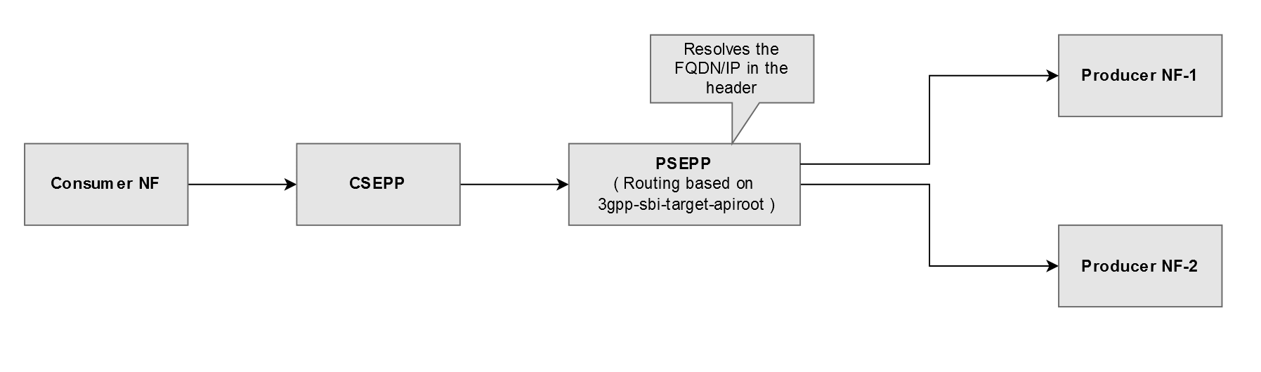
Routing to NRF, SCP, and Producer NFs Through DNS SRV
SEPP supports priority and weight based routing of the Consumer NFs requests through plmn-egress-gateway. SEPP sends a DNS SRV query request based on the virtual FQDN configured to identify peer NF instances. The DNS server returns the response with the multiple FQDNs associated with the virtual FQDN, and each FQDN can have multiple IP addresses associated to each. Further based on the DNS SRV algorithm defined at the plmn-egress-gateway, it selects the peer with the highest priority. If the priorities are same for multiple FQDN records, then the incoming requests are distributed based on the weight value assigned to them.
Below is the format of SRV records defined at DNS server:
_Service._Proto.Name TTL Class SRV Priority Weight Port Target
_http._tcp.example.com 86400 IN SRV 1 10 80 blr.example.com
In this example, the virtual FQDN "example.com" will return the single FQDN record "blr.example.com" with priority 1 and weight 10.
Similarly, multiple records can be defined against the single virtual FQDN. Each FQDN returned can be resolved to multiple IP address in the DNS server.
Figure 3-46 Routing to Producer NFs Through DNS SRV
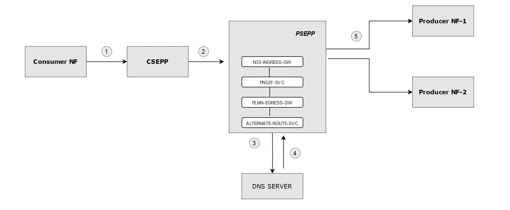
The above diagram represents the routing to Producer NFs Through DNS SRV. The flow of routing is represented by the numbering.
Design and Architecture
SEPP supports multiple deployments for SCP for routing of Consumer NF queries. When SEPP receives a request, it processes the request from Consumer NF based on the API root header configuration. PLMN Egress Gateway (EGW) performs the routing based on the SbiRouting functionality at plmn-egress-gateway and forwards the requests to the peer configuration defined in the route. This process of routing the request between SEPP through SCP is known as indirect communication.
SEPP supports alternate routing and weight based routing for virtual peer instances. In the case of virtual peer instances, SEPP identifies peer SCP instances based on the virtual FQDN and distributes the 5G traffic to NF instances based on DNS SRV algorithm defined at plmn-egress-gateway. Lower the priority, higher is the chance of selection and if multiple instances have same priority, then distribution will be based on the weight factor assigned to each of the records. In the case of failures, SEPP also supports alternate routing to the peers based on their priority.
Alternate Route Service uses the DNS SRV records for the resolution of virtual FQDN. PLMN Egress Gateway uses the virtual FQDN of peer instances to query the Alternate Route Service and get the list of alternate FQDNs with a priority and weight assigned to each one of them. The Egress Gateway selects the peer instances for routing or re-routing attempts based on this priority value assigned to the peers and distribute the traffic based on weight value if priorities are same.
- Priority Based
- Weight Based
Priority Based Routing
In priority based routing, the virtual FQDN configured for SCP instances with different priorities.
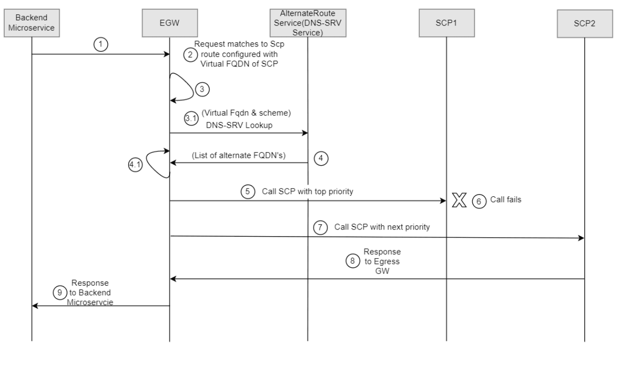
- PLMN Egress Gateway (EGW) receives a request from the backend microservice.
- PLMN EGW maps the request to a route configured with virtual FQDN of SCP. Since the route is configured with virtual FQDN of SCP, the virtual FQDN is resolved to the list of alternate FQDNs.
- PLMN EGW gets the list of FQDNs from cache data. If
cached data has not expired, Step 3 (a) and Step 4 are
skipped. If the cache has expired data in it, EGW continues
with the Step 3 (a).
- EGW calls the Alternate Route Service to resolve virtual FQDN to alternate FQDNs and puts it in the cached memory.
- PLMN EGW performs the DNS-SRV query using the
virtual FQDN & scheme.
- EGW caches the resolved virtual FQDN details.
- PLMN EGW selects the SCP instance based on the priority, and it calls the primary SCP.
- The call fails if the primary SCP is unavailable.
- Based on the error codes configured in the route,
EGW selects the SCP instance with next priority to initiate
a call.
- PLMN EGW repeats this step for all available SCP instances in the order of their priority as per the number of reroute attempts configured by the operator.
- PLMN EGW receives the response.
- PLMN EGW forwards the response to the backend micro-service as it is received.
Note:
In Step 2, if Static SCP instances are configured instead of virtual FQDN, then Step 3 & Step 4 are skipped and Steps 5 through 9 are followed.
Weight Based Routing
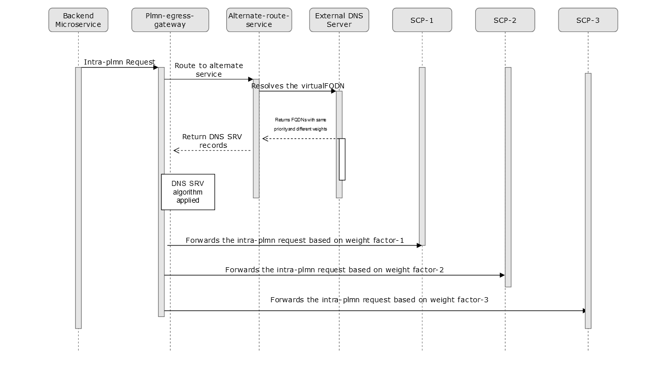
- PLMN Egress Gateway (EGW) receives a request from the backend microservice.
- PLMN EGW maps the request to a route configured with virtual FQDN of SCP. Since the route is configured with virtual FQDN of SCP, the virtual FQDN is resolved to the list of alternate FQDNs.
- PLMN EGW gets the list of FQDNs from cache data. If
cached data has not expired, Step 3 (a) and Step 4 are
skipped. If the cache has expired data in it, EGW continues
with the Step 3 (a).
- EGW calls the AlternateRoute Service to resolve virtual FQDN to alternate FQDNs and puts it in the cached memory.
- PLMN EGW performs the DNS-SRV query using the
virtual FQDN and scheme.
- EGW caches the resolved virtual FQDN details.
- PLMN EGW selects the SCP instances based on the weight factor because priorities are same, and it distributes the traffic to SCP instances in proportion to the weight factor defined.
- The call is re-routed to next peer if the primary SCPs are unavailable.
- Based on the error codes configured in the route,
EGW selects the SCP instance with next priority to initiate
a call.
- PLMN EGW repeats this step for all available SCP instances in the order of their priority as per the number of reroute attempts configured by the operator.
- PLMN EGW receives the response.
- PLMN EGW forwards the response to the backend micro-service as it is received.
Note:
In Step 2, if Static SCP instances are configured instead of virtual FQDN, then Step 3 and Step 4 are skipped and Steps 5 through 9 are followed.
Note:
This feature is not applicable for the following:- SOR (Steering of Roaming)
- Roaming Hub mode
- N32 Egress Gateway
Managing Alternate Routing based on the DNS SRV Record for Home Network Functions Feature
This section describes the procedure to enable the feature.
This feature is
enabled by setting the following helm parameters configurations in
the ocsepp_custom_values_<version>.yaml file.
dnsSrvEnabled: true
alternateRouteServiceEnable: true
dnsSrvFqdnSetting.enabled: false
dnsSrvFqdnSetting.pattern: "_{scheme}._tcp.{fqdn}."
configureDefaultRoute: true
sbiRoutingConfigMode: REST
routeConfigMode: RESTalternateRouteServiceEnable: trueFor more information, see Oracle Communications Cloud Native Core, Security Edge Protection Proxy Installation, Upgrade, and Fault Recovery Guide.
Configure
You can configure the feature using REST API.
- Configure using REST API: Perform the feature configurations as described in Egress Gateway REST APIs in Oracle Communications Cloud Native Core, Security Edge Protection Proxy REST Specification Guide.
Note:
NRF virtual path route is mandatory to route the intra-plmn request to NRF.Observe
Following are the feature specific metrics:
- oc_fqdn_alternate_route_total
- oc_dns_srv_lookup_total
- oc_alternate_route_resultset
- oc_configclient_request_total
- oc_configclient_response_total
- oc_egressgateway_sbiRouting_http_responses_total
For more information about metrics and KPIs, see SEPP Metrics and SEPP KPIs sections.
Maintain
If you encounter alerts at system or application levels, see SEPP Alerts section for resolution steps.
In case the alert still persists, perform the following:
- Collect the logs and Troubleshooting Scenarios: For more information on how to collect logs and troubleshooting information, see Oracle Communications Cloud Native Core, Security Edge Protection Proxy Troubleshooting Guide.
- Raise a service request: See My Oracle Support for more information on how to raise a service request.
3.33 Rate Limiting for Egress Roaming Signaling per PLMN
Overview
In some scenarios, SEPP may be forwarding more traffic towards a particular PLMN ID resulting in the producers of that PLMN ID getting overloaded. To control this excess traffic, SEPP has been enhanced to provide egress rate limiting based on PLMN ID, which ensures that the core network is not overloaded with traffic. Using PLMN ID to filter the number of messages limits the traffic towards the network. It prevents network congestion and improves the overall network performance.
This feature allows to configure the egress request rate on N32F interface based on the destination PLMN IDs. This controls the messages sent out from the local SEPP to a Remote SEPP.
With this feature, the number of egress requests to one or more PLMN IDs is restricted based on a configured count using token bucket algorithm. The same bucket is applicable to one or more configured PLMN IDs. The messages are counted based on the destination PLMN ID only and not destination Remote SEPP or Remote SEPP Set.
SBI Messages are discarded based on the
3gpp-Sbi-Message-Priority. Only low
priority messages are subject to being discarded. The high priority
messages are not discarded even if they breach the egress rate
limiting priority threshold. The user can configure the threshold
for 3gpp-Sbi-Message-Priority to be used for
discarding.
PLMN is identified from
3gpp-Sbi-Target-apiRoot header or
:authority header. The
:authority header is used only in absence
of 3gpp-Sbi-Target-apiRoot header.
Token Bucket Algorithm
This feature is implemented using Bucket4j, which uses Token Bucket Algorithm.
The token bucket algorithm can be described as the following:
- Token bucket algorithm processes messages only if there are tokens in the bucket.
- Bucket is filled with tokens at a user configurable rate during token consumption asynchronously.
- Tokens are removed from the bucket once the messages are processed.
- The following four configurations are required:
- Bucket Capacity - Bucket size defines the capacity to handle traffic burst.
- Refill Rate - The number of tokens which should be added to refill the bucket.
- Refill Duration - It decides how frequently the bucket needs to be refilled.
- Request Token - It defines the batch size of token requested from the corresponding bucket.
- Tokens divided by refill duration defines the traffic rate.
Detailed Description
The following diagram represents how the egress rate limiting is implemented using token bucket algorithm.
Figure 3-47 Token Bucket Algorithm

The above diagram represents the egress rate limiting for the messages received from four different PLMNS, that is, PLMN 1, PLMN 2, PLMN 3, PLMN 4.
In the above diagram, the user has configured the Bucket Capacity, Refill Rate, Refill Duration, and Request Token for the two Egress Rate Limit lists; Egress Rate Limit1 (ERL1) and ERL2. Two separate buckets are created corresponding to each list.
The "ERL List to Remaining Token Mapping" is populated from the corresponding bucket (for ERL List1 and ERL List2) using number of configured request tokens.
The PLMNs are configured as follows:
- PLMN 1 is configured under ERL List 1; the list has 6 tokens and number of request tokens is set to 2. When the request for PLMN 1 arrives, the "ERL List to Remaining Token Mapping" is populated with 2 tokens and the request consumes one of the available tokens and gets forwarded. One token remains in the mapping.
- PLMN 2 and PLMN 3 are configured under ERL List 2
where corresponding mapping or bucket has no token
available. When the requests for PLMN 2 and PLMN 3 are
raised, as there are no tokens available, the messages are
checked for their priority as follows:
- Message priority for PLMN 2 (configured as 23 in the example) is less than the configured discard message priority threshold for ERL2 (configured as 24), it is a high priority message and thus it gets forwarded.
- Message priority for PLMN 3 (configured as 25 in the example) is greater than or equal to the configured discard message priority threshold for ERL2 (configured as 24), it is a low priority message and thus it gets rejected by the rate limit feature with the user configured status code and title.
- PLMN 4 is not configured under any of the ERL lists and thus when the request for PLMN 4 arrives, the rate limit feature is considered as false for this request and thus it gets forwarded.
The following table represents the summary of the algorithm:
Table 3-15 Summary
| PLMN | Tokens in ERL List | Message Priority | Rejected/Forwarded |
|---|---|---|---|
| PLMN 1 | Token available in ERL1's bucket | Ignore priority | Forwarded |
| PLMN 2 | No token available in ERL2's bucket | High | Forwarded |
| PLMN 3 | Low | Rejected | |
| PLMN 4 | No corresponding ERL list is configured | Ignore priority | Forwarded |
Note:
The request message priority is derived as follows:- Check the request for
3gpp-Sbi-Message-Priorityheader. - If not present, check for helm configured route message priority.
- If not present, take the default priority.
Implementation
This feature is implemented at PLMN IGW in SEPP mode at the C-SEPP side. This provides egress rate limiting for all the messages originating from Local SEPP based on PLMN IDs. The diagram shows two separate token buckets applicable for Remote SEPP Set 1 and Remote SEPP Set 2. One Remote SEPP Set can cater to multiple PLMNs.
Figure 3-48 Implementation at C-SEPP

Note:
This feature is not applicable to P-SEPP in SEPP mode. The feature is implemented at N32 IGW in Roaming Hub mode.Managing Rate Limiting for Egress Roaming Signaling per PLMN Feature
This section describes the procedure to enable the feature. You can enable the feature using the Helm parameters and REST API or CNC Console.
The feature is disabled by default.
rateLimiting:
  enabled: true
  egressRateLimiter:
    enabled: true
Note:
- In SEPP mode, set the
egressRateLimiter.enabledparameter to true in the PLMN Ingress Gateway section ofocsepp_custom_values_<version>.yamlfile. - In Roaming Hub mode, set the
egressRateLimiter.enabledparameter to true in the N32 Ingress Gateway section ofocsepp_custom_values_roaming_hub_<version>.yamlfile.
For more information, see Oracle Communications Cloud Native Core, Security Edge Protection Proxy Installation, Upgrade, and Fault Recovery Guide.
CNC Console
- In the CNC Console GUI, from the left navigation menu, navigate to SEPP and then click Rate Limiting.
- Select Engress Rate Limiting which is defined under Rate Limiting screen.
- The Option and EgressRateLimitingList appears underneath.
- Click Option the option screen appears at the right pane. The Egress Rate Limiting Feature details are available in the screen.
- Set Egress Rate Limiting Enabled to True on the right pane.
REST API
Set the
egressRateLimitingEnabled as
Enabled at the Egress Rate Limiting REST
API.
Note:
In CNC Console or REST API, Egress Rate Limiting feature can be enabled and disabled globally for the complete system at run time and this can be enabled or disabled for a particular Egress Rate Limiting List also.
- If the Helm parameters
rateLimitingandegressRateLimiterare set to false, then the feature is globally disabled. - If feature is disabled on CNC Console Option screen or REST API, then the feature is globally disabled.
- If feature is disabled on CNC Console EgressRateLimitingList screen or REST API, then Egress Rate Limiting feature is disabled for that ERL list (group of PLMN IDs).
Configure
You can configure the feature using REST API and CNC Console.
- Configure using REST API: Perform the feature configurations as described in Egress Gateway REST APIs in Oracle Communications Cloud Native Core, Security Edge Protection Proxy REST Specification Guide.
- Configure using CNC Console: Perform the feature configurations as described in Configuring SEPP using CNC Console.
Observe
Following are the feature specific metrics:
- oc_ingressgateway_plmn_egress_ratelimit_total (Added with six different metric filter status)
Following are the feature specific KPIs:
- Average Number of Messages Rejected for a Particular PLMN
- Average Number of Messages Accepted for a Particular PLMN
- Average Number of Messages for which Feature not Applied
- Average of all Messages by Status
- Average Number of Messages Rejected per PLMN
- Average Number of Messages Accepted per PLMN
For more information about metrics and KPIs, see SEPP Metrics and SEPP KPIs sections.
Maintain
If you encounter alerts at system or application levels, see SEPP Alerts section for resolution steps.
In case the alert still persists, perform the following:
- Collect the logs and Troubleshooting Scenarios: For more information on how to collect logs and troubleshooting information, see Oracle Communications Cloud Native Core, Security Edge Protection Proxy Troubleshooting Guide.
- Raise a service request: See My Oracle Support for more information on how to raise a service request.
3.34 Service mesh for intra-NF communication
Oracle SEPP leverages the Istio or Envoy service mesh (Aspen Service Mesh) for all internal and external communication. The service mesh integration provides inter-NF communication and allows API gateway co-working with service mesh. The service mesh integration supports the services by deploying a special sidecar proxy in the environment to intercept all network communication between microservices.
For more information on configuring ASM, see Oracle Communications Cloud Native Core Network Repository Function Installation and Upgrade Guide.
3.35 Automated Testing Suite Support
SEPP provides Automated Testing Suite for validating the functionalities. Through Automated Testing Suite (ATS), Oracle Communications aims at providing an end-to-end solution to its customers for deploying and testing the 5G NFs. Refer to Oracle Communications Automated Testing Suite Guide for more information.