4 Configuring SEPP using CNC Console
This chapter describes how to configure different services in SEPP using Oracle Communications Cloud Native Configuration (CNC) Console.
4.1 CNC Console Interface
- In the Windows system, open the hosts file in the notepad as an
Administrator and append the following set of lines at the end:
<CNCC Node IP> cncc-iam-ingress-gateway.cncc.svc.cluster.local
<CNCC Node IP> cncc-core-ingress-gateway.cncc.svc.cluster.local
For example:10.75.212.88 cncc-iam-ingress-gateway.cncc.svc.cluster.local 10.75.212.88 cncc-core-ingress-gateway.cncc.svc.cluster.localNote:
The IP Address in the above lines may change when deployment cluster changes. - Save and close the hosts file.
Ensure that a CNC user and password are created before logging into the CNC Console. For more information on how to create a CNC Console user and password, see Oracle Communications Cloud Native Core Console Installation and Upgrade Guide.
The procedure to log in to the CNC Console is as follows:
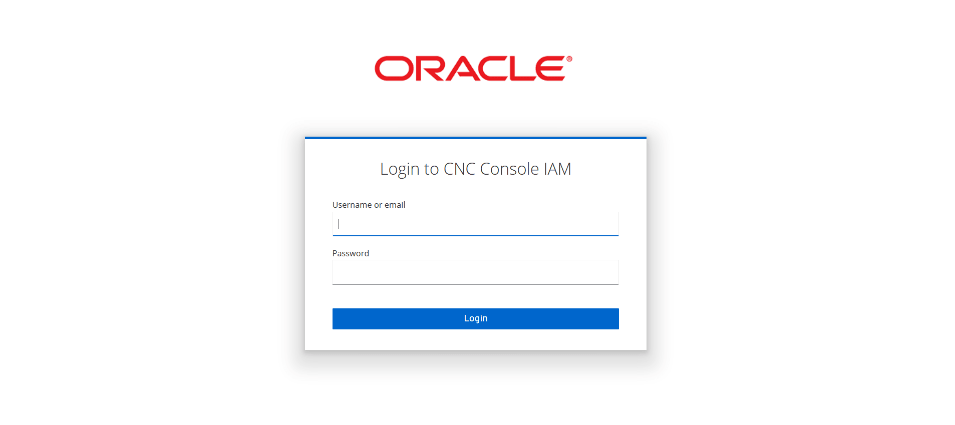
1. Open any browser.
2. Enter the URL: http://<host name>:<port number>. The Login screen appears:
Figure 4-1 Login Screen
Note:
<host name> is cncc-iam-ingress-ip and <port number> is cncc-iam-ingress-port.3. Enter the valid credentials.
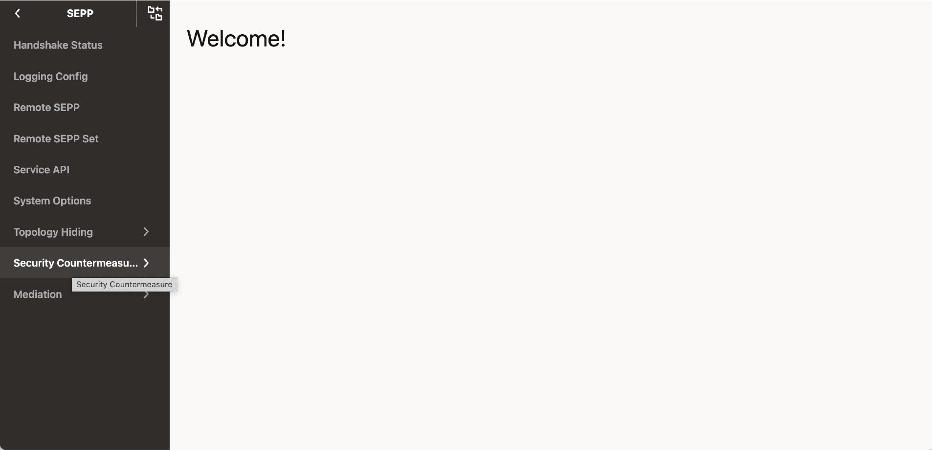
4. Click Login. The Welcome screen of CNC Console interface appears.
Figure 4-2 Welcome Page of the CNC Console

Select the required NF instance from the Please Select Instance drop-down list. The left pane displays the selected network function and on clicking the network function the corresponding APIs and configurations appears underneath.
4.2 SEPP Configuration
This section describes how to configure different SEPP features and services using CNC Console.
On selecting SEPP from the drop-down list, the following screen appears:
Figure 4-3 SEPP Welcome Screen
4.2.1 Handshake Status
Handshake Status Rest API returns the handshake status corresponding to each Remote SEPP Name.
Perform the following procedure to view the Handshake Status:
- From the left navigation menu, navigate to SEPP and then click Handshake Status. The list of all the handshake status corresponding to each SEPP Name appears on the right pane.
The parameters are:
Table 4-1 Handshake Status Parameters
| Parameter Name | Mandatory(M)/Optional(O)/Conditional(C) | Datatype | Description |
|---|---|---|---|
| Remote SEPP | M | String | Name of Remote SEPP |
| State | M | Enum | N32F Context State |
| 3GPP SBI Target API Root Header Supported | M | Boolean | Indicates whether 3GPP SBI Target API Root Header Supported or not by Remote SEPP. |
| Local PLMN ID(s) | M | Object | List of Local PLMN ID(s) supported |
| Handshake Reinit Status | M | Enum | Status of Reinitiated Handshake when changing local PLMN ID(s) or editing Remote SEPP configuration. |
| HandshakeTimestamp | M | Time format | This parameter displays time of handshake and time is updated if handshake is reinitiated. |
Note:
Possible handshake states are CAPABILITY_EXCHANGE_STATE and N32F_ESTABLISHED_STATE.- CAPABILITY_EXCHANGE_STATE - Handshake initiated with the remote SEPP.
- N32F_ESTABLISHED_STATE - Handshake completed and TLS connection is established with remote SEPP.
4.2.2 Logging Config
Logging Config allows the user to configure the application based log level and package based log level.
The Logging Config can be configured into SEPP mode and IPX mode. To enable the SEPP mode, set the operationMode flag to true. To enable the IPX mode, set the operationMode flag to false. In IPX mode,the user cannot enable or disable the log level for nfmanagement and nfdscovery services.
Perform the following procedure to configure the log levels:
- From the left navigation menu, navigate to SEPP and then click Logging Config.
- On selecting Logging Config, the list of all application logs, package logs, and their levels configured in the system appear on the right pane.
- Click Edit icon to modify the log level. The page is enabled for modification.
- Click View to view the details of the log level List.
Table 4-2 Logging Config Parameters
| Parameter Name | Enabled/Available | Mandatory(M)/Optional(O)/Conditional(C) | Datatype | Description | |
|---|---|---|---|---|---|
| Listing Screen | Edit Screen | ||||
| ServiceType | Yes | Yes | M | Enum | Name of the Common Service - N32 EGW, N32 IGW, PLMN EGW, PLMN IGW |
| Application Log Level | Yes | Yes | M | Enum | Log level for the application |
| Package Log Level | Yes | Yes | M | String | Log level of each corresponding packages. Example: For Package root, the loglevel can be ERROR. |
The supported log levels are - ERROR, WARN, INFO, DEBUG, and TRACE.
Table 4-3 Log levels
| Log Level | Description |
|---|---|
| ERROR | Designates error events that might still allow the application to continue running. |
| WARN | Designates potentially harmful situations. |
| INFO | Designates informational messages that highlight the progress of the application at a coarse-grained level. |
| DEBUG | Designates fine-grained informational events that are most useful to debug an application. |
| TRACE | Designates finer-grained informational events than the DEBUG. |
4.2.3 Remote SEPP
Remote SEPP returns all the configured Remote SEPP profiles.
- From the left navigation menu, navigate to SEPP and then click Remote SEPP. The list of all the Remote SEPPs configured along with the parameters appear on the right pane.
- Click Edit icon to modify a specific parameter. The page is
enabled for modification.
The parameters are:
Note:
- SEPP Name and FQDN cannot be edited.
- N32F FQDN, N32F IP Address, and N32F Port values must be added in the Remote SEPP to enable separate port configurations for n32c and n32f on the Egress routes feature.
- Virtual Host value must be added in the Remote SEPP to enable load sharing among multiple Remote SEPP nodes feature.
Table 4-4 Remote SEPP Parameters
Parameter Name Mandatory(M)/Optional(O)/Conditional(C) Data Type Description Name M String Name of the Remote Sepp PLMN ID(s) M Object List of PLMN ID - MCC and MNC Domain O String Domain for routing. Default value: mncxxx.mccyyy.3gppnetwork.org SEPP FQDN M String Fully Qualified Domain Name for SEPP Security Capability List O List <SecurityCapa bility> Type of security capability supported - TLS and PRINS Is Enabled O Boolean Remote SEPP is True (enabled) or False (disabled). Default value: False Port O Integer Port for SEPP NF API Prefix M String API Prefix Default Value: "" API Version O String API Version priority O Integer This parameter is currently not in use and is reserved for future release. Remote SEPP IP Address O String This is the Remote SEPP IP Address. If Remote SEPP IP is provided, it will be added in authority header while sending HTTP2 headers towards Remote SEPP. If Remote SEPP IP is not provided, FQDN is resolved to the corresponding IP endpoint using DNS. Hence, DNS configuration should be present for the FQDN. In this case, the authority header contains FQDN. sanValidationRequired O Boolean San validation is enabled for incoming N32C handshake request or not. N32F FQDN O String This parameter describes the FQDN used for the forwarding plane. This will be configured only if control plane and forwarding plane FQDNs are different. N32F IP Address O String This parameter describes the IP Address used for the forwarding plane. This will be configured only if control plane and forwarding plane configuration are different. N32F Port O String This parameter describes the port used for the forwarding plane. This will be configured only if control plane and forwarding plane configuration are different. Virtual Host O String This parameter describes the virtual FQDN used for the load sharing between the remote SEPPs. - Click Delete icon to delete a specific Remote SEPP Profile.
- Click Add from the top right side to add a new Remote SEPP Profile.
- Click Save.
Note:
Name, SEPP FQDN, and PLMN ID(s) are mandatory parameters.
4.2.4 Remote SEPP Set
Remote SEPP Set allows the user to configure the Remote SEPP Sets.
- From the left navigation menu, navigate to SEPP and then click Remote SEPP Set. On selecting Remote SEPP Set, the list of all the Remote Sepp Sets configured in the system appears on the right pane.
- Click Edit icon to modify the parameters. The page is enabled for modification.
- Click Add to add a new Remote SEPP Set. PrimarySepp,
SecondarySepp, and TertiarySepp can be added.
Note:
- One Remote Sepp Set will be created per PLMN and this set can have up to three producer SEPPs sharing same PLMN. The three producer SEPPs can be configured in this set based on their priority as either Primary, Secondary, or Tertiary.
- The user must configure atleast one of the Primary, Secondary, or Tertiary parameters.
The parameters are:
Table 4-5 Remote SEPP Set Parameters
| Parameter Name | Data type | Mandatory(M)/ Conditional(C)/ Optional(O) | Description |
|---|---|---|---|
| Name | String | M | Name of Remote SEPP Set |
| Primary SEPP | String | C | The name of Primary SEPP Configured in Set, which is treated as the primary route in the forward plane. |
| Secondary SEPP | String | C | The name of Secondary SEPP configured in Set, which is treated as the secondary route in the forward plane. |
| Tertiary SEPP | String | C | The name of Tertiary SEPP configured in Set, which is treated as the tertiary route in the forward plane. |
| Allowed List Name | String | M | Allowed List Name supported by Remote SEPPs Set. |
| CAT 2 Network ID Validation | String | M | It contains CAT 2 Network ID Validation Configuration parameters for this RSS |
| Network ID in Header Validation Enabled | Boolean | M |
A Boolean value to enable and disable the Network ID in Header Validation feature at RSS level. true indicates Enabled false indicates Disabled |
| Network ID in Body Validation Enabled | Boolean | M |
A Boolean value to enable and disable the Network ID in Body Validation feature at RSS level. true indicates Enabled false indicates Disabled |
| Network ID Validation List Name | String | M | Network ID Validation List Name supported by this Remote SEPP Set |
| Hosted SEPP | Object | M | It contains Hosted SEPP Configuration parameters for this RSS |
| Allowed Producer Remote SEPP Sets | String | M | List of Allowed Producer Remote SEPP Sets |
| Ingress Rate Limiting | Object | M | It contains Ingress Rate Limiting Configuration parameters for this RSS |
| RSS Ingress Rate Limiting Enabled | Boolean | O |
A Boolean value to enable and disable the Ingress Rate Limiting feature at this RSS level. true indicates Enabled false indicates Disabled |
| Bucket Capacity | Integer | C |
Integer Number for setting the Bucket Capacity as an input for Token Bucket Algorithm. Bucket size defined the capacity to handle traffic burst. |
| Refill Rate | Integer | C | Refill Rate to define the number of tokens to be added to refill the bucket |
| Refill Duration | Integer | C | Duration to decide how frequently to refill bucket |
| Request Token | Integer | C | Request Token to define the Pre loaded tokens to refill the bucket |
| Error Configuration | Object | M | Error Configuration for Ingress Rate Limiting feature limited to this RSS |
| Action | String | C | By Default Reject is selected as SBI Request will be rejected with the user configured Error Configuration when the number of SBI requests is above the configured limit. |
| Status code | Integer | C | Error Status Code to be used in the Error Response for discarding the SBI requests when the number of SBI requests is above the configured limit. |
| Title | String | C | Error Title to be used in the Error Response for discarding the SBI requests when the number of SBI requests is above the configured limit. |
| Mediation | Object | M | It contains Mediation Configuration parameters for this RSS |
| Trigger Rule List Name | String | Trigger List Name supported by this Remote SEPP Set. | |
| SoR | Object | M | It contains SOR Configuration parameters for this RSS |
| SoR Trigger Rule Enabled | Boolean | M | Enables or disables the SOR trigger rules. |
| SoR Trigger Rule List Name | Integer | M | SOR Trigger Rule List Name supported by this Remote SEPP Set |
| PLMN ID(s) | Integer | M | PLMN ID(s) supported by Remote SEPPs in Set. PLMN ID includes MCC and MNC |
| Allowed List Name | string | M | Allowed List Name supported by Remote SEPPs Set. |
| Trigger Rule List Name | string | M | Trigger List Name supported by Remote SEPPs Set. |
| Message Validation on Body Enabled | boolean | M |
A Boolean value to enable or disable the Message Validation on Body at RSS level. true indicates enabled false indicates disabled |
| Message Validation On Query Parameters Enabled | boolean | M |
A Boolean value to enable and disable the Message Validation on Query Parameters at RSS level. true indicates enabled false indicates disabled |
| Message Validation List | String | M | MessageValidation List Name supported by Remote SEPPs Set. |
| Allowed List Name | String | M | Allowed List Name supported by Remote SEPPs Set. |
| Trigger Rule List Name | String | M | Trigger List Name supported by Remote SEPPs Set. |
| Previous Location check Enabled | Boolean | C |
A Boolean value to enable and disable the Cat 3 - Previous Location check feature at RSS Level. true indicates Enabled false indicates Disabled |
| Previous Location Trigger List | String | C | Previous Location Trigger List Name supported by Remote SEPPs Set. |
Note:
- Remote SEPP Sets are created per PLMN. It consists of minimum 1 and maximum 3 Remote SEPP in Primary-Secondary-Tertiary mode and used for N32F SBI message routing.
- The user must configure atleast one of the Primary, Secondary, or Tertiary parameters.
4.2.5 Service APIs
The Service API is used to add, view, and delete the complete set of REST APIs supported by SEPP.
- From the left navigation menu, navigate to SEPP and then click Service APIs. The list of all the REST APIs supported by SEPP appears on the right pane.
- Click Add from the top right side to add or delete the
supported REST APIs.
The parameters are:
Table 4-6 Service APIs
Parameter Name Mandatory(M)/Optional(O)/Conditional(C) Datatype Description Resource URIs M String 5G Service Based Resource URI HTTP Method M Enum Resource URI Method ( GET,POST,PUT,PATCH,DELETE,OPTIONS, HEAD) Regular Expression M String Regular Expression for matching Resource URI
4.2.6 System Options
The System Options and Remote SEPP Set option allows the user to enable and configure the Hosted SEPP feature.
Perform the following procedure to do the Hosted SEPP configurations:
- From the left navigation menu, navigate to SEPP and then click System Options.
- Click Allowed P-RSS Validation Options under System Options, the System Options page appears on the right pane.
- Set Enable Allowed P-RSS Validation to True to enable the Hosted SEPP feature.
- From the left navigation menu, navigate to SEPP and then click Remote SEPP Set option for configuring Hosted SEPP feature.
- Click Edit icon to modify the specific parameter. User can add or delete Allowed Producer Remote SEPP Sets. This is the list of Remote SEPP Sets that are allowed for communication with Consumer Remote SEPP Set.
The parameters are:
Table 4-7 System Options Parameter
| Parameter Name | Mandatory(M)/Optional(O)/Conditional(C) | Datatype | Description |
|---|---|---|---|
| Enable Allowed P-RSS Validation | O | Boolean |
A Boolean value to enable and disable the Hosted SEPP Feature. True indicates Enabled False indicates Disabled. The feature is disabled (set to false) by default. |
Table 4-8 Remote SEPP Set Parameters
| Parameter Name | Mandatory(M)/Optional(O)/Conditional(C) | Datatype | Description |
|---|---|---|---|
| Allowed Producer Remote SEPP Sets | O | List of String | List of Remote SEPP Sets which are allowed for communication with Consumer Remote SEPP Set |
4.2.7 Topology Hiding
Topology Hiding option allows the user to set Topology Hiding feature as
ENABLED or DISABLED and configure the topology
options.
- From the left navigation menu, navigate to SEPP and then click Topology Hiding. Select the Option.
- Click Edit icon to modify the Option. The Edit Option page appears.
- Set the Topology Hiding to True or False.
The parameters
are:
Table 4-9 Topology Hiding Parameters
Parameter Name Mandatory(M)/Optional(O)/Conditional(C) Datatype Description Topology Hiding O Boolean A Boolean value to enable and disable the Topology Hiding feature. True indicates Enabled False indicates Disabled. The feature is disabled (set to false) by default.
Topology Configuration Options
Topology framework provides the options at the CNC Console screen while processing the request/response json format messages.
- From the left navigation menu, navigate to SEPP and then select Topology Hiding. The Option appears underneath the topology hiding on the left menu.
- Click on Option, the Option screen appears.
- User can configure Action and Enable Multiple
PsuedoValue.
Table 4-10 Topology Hiding Parameters
Parameter Name Mandatory(M)/Optional(O)/Conditional(C) Datatype Description Enable Multiple Pseudo Value O Boolean This is a boolean field. If set to true, signifies that if more than one actual value exists in the request/response then every actual value occurence is replaced by unique pseudo value. The value is disabled (set to false) by default. Action M Enum Action has two possible values FORWARD and REJECT. By default we have FORWARD enabled. Status Code M Integer User can configure the required HTTP error code when exceptions arise due to the TH operation failures. Title M String User can configure the required Title when exceptions arise due to the TH operation failures. Note:
Action has two possible values FORWARD and REJECT. By default we have FORWARD enabled.
FORWARD: While any exception occurs processing the message for TH/TUH, the original message is forwarded as if no TH/TUH is enabled and operation should be success.
REJECT: While any exception occurs processing the message for TH/TUH, the original message is dropped with the error body having status code and error description as configured in the CNCC screen.
If in case REJECT is selected and statusCode and Error Description is not given or left empty, then status code is set as 500 and error description as "Internal error" by default.
Note:
Enable Multiple PseudoValue is set as false by default and user can set to true to enable the special processing. If the system has many occurrence of same actual value in the request/response then this property gives the flexibility that each same actual value must be replaced with the unique different pseudo value. This can only be possible if we define at least 7 different pseudo values in actual to pseudo mappings as we pick different values from this mappings only. Also if same actual value occurs more than 7 times then there is a possibility of repetition since we only have maximum of 7 distinct values.
Enable Multiple PseudoValue property works on request and response separately. Request and response processing are two different operations and should be treated as the isolated operations.
Pseudo Values
The Pseudo Values option appears underneath the Topology Hiding. This Pseudo Values option allows the user to set the pseudo values against an actual value.
- From the left navigation menu, navigate to SEPP and then select Topology Hiding. The Pseudo Values appears underneath the topology hiding on the left menu.
- Click on Pseudo Values, the list of all the actual values and corresponding pseudo values configured in the system along with their Value Type.
- Click Add to add the actual value and corresponding pseudo
values.
Note:
Actual Value, Pseudo Value, and Value Type are mandatory parameters.Note:
If the actual value contains mnc and mcc values as in 3gpp-sbi-target-apiRoot, then pseudo values must also contain mnc and mcc. - Click Save.
The parameters are:
Table 4-11 Pseudo Value Configuration Parameters
| Attribute | Mandatory(M)/Optional(O)/Conditional(C) | Datatype | Description |
|---|---|---|---|
| actualValue | M | string | Refers to the actual FQDN of network functions. |
| pseudoValues | M | string | Refers to the pseudo value corresponding to a configured actual value of network functions. |
| value type | M | Enum | Refers to the type of actual and pseudo values. Example: FQDN, NF SERVICE ID, NF SERVICE INSTANCE ID, OTHERS. OTHERS is for the values which do not fit in first three categories. |
Header and Body Configurations
- From the left navigation menu, navigate to SEPP and then select Topology Hiding. The Header and Body IE options appears underneath the topology hiding on the left menu.
- Click Header, theHeader screen appears on the right pane.
- Click Add, the Create Header appears and user can add the header information.
- User can add the new header parameters.
Note:
Header Name, Regular Expression, Trigger Point ,and Operation are the header parameters. - Click Body IE, the Topology Body screen appears on the right pane.
- Click Add, the Topology Body Configuration appears
and user can add the body information.
Note:
Method, API Resource, Identifier ,Regular Expression, Trigger Point ,and Operation are the body parameters. - Click Save.
Table 4-12 Header Configuration Parameters
| Attribute | Mandatory(M)/Optional(O)/Conditional(C) | Data type | Description |
|---|---|---|---|
| Header Name | M | String | Name of the header |
| Regular Expression | M | String | Regular Expression for the header |
| Trigger Point | M | Enum | Request Ingress, Response Ingress, Request Egress, Response Egress |
| Operation | M | Enum | Topology Hiding or Topology Recovery |
Table 4-13 Body IE Configuration Parameters
| Attribute | Mandatory(M)/Optional(O)/Conditional(C) | Data stype | Description |
|---|---|---|---|
| API Resource | M | String | API Resource that comes from default table |
| Identifier | M | String | Body IE Key Identifier |
| Regular Expression | M | String | Regular Expression for the Body IE |
| Trigger Point | M | Enum | Request Ingress, Response Ingress, Request Egress, Response Egress |
| Operation | M | Enum | Topology Hiding /Topology Recovery |
| Method | M | Enum | GET/PUT/POST/DELETE/PATCH |
4.2.8 Security Countermeasure
The Security Countermeasure option is used to enable and configure the Cat-0 SBI Message Schema Validation feature, Cat 1 -Service API Validation feature, Cat 2 – Network ID Validation feature, and Cat 3 – Previous Location Check feature.
The Service API Allowed List REST API is used to do the configurations on the allowed list of REST APIs.
4.2.8.1 Cat 1 -Service API Validation
The Security Countermeasure option is used to enable the Cat 0 - SBI Message Schema Validation feature, Cat 1 -Service API Validation feature, Cat 2 – Network ID Validation feature, and Cat 3 - Previous Location Check feature.
Perform the following procedure to do the Cat 1 -Service API Validation configurations:
- From the left navigation menu, navigate to SEPP and then click Security Countermeasure.
- Click Cat 1 -Service API Validation under Security Countermeasure, Option page appears on the right pane.
- Set Security Countermeasure parameter to True to enable the Cat 1 -Service API Validation feature.
- Click Service API Allowed List under Cat 1 -Service API Validation, the Service API Allowed List page appears on the right pane.
- Click Add from the top right side to add or update the allowed REST APIs and supported methods.
The parameters are:
Table 4-14 Cat 1 -Service API Validation
| Parameter Name | Mandatory(M)/Optional(O)/Conditional(C) | Data Type | Description |
|---|---|---|---|
| Enable Cat 1 - Service API Validation | O | Boolean | A Boolean value to enable and disable the Cat 1 - Service API Validation feature. true indicates enabled false indicates disabled. The feature is disabled (set to false) by default. |
Table 4-15 Service API Allowed List
| Parameter Name | Sub Parameter | Enabled | Mandatory(M)/Optional(O)/Conditional(C) | Data Type | Description | |
|---|---|---|---|---|---|---|
| Listing Screen | Edit Screen | |||||
| Allowed List Name | Yes | Yes | M | String | Allowed list name per Remote SEPP Set | |
| N32 Ingress | Yes | Yes | M | Object | Ingress Direction | |
| Resource URI | No | Yes | M | String | Resource URI | |
| HTTP Method | No | Yes | M | Enum | Resource URI Method ( GET,POST,PUT,PATCH,DELETE,OPTIONS, HEAD) | |
| N32 Egress | Yes | Yes | M | Object | Egress Direction | |
| Resource URI | No | Yes | M | String | Resource URI | |
| HTTP Method | No | Yes | M | Enum | Resource URI Method ( GET,POST,PUT,PATCH,DELETE,OPTIONS, HEAD) | |
| N32 Ingress Action | Yes | Yes | M | Object | Ingress Action | |
| Title | No | Yes | M | String | Title for the Error Configuration | |
| Status Code | No | Yes | M | Integer | Default Value 406 | |
| Action | No | Yes | M | Enum | Whenever a failure happens, request will be rejected with the user configured action. Default value is Reject. | |
| N32 Egress Action | M | Object | Egress Action | |||
| Title | No | Yes | M | String | Title for the Error Configuration | |
| Status Code | No | Yes | M | Integer | Default Value 406 | |
| Action | No | Yes | M | Enum | Whenever a failure happens, request will be rejected with the user configured action. Default value is Reject | |
4.2.8.2 Cat 2 – Network ID Validation
The Security Countermeasure option is used to enable the Cat 0 - SBI Message Schema Validation feature, Cat 1 -Service API Validation feature, Cat 2 – Network ID Validation feature, and Cat 3 - Previous Location Check feature.
Perform the following procedure to enable or disable the Cat 2 -Network ID Validation feature:
- From the left navigation menu, navigate to SEPP, and then click Security Countermeasure.
- Click Cat 2 -Network ID Validation under Security Countermeasure, the Option, Cat 2 -Network ID Validation List, Header, and Body IE appears underneath.
- Click Option, the Option page appears on the right pane. The Cat 2 – Network ID Validation feature enabling details are available on the screen.
- Click Edit icon to modify the Option. The Edit Option page appears.
- Set the Network ID in Header Validation Enabled to True or False.
- Set the Network ID in Body Validation Enabled to True or False.
The parameters are:
Table 4-16 Cat 2 -Network ID Validation
| Parameter Name | Mandatory(M)/Optional(O)/Conditional(C) | Data Type | Description |
|---|---|---|---|
| Network ID in Header Validation Enabled | M | Boolean |
A Boolean value to enable and disable the Network ID in Header Validation feature at global level. True- Enabled False- Disabled |
| Network ID in Body Validation Enabled | M | Boolean |
A Boolean value to enable and disable the Network ID in Body Validation feature at global level. True- Enabled False- Disabled |
- From the left navigation menu, navigate to SEPP, and then click Security Countermeasure.
- Click Cat 2 -Network ID Validation under Security Countermeasure, the Option, Cat 2 -Network ID Validation List , Header, and Body IE appears underneath.
- Click Cat 2 -Network ID Validation List , the Cat 2 -Network ID Validation List page appears on the right pane.
- Click Add to add a new Cat 2 -Network ID Validation List. The Add Cat 2 -Network ID Validation List page appears and user can add theNetwork ID Validation List information.
- Enter Network ID Validation List Name.
- Enter Ingress Rules with HTTP Method and Resource URI.
- Enter Egress Rules with HTTP Method and Resource URI.
- Enter Ingress Error Action and Egress Error Action.
Table 4-17 Network ID Validation List
| Parameter Name | Mandatory(M)/Optional(O)/Conditional(C) | Data Type | Description |
|---|---|---|---|
| Network ID Validation List Name | M | String | A string value to represent a Network ID Validation List Name |
Table 4-18 Ingress and Egress Error Action Parameters
| Parameter Name | Mandatory(M)/Optional(O)/Conditional(C) | Data Type | Description |
|---|---|---|---|
| Action | M | Enum | Error Action in case of Network ID Validation Failure (REJECT, FORWARD) |
| Status Code | M | Integer | Error Status Code to be returned in case of Network ID Validation Failure |
| Title | M | String | Error Title in case of Network ID Validation Failure |
Adding Ingress Rules and Egress Rules
- Click Network ID Validation List, the Network ID Validation List page appears on the right pane.
- Click Add to add a new Network ID Validation List. The Add Network ID Validation List page appears and user can add the Network ID Validation List information.
- To add Ingress Rules, click Add icon for the Ingress rules.
- A new page, Add Ingress Rules, opens to Add Ingress Rules with HTTP Method and Resource URI as configurable parameters. Select the desired HTTP Method and Resource URI from the drop down menu.
- To add Egress Rules, click Add icon for the Egress rules.
- A new page, Add Egress Rules, opens to Add Egress Rules with HTTP Method and Resource URI as configurable parameters. Select the desired HTTP Method and Resource URI from the drop-down menu.
Table 4-19 Ingress Rules and Egress Rules Parameters
| Parameter Name | Mandatory(M)/Optional(O)/Conditional(C) | Data Type | Description |
|---|---|---|---|
| HTTP Method | M | Enum |
Enums with the following allowed values: POST, PUT, GET, PATCH, DELETE, OPTION, HEAD |
| Resource URI | M | String | Resource URI for which PLMN ID Validation will take place. |
Header Configuration
Perform the following procedure to View Header Configuration.
- From the left navigation menu, navigate to SEPP, and then select Security Countermeasure.
- Then select Cat 2 – Network ID Validation.
- The Header option appears underneath.
- Click Header, the Header screen appears at the right pane. The Header details are available on the screen.
The parameters are:
Table 4-20 Header Configuration
| Parameter Name | Mandatory(M)/Optional(O)/Conditional(C) | Data Type | Description |
|---|---|---|---|
| Resource URI | M | String | Resource URI for which PLMN ID Validation happens. |
| HTTP Method | M | Enum |
Enums with the following allowed values: POST, PUT, GET, PATCH, DELETE, OPTION, HEAD |
| Header Name | M | String | Header Name for which PLMN ID validation should happen |
| Regular Expression | M | String | Regular Expression to Fetch PLMN ID (MCC & MNC) |
| Associated SEPP Type | M | Enum | CSEPP or PSEPP |
| MNC Length | M | Integer | Indicates the length of mnc. It can be two or three. |
Perform the following procedure to Add Header Configuration.
- From the left navigation menu, navigate to SEPP, and then select Security Countermeasure.
- Select Cat 2 – Network ID Validation.
- The Header screen appears underneath.
- Click Header, the Header screen appears at the right pane. The Header details are available on the screen.
- Click Add to add a new Header. The Add Header screen appears and user can add the Header information.
The parameters are:
Table 4-21 Add Header Configuration
| Parameter Name | Enabled Listing Screen | Enabled Edit Screen | Mandatory(M)/Optional(O)/Conditional(C) | Data Type | Description |
|---|---|---|---|---|---|
| Resource URI | Yes | Yes | M | String | Resource URI for which PLMN ID Validation will happen |
| HTTP Method | Yes | Yes | M | Enum |
Enums with the following allowed values: POST, PUT, GET, PATCH, DELETE, OPTION, HEAD |
| Header Name | Yes | Yes | M | String | Header Name for which PLMN ID validation should happen |
| Regular Expression | Yes | Yes | M | String | Regular Expression to Fetch PLMN ID (MCC & MNC) |
| Associated SEPP Type | Yes | Yes | M | Enum | CSEPP or PSEPP |
| MNC Length | Yes | Yes | M | Integer | Indicates the length of mnc. It can be two or three. |
Body IE Configuration
Perform the following procedure to View Body IE Configuration.
- From the left navigation menu, navigate to SEPP, then select Security Countermeasure.
- Then select Cat 2 – Network ID Validation.
- The Body IE screen appears underneath.
- Click Body IE, the Body IE screen appears at the right pane. The Body IE details are available on the screen.
The parameters are:
Table 4-22 Body IE Configuration
| Parameter Name | Mandatory(M)/Optional(O)/Conditional(C) | Data Type | Description |
|---|---|---|---|
| Resource URI | M | String | Resource URI for which PLMN ID Validation will happen |
| HTTP Method | M | Enum |
Enums with the following allowed values: POST, PUT, GET, PATCH, DELETE, OPTION, HEAD |
| Body IE Key | M | String | Body IE Key for which PLMN ID validation should happen |
| Associated SEPP Type | M | Enum | CSEPP or PSEPP |
| Regular Expression | M | String | Regular Expression to Fetch PLMN ID (MCC and MNC) |
| MNC Length | M | Integer | Indicates the length of mnc. It can be two or three. |
Perform the following procedure to Add Body IE Configuration:
- From the left navigation menu, navigate to SEPP, and then select Security Countermeasure.
- Then select Cat 2 – Network ID Validation.
- The Body IE screen appears underneath.
- Click Body IE, the Body IE screen appears at the right pane. The Body IE details are available on the screen.
- Click Add to add a new Body IE. The Add Body IE screen appears and user can add the Body IE information.
The parameters are:
Table 4-23 Add Body IE Configuration Parameters
| Parameter Name | Mandatory(M)/Optional(O)/Conditional(C) | Data Type | Description |
|---|---|---|---|
| Resource URI | M | String | Resource URI for which PLMN ID Validation will happen |
| HTTP Method | M | Enum |
Enums with the following allowed values: POST, PUT, GET, PATCH, DELETE, OPTION, HEAD |
| Body IE Key | M | String | Body IE Key for which PLMN ID validation should happen |
| Associated SEPP Type | M | Enum | CSEPP or PSEPP |
| Regular Expression | M | String | Regular Expression to Fetch PLMN ID (MCC and MNC) |
| MNC Length | M | Integer | Indicates the length of mnc. It can be two or three. |
4.2.8.3 Cat 0 - SBI Message Schema Validation
The Security Countermeasure option is used to enable the Cat 0 - SBI Message Schema Validation feature, Cat 1 -Service API Validation feature, Cat 2 – Network ID Validation feature, and Cat 3 - Previous Location Check feature.
Perform the following procedure to do the Cat 0- SBI Message Schema Validation feature configurations:
Options screen
- From the left navigation menu, navigate to SEPP and then click Security Countermeasure.
- Click Cat 0 - SBI Message Schema Validation feature under Security Counter Measure, the Option appears underneath.
- Click Option, the option screen appears at the right pane. The Cat 0 - SBI Message Validation feature details are available in the screen.
- Click Edit icon to modify the Option. The Edit Option page appears
- Set the Message Validation on Body Enabled and Message Validation on Query Parameters Enabled to True.
- Set the Maximum Request Size (KB) as per the requirement, default value is set as 40 KB.
- Set the Maximum Number of Query parameters as per the requirement, default value is set as 100.
The parameters are:
Table 4-24 Cat 0 - SBI Message Schema Validation feature (Options Screen) Parameters
| Parameter Name | Datatype | Mandatory(M)/Conditional(C)/Optional(O) | Description |
|---|---|---|---|
| Message Validation On Body Enabled | boolean | O |
A boolean value to enable or disable the message validation on body at global level. true indicates enabled false indicates disabled |
| Message Validation On Query Parameters Enabled | boolean | O |
A boolean value to enable and disable the message validation on Query Parameters at global level. true indicates enabled false indicates disabled |
| Maximum Request Size (KB) | integer | O | Provides maximum allowed request body size. Default value: 40 KB |
| Maximum Number of Query parameters | integer | O | Provides maximum number of allowed query parameters. Default Value: 100 |
- From the left navigation menu, navigate to SEPP and then click Security Countermeasure.
- Click Cat 0 - SBI Message Schema Validation feature under Security Countermeasure, the Message Validation List appears underneath.
- Click Message Validation List , the Message Validation List screen appears at the right pane.
- Click Edit icon to modify the Option. The Edit Option page appears
- The user can edit or add the Message Validation List.
- Click Edit icon to modify the Option. The Edit Option page appears. The Message Validation List can be edited.
- Click Add to add a new Message Validation List. The Add Message Validation List page appears, and the user can add the new Message Validation List information.
- The user can add Message Validation List Name, Ingress Rules with HTTP Method and Resource URI, Egress Rules with HTTP Method and Resource URI (Not allowed in Roaming Hub mode), Ingress Error Action, and Egress Error Action.
The parameters are:
Table 4-25 Message Validation List Parameters
| Parameter Name | Datatype | Mandatory(M)/Conditional(C)/Optional(O) | Description |
|---|---|---|---|
| Message Validation List Name | string | M | Represents a Message Validation List Name |
Ingress Error Action and Egress Error Action Parameters:
Table 4-26 Ingress Error Action and Egress Error Action Parameters
| Parameter Name | Datatype | Mandatory(M)/Conditional(C)/Optional(O) | Description |
|---|---|---|---|
| Action | String | M | Error action in the case of Message Validation failure. Range: REJECT, FORWARD |
| Status Code | String | M | Error status code to be returned in case of Message Validation failure. |
| Title | String | M | Error Title in case of Message Validation failure. |
Adding Ingress Rules and Egress Rules
- Click Message Validation List, the Message Validation List page appears on the right pane.
- Click Add to add a new Message Validation List. The Add Message Validation List page appears and user can add the Message Validation List information.
- To add Ingress Rules, click Add icon for the Ingress rules.
- A new page, Add Ingress Rules, opens to Add Ingress Rules with HTTP Method and Resource URI as configurable parameters. Select the desired HTTP Method and Resource URI from the drop down menu.
- To add Egress Rules, click Add icon for the Egress rules.
- A new page, Add Egress Rules, opens to Add Egress Rules with HTTP Method and Resource URI as configurable parameters. Select the desired HTTP Method and Resource URI from the drop down menu.
Table 4-27 Ingress Rules and Egress Rules Parameters
| Parameter Name | Mandatory(M)/Optional(O)/Conditional(C) | Datatype | Description |
|---|---|---|---|
| HTTP Method | M | Enum |
Enums with the following allowed values: POST, PUT, GET, PATCH, DELETE, OPTION, HEAD |
| Resource URI | M | String | Resource URI for which Message validation happens. |
Message Schema Configuration Screen
Perform the following procedure to view and update Message Schema Configuration.
- From the left navigation menu, navigate to SEPP and then select Security Countermeasure.
- Select Cat 0 - SBI Message Validation.
- The Message Schema Configuration option appears underneath.
- Click Message Schema Configuration, the Message Schema Configuration screen appears at the right pane. The Message Schema Configuration details are available in the screen.
- Click Add to add a new Resource URI, HTTP Method, and corresponding JSON schema.
- Select a Resource URI from dropdown.
- Select a HTTP Method from dropdown.
- Enter Corresponding resolved Message Schema in JSON format.
Perform the following procedure to delete a existing Resource URI and HTTP Method and corresponding Message Schema:
- From the left navigation menu, navigate to SEPP and then select Security Countermeasure.
- Select Cat 0 - SBI Message Validation.
- The Message Schema Configuration option appears underneath.
- Click Message Schema Configuration, the Message Schema Configuration screen appears at the right pane. The Message Schema Configuration details are available in the screen.
- Select HTTP Method, and Resource URI to be deleted and click Delete to delete a Resource URI, HTTP Method, and corresponding JSON schema.
- The message "Do you want to delete the record" appears. Click OK.
Table 4-28 Message Schema Configuration Parameters
| Parameter Name | Mandatory(M)/Optional(O)/Conditional(C) | Datatype | Description |
|---|---|---|---|
| Resource URI | M | String | Resource URI |
| HTTP Method | M | Enum | Resource URI Method ( GET,POST,PUT,PATCH,DELETE,OPTIONS, HEAD) |
| Message Schema(JSON) | M | Object | Message Schema |
4.2.8.4 Cat 3 - Previous Location Check
The Security Countermeasure option is used to enable the Cat 0 - SBI Message Schema Validation feature, Cat 1 -Service API Validation feature, Cat 2 – Network ID Validation feature, and Cat 3 - Previous Location Check feature.
Perform the following procedure to do the Cat 3 - Previous Location Check feature configurations (The Option and Trigger List appears underneath) :
Option Screen Configuration
- From the left navigation menu, navigate to SEPP and then click Security Countermeasure.
- Click Cat 3 - Previous Location Check feature under Security Countermeasure, the Option appears underneath.
- Click Option, the option screen appears at the right pane. The Cat 3 - Previous Location Check feature details are available in the screen.
- Click Edit icon to modify the Option. The Edit Option page appears
- Set the Previous Location Check Enabled to True.
- Set the Cache Refresh Timer (milliseconds) as per the requirement. The default value is set as 5000.
The parameters are:
Table 4-29 Cat 3 - Previous Location Check feature (Option Screen) Parameters
| Parameter Name | Datatype | Mandatory(M)/Conditional(C)/Optional(O) | Description |
|---|---|---|---|
| Previous Location Check Enabled | boolean | M |
A boolean value to enable or disable the Cat 3 - Previous Location Check feature at global level. true indicates enabled false indicates disabled Default Value: false |
| Cache Refresh Timer (milliseconds) | integer | M |
An integer value to set the cache refresh timer. After this timer expiry, PN32F fetch the UE authentication status from UDR for the UE ID received in Ingress Request. Default value: 5000 |
Trigger List screen allows the user to configure a set of rules for which Cat-3 Previous Location Check happens.
Perform the following procedure to view a Previous Location Trigger List:
- From the left navigation menu, navigate to SEPP and then click Security Countermeasure.
- Click Cat 3 - Previous Location Check feature under Security Countermeasure, the Trigger List appears underneath.
- Click Trigger List, the Cat 3 - Previous Location Trigger List screen appears at the right pane. The Cat 3 - Previous Location Check feature details are available on the screen.
- Click Add to add a new Previous Location Trigger List. The Create Cat 3- Previous Location Trigger List page appears and user can add the Previous Location Trigger List information.
- Enter Name, N32 Ingress Rules with HTTP Method, Resource URI, Error Action, and Exception Action.
Trigger List parameters are:
Table 4-30 Trigger List parameters
| Parameter Name | Data Type | Mandatory(M)/Conditional(C)/Optional(O) | Description |
|---|---|---|---|
| Name |
String |
M | Represents a Previous Location Trigger List Name.
Default Value: Blank |
Error Action Parameters:
Table 4-31 Error Action Parameters
| Parameter Name | Data Type | Mandatory(M)/Conditional(C)/Optional(O) | Description |
|---|---|---|---|
| Action |
Enum |
M | Error action, in case of Previous Location Check Validation failure. Range: REJECT, FORWARD. Default Value: REJECT |
| Status Code |
Integer |
M | Error Status Code to be returned, in case of Previous Location Check Validation failure. Status codes 401 and 407 are not supported at present. Default Value: 406 |
| Title |
String |
M | Error title, in case of Previous Location Check Validation
failure.
Default Value: CAT 3 Previous Location Check Failed |
Exception Action Parameters:
Table 4-32 Exception Action Parameters
| Parameter Name | Data Type | Mandatory(M)/Conditional(C)/Optional(O) | Description |
|---|---|---|---|
| Action |
Enum |
M | Exception action, in case of Previous Location Check Exception failure Range: REJECT, FORWARD. Default Value: REJECT |
| Status Code |
Integer |
M | Exception Status Code to be returned, in case of Previous Location Check Exception failure. Status codes 401and 407 are not supported at present. Default Value: 406 |
| Title |
String |
M | Exception title, in case of Previous Location Check Exception
failure.
Default Value: CAT 3 Previous Location Check Failed due to exception |
Add N32 Ingress Rules screen
- To add N32 Ingress Rules, click Add.
- Add N32 Ingress page opens to add Ingress Rules with HTTP Method and Resource URI as configurable parameters.
- Select the desired HTTP Method and Resource URI from the drop-down menu.
The parameters are:
Table 4-33 HTTP Method and Resource URI
| Parameter Name | Data Type | Mandatory(M)/Conditional(C)/Optional(O) | Description |
|---|---|---|---|
| HTTP Method | Enum | M |
Enums with the following allowed values: POST, PUT, GET, PATCH, DELETE, OPTION, HEAD |
| Resource URI | String | M | Resource URI for which Previous Location Check validation happens. |
Header Configuration screen allows the user to configure Headers for which Previous Location Check Validation happens:
Perform the following procedure to configure Serving Network ID Header Configuration.
- From the left navigation menu, navigate to SEPP and then click Security Countermeasure.
- Click Cat 3 - Previous Location Check feature under Security Countermeasure, the Trigger List appears underneath.
- Click Header, the Serving Network ID and UE ID appears underneath.
- Click Serving Network ID, the Serving Network ID Header details are available in the screen.
- Click Add to add a new header. The Add Serving Network ID Header page appears and user can add the Header information.
The parameters are:
Table 4-34 Header Parameters
| Parameter Name | Data Type | Mandatory(M)/Conditional(C)/Optional(O) | Description |
|---|---|---|---|
| Resource URI | String | M | Resource URI for which Previous Location Check validation happens. |
| HTTP Method | ENUM | M |
Enums with the following allowed values: POST, PUT, GET, PATCH, DELETE, OPTION, HEAD. |
| Header Name | String | M | Header Name for which Previous Location Check validation happens. |
| Regular Expression | String | M | Regular expression to fetch Serving Network ID (MCC and MNC). |
UE ID Header
Perform the following procedure to configure the UE ID Header Configuration:
- From the left navigation menu, navigate to SEPP and then click Security Countermeasure.
- Click Cat 3 - Previous Location Check feature under Security Countermeasure, the Trigger List appears underneath.
- Click Header, the Serving Network ID and UE ID appears underneath.
- Click Serving Network ID, the Serving Network ID Header details are available in the screen.
- Click Add to add a new Body IE. The Add Serving Network ID Header page appears and user can add the Header information.
- Click UE ID, the UE ID Header details are available in the screen.
- Click Add to add a new Header. The Add UE ID page appears and user can add the UE ID information.
The parameters are:
Table 4-35 UE ID Header Parameters
| Parameter Name | Data Type | Mandatory(M)/Conditional(C)/Optional(O) | Description |
|---|---|---|---|
| Resource URI | String | M | Resource URI for which Previous Location Check validation happen. |
| HTTP Method | ENUM | M |
Enums with the following allowed values: POST, PUT, GET, PATCH, DELETE, OPTION, HEAD. |
| Header Name | String | M | Header Name for which Previous Location Check validation should happen. |
| Regular Expression | String | M | Regular Expression to fetch UE ID. |
Body IE Configuration
Perform the following procedure to configure the Serving Network ID Body IE Configuration:
- From the left navigation menu, navigate to SEPP and then click Security Countermeasure.
- Click Cat 3 - Previous Location Check feature under Security Countermeasure, the Body IE appears underneath.
- Click Body IE, the Serving Network ID and UE ID appears underneath.
- Click Serving Network ID, the Serving Network ID Body IE details are available in the screen.
- Click Add to add a new Body IE. The Add Serving Network ID Body IE page appears and user can add the Body IE information.
The parameters are:
Table 4-36 Serving Network ID Body IE Parameters
| Parameter Name | Data Type | Mandatory(M)/Conditional(C)/Optional(O) | Description |
|---|---|---|---|
| Resource URI | String | M | Resource URI for which Previous Location Check validation will happen |
| HTTP Method | ENUM | M |
Enums with the following allowed values: POST, PUT, GET, PATCH, DELETE, OPTION, HEAD |
| Body IE Key | String | M | Body IE Key Name for which Previous Location Check validation should happen |
| Regular Expression | String | M | Regular Expression to Fetch Serving Network ID (MCC & MNC) |
Perform the following procedure to configure the UE ID Body IE Configuration:
- From the left navigation menu, navigate to SEPP and then click Security Countermeasure.
- Click Cat 3 - Previous Location Check feature under Security Countermeasure, the Body IE appears underneath.
- Click Body IE, the Serving Network ID and UE ID appears underneath.
- Click UE ID, the UE ID Body IE details are available in the screen.
- Click Add to add a new UE ID. The Add UE ID Body IE page appears and user can add the UE ID information.
The parameters are:
Table 4-37 UE ID Body IE Configuration Parameters
| Parameter Name | Data Type | Mandatory(M)/Conditional(C)/Optional(O) | Description |
|---|---|---|---|
| Resource URI | String | M | Resource URI for which Previous Location Check validation happens. |
| HTTP Method | ENUM | M |
Enums with the following allowed values: POST, PUT, GET, PATCH, DELETE, OPTION, HEAD. |
| Body IE Key | String | M | Body IE key name for which Previous Location Check validation should happen. |
| Regular Expression | String | M | Regular Expression to fetch UE ID. |
4.2.9 Mediation
The mediation option allows the user to set Mediation feature as
ENABLED or DISABLED and configure the mediation
options.
- From the left navigation menu, navigate to SEPP and then click Mediation. The options appears underneath.
- Click Options, the options screen appears at the right pane. The Mediation Feature and Error Configuration details are available in the screen.
- Click Edit icon to modify the Options. The Edit Options page appears.
- Set the Mediation Feature to True or False and configure the
Error Configuration parameters Action, Status Code, and
Title.
The parameters are:
Mediation Options
Parameter Name Enabled Mandatory(M)/Optional(O)/Conditional(C) Datatype Description Listing Screen Edit Screen Enable Mediation Yes Yes O Boolean A Boolean value to enable and disable the Mediation feature. true indicates Enabled false indicates Disabled. The feature is disabled (set to false) by default. Error Configuration Yes Yes M Object Error Configuration details
Mediation Trigger Rule List Configuration
Mediation Trigger Rule Configuration screen allows the user to configure a set of trigger rules which act as a filtering criteria for SEPP to send a particular request for mediation.
Perform the following procedure to configure the trigger rules:
- From the left navigation menu, navigate to SEPP and then select Mediation. The Trigger Rule List appears underneath.
- Click Trigger Rule List, the list of all the existing rules and corresponding configurations appears.
- Click Add to add the Trigger Rule List. The Add Trigger
Rules page appears and user can add the Trigger Rule information.
Note:
HTTP Method, Resource URI, Trigger Point, and Group Id are the Trigger Rule parameters. - Click Edit to modify the rule list. The Edit Trigger Rules page appears and user can update the Trigger Rule information.
Error Configuration Parameters
Table 4-38 Error Configuration Parameters
| Parameter Name | Enabled | Mandatory(M)/Optional(O)/Conditional(C) | Datatype | Description | |
|---|---|---|---|---|---|
| Listing Screen | Edit Screen | ||||
| Title | Yes | Yes | M | String | Error Title in case of getting error from mediation service |
| Action | Yes | Yes | M | Enum | Error Action to be performed in case of getting error from mediation service (Reject, Continue). |
| StatusCode | Yes | Yes | M | Integer | Error Status Code to be returned in case of getting error from mediation service. |
Mediation Trigger Rules List Parameters
Table 4-39 Mediation Trigger Rules List Parameters
| Parameter Name | Enabled | Mandatory(M)/Optional(O)/Conditional(C) | Datatype | Description | |
|---|---|---|---|---|---|
| Listing Screen | Edit Screen | ||||
| Name | Yes | Yes | M | String | Name of Trigger Rule List |
| Trigger Rules | No | Yes | M | Object | List of Trigger Rules |
| Trigger Rule List Type | Yes | Yes | M | Enum | Type of TRL (Local /Remote) |
| Match All Enabled | Yes | Yes | M | Boolean | Match All Enabled (true/false) |
| Match All GroupId | No | Yes | M | String | Match All Group Id |
| Match All Trigger Points | No | Yes | M | Enum | Match All Trigger Points |
Trigger Rule Parameters
Table 4-40 Trigger Rule Parameters
| Parameter Name | Enabled | Mandatory(M)/Optional(O)/Conditional(C) | Datatype | Description | |
|---|---|---|---|---|---|
| Listing Screen | Edit Screen | ||||
| HTTP Method: | No | Yes | M | Enum | Resource URI Method ( GET,POST,PUT,PATCH,DELETE,OPTIONS) |
| Resource URIs: | No | Yes | M | String | Resource URI |
| Trigger Points: | No | Yes | M | Enum | List of Trigger Point ( "N32_Egress_Request", "N32_Ingress_Response", "N32_Ingress_Request", "N32_Egress_Response") |
| Group Id: | No | Yes | M | String | Group ID for which mediation configuration is to be done. This is passed to the Mediation Service for grouping similar rules. |
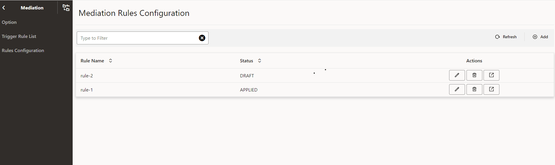
Mediation Rules Configuration
Rules configuration screen allows the user to compile, create, update, delete, clone and apply the mediation rules using CNCC.
Perform the following procedure to configure the mediation rules:
- From the left navigation menu, navigate to SEPP and then select Mediation. The Rules Configuration screen appears underneath.
- Click Rules Configuration, the list of all the existing
rules with corresponding status appears.
Figure 4-4 Mediation Rules Configuration Screen
- Click Add to add a new rule. The Add Mediation Rule
page appears and user can add the mediation rule information.
Figure 4-5 Add Mediation Rule Screen
 .
.Note:
Rule Name, Format, Status, Mediation Mode, Code, and State are the mediation rule parameters. - Click Edit button of an existing rule to modify that rule.
The Edit Mediation Rule page appears and user can edit the rule information.
Figure 4-6 Edit Mediation Rule Screen

- Click Delete button of an existing rule to delete that rule, confirmation dialog box appears and user can click OK to delete the rule or Cancel to cancel the deletion.
- Click View button of an existing rule to view the rule’s details.
Table 4-41 Rules Configuration Parameters
| Parameter Name | Mandatory(M)/Optional(O)/Conditional(C) | Datatype | Description |
|---|---|---|---|
| Rule Name | M | String | Mediation rule name |
| Status | M | Enum | Mediation rule status: APPLIED or DRAFT |
| State | M | Enum |
Compile, Clone, Save, Draft, Apply The user can select one of these states. |
| Mediation Mode | M | Enum |
MEIDATION_ACTIVE: its only applicable to mediation microservice active mode MEDIATION_TEST: its only applicable to mediation microservice test mode The user is required to configure the mediation rules using MEDIATION_ACTIVE mediation mode. MEDIATION_TEST mode is only for internal purpose. |
| Code | M | String |
Mediation rule code content. The user has to prepend the following data block along with the needed rules in the code section and save to create the rule in DRAFT status. If the user wants to apply the rule on mediation microservice then user can edit the rule and save it again with Apply state. |
| Format | M | Enum | Rule format. Only DRL is supported currently. |
| New Rule Name | C | String | New rule name is to be given only when state is clone. |
Note:
- The rule name for a rule in the DRAFT status must be unique. Otherwise, the new rule overwrites the old one.
- The new rule is always created and saved with DRAFT status in the database. User needs to save the rule with APPLY state to apply the rule to mediation microservice.
4.2.10 Ingress Rate Limiting
Ingress Rate Limiting screen allows the user to configure the global parameters for ingress rate limiting feature. Perform the following procedure to enable and configure the ingress rate liming feature:
Ingress Rate Limiting: Remote SEPP Set
- From the left navigation menu, navigate to SEPP and then click Ingress Rate Limiting. The Remote SEPP Set option appears underneath.
- Click Remote SEPP Set under Ingress Rate Limiting, the Options appears underneath.
- Click Options under Remote SEPP Set, the Options page appears on the right pane.
- Click Edit icon to modify the Option. The Edit Option page appears. The Ingress Rate Limiting feature configurations are available in the screen.
- Set Originating Network ID Header as “3gpp-Sbi-Asserted-Plmn-Id” or “3gpp-Sbi-Originating-Network-Id” or both.
- Set Remote SEPP Set Ingress Rate Limiting Enabled as true or false.
- Enter Bucket Capacity, Refill Rate, Refill Duration, and Request Tokens.
- Under Error Configuration, Enter Action as Reject.
- Enter Status Code and Title.
Table 4-42 Ingress Rate Limiting: Remote SEPP Set Parameters
| Parameter Name | Datatype | Mandatory(M)/ Conditional(C)/ Optional(O) | Description |
|---|---|---|---|
| Originating Network ID Header | Enum | M |
This parameter can have the following allowed values: 3gpp-Sbi-Asserted-Plmn-Id, 3gpp-Sbi-Originating-Network-Id |
| Remote SEPP Set Ingress Rate Limiting Enabled | Boolean | O |
A Boolean value to enable and disable the Ingress Rate Limiting feature at global level. true indicates Enabled false indicates Disabled. The feature is disabled (set to false) by default. |
| Bucket Capacity | Integer | M |
Integer Number for setting the Bucket Capacity as an input for Token Bucket Algorithm. Bucket size defined the capacity to handle traffic burst. |
| Refill Rate | Integer | M | Refill Rate to define the number of tokens to be added to refill the bucket |
| Refill Duration | Integer | M | Duration to decide how frequently to refill bucket |
| Request Token | Integer | M | Request Token to define the Pre loaded tokens to refill the bucket |
| Action | String | M | By Default Reject is selected as SBI Request will be rejected with the user configured Error Configuration when the number of SBI requests is above the configured limit. |
| Status Code | Integer | M | Error Status Code to be used in the Error Response for discarding the SBI requests when the number of SBI requests is above the configured limit. |
| Title | String | M | Error Title to be used in the Error Response for discarding the SBI requests when the number of SBI requests is above the configured limit. |
4.2.11 Egress Rate Limiting
Egress Rate Limiting screen allows the user to configure the global parameters for egress rate limiting feature. Perform the following procedure to enable and configure the egress rate liming feature:
Egress Rate Limiting
Perform the following procedure to enable the Egress Rate Limiting:
- In the CNC Console GUI, from the left navigation menu, navigate to SEPP and then click Rate Limiting.
- Select Engress Rate Limiting which is defined under Rate Limiting screen.
- The Option and EgressRateLimitingList appears underneath.
- Click Option, the option screen appears at the right pane. The Egress Rate Limiting Feature details are available in the screen.
- Set Egress Rate Limiting Enabled to True on the right pane.
Table 4-43 Egress rate limiting Option Parameters
| Attribute | Data Type | Description |
|---|---|---|
| EgressRateLimitingEnabled | boolean | This is a mandatory parameter.
Enables
or disables the Egress Rate limiting.
true indicates Enabled. false indicates Disabled. Default Value: False |
Perform the following procedure to view a Egress Rate Limiting List:
- In the CNC Console GUI, from the left navigation menu, navigate to SEPP and then click Rate Limiting.
- Select Egress Rate Limiting which is defined under Rate Limiting screen.
- The Option and EgressRateLimitingList appears underneath.
- Click EgressRateLimitingList, the EgressRateLimitingList screen appears at the right pane.
Perform the following procedure to add an Egress Rate Limiting List:
- In the CNC Console GUI, from the left navigation menu, navigate to SEPP and then click Rate Limiting.
- Select Egress Rate Limiting which is defined under Rate Limiting screen.
- The Option and EgressRateLimitingList appears underneath.
- Click EgressRateLimitingList, the EgressRateLimitingList screen appears at the right pane. The Egress Rate Limiting feature details are available on the screen.
- Click Add to add a new Egress Rate Limiting List. The Create Egress Rate Limiting List page appears. User can add the Egress Rate Limiting List information.
- Enter Egress Rate Limiting List Name.
- Under Egress Rate Limiting Configurations section, enter the list configurations; enter Enabled, Discard Message Priority, Bucket Capacity, Refill Rate, Refill duration, and Request Tokens.
- Under Error Configuration section, enter the error configuration details; enter Action, Enter Status Code, and Title.
- Under Remote Sepp Set or PLMN ID(s) section, select the Remote SEPP Set name or add PLMN IDs for the Egress Rate Limiting List.
Table 4-44 Parameter List
| Parameter Name | Data Type | Description |
|---|---|---|
| Name | String | This is a mandatory parameter. Indicates the Egress Rate Limiting List Name |
| Enabled | boolean |
This is a mandatory parameter. A boolean value to enable or disable the feature at egress rate limiting list level. This will be disabled by default. |
| Discard Message Priority | integer |
This is a mandatory parameter. Integer value to indicate the message priority used to decide if a message shall be dropped or not when rate limiting is enforced.
It the value is not provided in REST API , 0 will be used as default value of integer. |
| Bucket Capacity | integer |
This is a mandatory parameter. Integer number for setting the Bucket Capacity as an input for Token Bucket Algorithm. Bucket size defined the capacity to handle traffic burst. |
| Refill Rate | integer |
This is a mandatory parameter. Refill Rate to define the number of tokens to be added to refill the bucket
|
| Refill Duration | integer |
This is a mandatory parameter. Duration to decide how frequently to refill bucket. |
| Request Tokens | integer |
This is a mandatory parameter. Request Tokens defines the batch size of token requested from the corresponding bucket. Its recommended that the value should be configured as:
|
| Action | Enum |
This is a mandatory parameter. Error Action to be used in the Error Response while discarding the requests for Egress Rate Limiting Action supported is 'REJECT' |
| Status Code | integer |
This is a mandatory parameter. Error Status Code to be used in the Error Response for discarding the requests due to Egress Rate Limiting Configured Status Code is sent back in the HTTP/2 response message |
| Title | String |
This is a mandatory parameter. Error Title to be used in the Error Response for discarding the requests for Egress Rate Limiting. Configured Title is sent back in the HTTP/2 response message. |
| Remote Sepp Set | Enum |
This is a conditional parameter. Remote SEPP Set name in the place of PLMN ID(s), in this case the feature is applied to the PLMN IDs of the given Remote SEPP Set. Either RSS or PLMN IDs can be selected. |
| PLMN ID(s) | Enum |
This is a conditional parameter. PLMN IDs which need to be part of Egress Rate Limiting List on which feature needs to be applied. Either PLMN IDs or RSS can be selected. It's value must be in mcc-mnc format. |
Perform the following procedure to edit an Egress Rate Limiting List:
- In the CNC Console GUI, from the left navigation menu, navigate to SEPP and then click Rate Limiting.
- Select Egress Rate Limiting which is defined under Rate Limiting screen.
- The Option and EgressRateLimitingList appears underneath.
- Click EgressRateLimitingList the option screen appears at the right pane. The Egress Rate Limiting Feature details are available in the screen.
- Click Edit option. The Edit Egress Rate Limiting List page appears and user can edit the Egress Rate Limiting List information.
- You can edit the Egress Rate Limiting List Configurations and click Save.
Perform the following procedure to delete an Egress Rate Limiting List:
- In the CNC Console GUI, from the left navigation menu, navigate to SEPP and then click Rate Limiting.
- Select Egress Rate Limiting which is defined under Rate Limiting screen.
- The Option and EgressRateLimitingList appears underneath.
- Click EgressRateLimitingList the option screen appears at the right pane. The Egress Rate Limiting Feature details are available in the screen.
- Click Delete option in front of an existing Egress Rate Limiting List that you want to delete.
- "Do you want to delete the record" message appears. Click OK.
4.2.12 SOR
The SOR option allows the user to set SOR feature as enabled or disabled and configure the SOR options. Perform the following procedure to enable and configure the SOR feature:
- From the left navigation menu, navigate to SEPP and then click SOR. The Options and Trigger Rule List appear underneath.
- Click Options under SOR, the Options page appears on the right pane.
- Click Edit icon to modify the Option. The Edit Option page appears.
- Set SOR Enabled parameter to True to enable the SOR feature.
- Set Redirection enabled to true or false to enable or disable the redirection and user can configure the http code.
- Set Alternative Routing enabled to true or false to enable or disable the redirection and user can configure the http code.
- Set Retry to NF on SOR Server Error Enabled to true or false to enable or disable the retry to SOR.
- Configure SOR Server(s) by configuring Priority, Http Scheme, and other parameters..
- Configure the Redirection, Alternative Routing Options, SOR Server Error, and Custom Error.
Options Parameters
Table 4-45 Options Parameters
| Attribute | Data type | Mandatory(M)/ Conditional(C)/ Optional(O) | Description |
|---|---|---|---|
| SOR Enabled | Boolean | O | To enable or disable the SOR feature. true indicates enabled and false indicates disabled. The feature is disabled (set to false) by default. |
| Alternate Routing Enabled | Boolean | O | To enable or disable the alternative SOR option. true indicates enabled and false indicates disabled. The value is disabled (set to false) by default. |
| Retry to NF on SOR Server Error Enabled | Boolean | O | To enable or disable the retry, in case of an error from SOR producer NF occurs. true indicates enabled and false indicates disabled. |
| Redirection: Enabled | Boolean | O |
If this parameter is enabled, then SOR responds to SEPP and SEPP sends request to producer. If this parameter is disabled, then SOR sends request to producer directly. true indicates enabled and false indicates disabled. |
| Redirection: codes | String | M | This parameter is used to configure all the 3xx HTTP response code that contain valid location header parameter in response, for which user wants to get the redirection applied. |
| servers: priority | Enum | M | SOR server priority must be Primary, Secondary, and Tertiary. The first entry will always be saved as PRIMARY in database. |
| servers: httpScheme | Enum | M | The scheme can be http or https. |
| servers: sorFqdn | String | M | Indicates the FQDN of SOR Server |
| servers: sorPort | String | M | Indicates the Port of SOR Server |
| servers: apiPrefix | String | M | Indicates the API Prefix for SOR Server |
| servers: serverHeader | String | M | Server header that is expected to be received from SOR Server. Typically, SOR-<SOR FQDN> |
| Alt Routing options: Timeout | integer | M | Indicates the timer to set for retries towards SOR. |
| Alt Routing options: MaxRetry | integer | M | Indicates the number of times to retry towards the primary SOR end point. |
| SoR Server Errors: errorCodes | string | M | This is the list of expected response codes (multiple 5xx response codes seperated by (,) can be configured. Example: 501,504,510) from SOR that will need SEPP to contact the Producer directly in case of retry to producer is enabled. |
| SoR Server Errors: exceptions | string | M | The exceptions that are expected to be returned from SoR in case of timeout. |
| Custom Error: status code | string | M | Error code that will be relayed to consumer in case of SOR Timeout. |
| Custome Error: Title | string | M | Error Message that will be relayed to consumer in case of SOR Timeout. |
- From the left navigation menu, navigate to SEPP and then click SOR. The Options and Trigger Rule List appear underneath.
- Click Trigger Rule List under SOR, the Trigger Rule List page appears on the right pane.
- Click Add to add the Trigger Rule List.
- Select a combination of HTTP Method and Resource URI from the drop down list and Save.
Trigger Rule List Parameters
Table 4-46 Trigger Rule List Parameters
| Attribute | Data type | Mandatory(M)/ Conditional(C)/ Optional(O) | Description |
|---|---|---|---|
| Trigger Rule List | String | M | Name of the SOR Trigger List |
| URI List: resourceURI | String | M | List of Resource URI |
| URI List: httpMethod | String | M | Request URI httpMethod. The Range is: POST, PUT, GET, PATCH, DELETE, OPTIONS, and HEAD. |
4.2.13 cnDBTier
- In the CNC Console GUI, from the left navigation menu, navigate to SEPP and then click Configurations. The Gateway and cnDBTier appears underneath.
- click cnDBTier tab. The cnDBTier page is displayed.
- Click the Backup List to view the list of completed
backups along with backup ID, backup size, and backup creation timestamp.
The Backup List page is displayed.
Note:
The following are read-only APIs.Table 4-47 Backup List
Fields Description Site Name This attribute displays the name of the current site to which SEPP is connected. Backup Details This attribute displays the following information like backup id, backup size, and backup creation timestamp. Backup Id This attribute displays the ID of the stored backup. Backup Size (bytes) This attribute displays the size of the stored backup. Creation TimeStamp This attribute displays the time recorded when the backup was stored. - Click cnDBTier Health to view the health
status of the microservices such as replication, backup manager, monitor
services, NDB services.
The cnDBTier Health page is displayed.
- Click the Backup Manager Health Status to
view the health status of the backup manager.
The Backup Manager Health Status page is displayed.
Note:
The following are read-only APIs.Table 4-48 Backup Manager Health Status
Attribute Description Service Name This attribute displays the service name of the backup manager microservice. Service Status This attribute displays the service status of the backup manager microservice. Possible values are UP and DOWN.
DB Connection Status This attribute displays the database connection status of the backup manager microservice. Possible values are UP and DOWN.
Overall Backup Manager Service Health This attribute displays the overall health status of the backup manager microservice. Possible values are UP and DOWN.
Backup Executor Health Status This attribute displays the following information like node id and DB connection status of the backup executor. Node Id This attribute displays the id of the node. DB Connection Status This attribute displays the backup executor database connection status with the nodes. Possible values are UP and DOWN.
- Click the Monitor Health
Status to view the health status of the
services.
The Monitor Health Status page is displayed.
Note:
The following are read-only APIs.Table 4-49 Monitor Health Status details
Attribute Description Service Name This attribute displays the service name of the monitor microservice. DB Connection Status This attribute displays the database connection status of the monitor microservice. Possible values are UP and DOWN.
Metric Scrape Status This attribute displays the status of the metric scrape, that is if the metrics are fetched or not. If the metrics are fetched then the service is up and vice versa. Possible values are UP and DOWN.
Overall Monitor Service Health This attribute displays the overall health status of the monitor microservice. Possible values are UP and DOWN.
- Click the NDB Health Status
to view the health status of the network database.
The NDB Health Status page is displayed.
Note:
The following are read-only APIs.Table 4-50 NDB Health Status details
Attribute Description Local Site Name This attribute displays the name of the current site (Site 1, Site 2 ). NDB Health Status Details This attribute displays the health status of the network database such as the name of the NDB service, status of the service, health status of PVC. Service Name This attribute displays the service name. Service Status This attribute displays the status of the service. Possible values are UP and DOWN.
PVC Health Status This attribute displays the health status of the PVC. Possible values are UP, DOWN, and NA.
Note: This attribute is set to NA when some of the database pods are not connected to the PVC.
- Click the Replication Health
Status to view the health status of the
replication sites.
The Replication Health Status page is displayed.
Note:
The following are read-only APIs.Table 4-51 Replication Health Status details
Attribute Description Local Site Name This attribute displays the name of the current site (Site 1, Site 2). Health Status Details This attribute displays the health status details of the local site like replication service name, replication service status, database connection status of the replication service, and the overall health status of the replication micorservices. The number of rows in this table varies depending on the type of deployment (for example, two-site, three-site deployments). Service Name This attribute displays the name of the available replication service. Service Status This attribute displays the status of the available replication service. Possible values are UP and DOWN.
DB Connection Status This attribute displays the database connection status of the replication microservice. Possible values are UP and DOWN.
Overall Replication Service Health This attribute displays the overall health status of the replication microservice. Possible values are UP and DOWN.
- Click the Backup Manager Health Status to
view the health status of the backup manager.
- Click cnDBTier Version to view the
version.
The cnDBTier Version page is displayed.
Note:
The following are read-only APIs.Table 4-52 cnDBTier Version Attributes
Attribute Description cnDBTier Version This attribute displays the cnDBTier version. NDB Version This attribute displays the network database (NDB) version. - Click the Database Statistics Report to
view the available databases.
The Database Statistics Report page is displayed.
Note:
The following are read-only APIs.Table 4-53 Database Statistics Report
Fields Description Database Count This attribute displays the number of available database. Database Tables Count This attribute displays the available database names and their table count. Database Name This attribute displays the database name. Table Count This attribute displays the table count for each database. Database Table Rows Count This attribute displays the rows present in each table. Database Name This attribute displays the database name. - Click the
 icon available next to the database name to view the
View Database Table Rows Count screen.
The View Database Table Rows Count page is displayed.
icon available next to the database name to view the
View Database Table Rows Count screen.
The View Database Table Rows Count page is displayed.Table 4-54 View Database Table Rows Count
Fields Description Database Name This attribute displays the database name. Tables This attribute displays the table names and the corresponding rows in each table. Table Name This attribute displays the table name. Row Count This attribute displays the table rows present in each table.
- Click the
- Click Georeplication Recovery to view the Georeplication Recovery
Status of cnDBTier cluster. The Georeplication Recovery page is
displayed. The Update Cluster As Failed, Start Georeplication
Recovery, and Georeplication Recovery Status appears underneath the
Georeplication Recovery Status on the left menu.
- Click the Update Cluster As Failed to mark the
cluster as FAILED.
The Update Cluster As Failed page is displayed.
Table 4-55 Update Cluster As Failed
Fields Description Cluster Names This field displays a list of cnDBTier clusters that can be marked as failed. Failed Cluster Names This field displays a cnDBTier cluster that is marked as failed. Click Update Cluster. The selected cluster name is updated in the Failed Cluster Names field.
- Click the Update Cluster As Failed to mark the
cluster as FAILED.
- Click the Start Georeplication Recovery to start the
georeplication recovery process for a failed site.
The Start Georeplication Recovery page is displayed.
Table 4-56 Start Georeplication Recovery
Attribute Description Failed Cluster Name This field displays a list of all the clusters that have been marked as failed. Backup Cluster Name (Optional) This field displays a list of all the healthy clusters. If no cluster is selected, the system uses the first available healthy cluster for the backup. - Click Start Georeplication Recovery to initiate georeplication recovery.
- Click the Georeplication Recovery Status to view the
status of georeplication recovery for cnDBTier clusters.
The Georeplication Recovery Status page is displayed.
Table 4-57 Georeplication Recovery Status
Attribute Description Local Cluster Name This field displays the name of the local cluster. Georeplication Recover Status Details This field displays the details of the georeplication recovery status of cnDBTier clusters. Cluster Name This field displays the clusters by name. Georeplication Recovery Status This field displays the current georeplication recovery status of the corresponding cluster. The following are the statuses of Georeplication Recovery:Table 4-58 Georeplication Recovery Status
Georeplication Recovery Status Description ACTIVE The cluster is in a healthy state, and replication is up and running with its respective mate cluster. REINSTALLED The cluster enters this state during fatal error recovery when the end user reinstalls the cluster. STARTDRRESTORE When Georeplication recovery is started, the cluster will transition into this state. INITIATEBACKUP When Georeplication recovery is started, the cluster will identify a healthy cluster for backup initiation and transition into this state. CHECKBACKUP When the backup is initiated, the georeplication recovery cluster will monitor the progress of the backup until its completion. If the backup fails, the cluster will restart the backup. COPY_BACKUP Upon completion of the backup, the georeplication recovery cluster will request the transfer of the backup from the healthy cluster to the georeplication recovery cluster. CHECK_BACKUP_COPY When backup copy is started georeplication recovery cluster will monitor for the backup transfer progress till it's completion and if it's fails the cluster will re-initiates the backup transfer. BACKUPCOPIED When the backup copy is started, the georeplication recovery cluster will monitor the progress of the backup transfer until its completion. If the transfer fails, the cluster will restart the backup transfer. BACKUPEXTRACTED This state indicates that the backup has been successfully extracted at the georeplication recovery cluster, allowing the restoration of the backup to start. FAILED This state is used by end user to mark specific cluster as failed and hence georeplication recovery is essential to recover the cluster.This state can also indicates that georeplication recovery started and the database is restored using the healthy cluster backup. UNKNOWN This state is used by the end user to mark a specific cluster as failed, necessitating georeplication recovery for cluster recovery. Additionally, this state can indicate that georeplication recovery has started and the database has been restored using the backup from the healthy cluster. RECONNECTSQLNODES This state is used to instruct SQL nodes to be offline during backup restoration to prevent any records from entering the binlog of the georeplication recovery cluster. BACKUPRESTORE This state indicates that the backup, successfully copied from the healthy cluster, is currently being used to restore the georeplication recovery cluster. RESTORED When the backup is successfully restored in the georeplication recovery cluster, the cluster will enter this state to start the reestablishment of replication channels. BINLOGINITIALIZED This state indicates the start of binlogs for the restoration of replication channels, necessary to start the restore process RECONFIGURE When the binlog is restarted, the georeplication recovery cluster will reestablish the replication channels with respect to all its mate clusters. - Click Georeplication Status to view the
local site and remote site name to which SEPP is connected.
The Georeplication Status page is displayed.
Note:
The following are read-only APIs.Table 4-59 Georeplication Status
Attribute Description Local Site Name This attribute displays the local site name to which SEPP is connected.
Note: The number of local site names may vary depending on the type of georeplication used in SEPP.
Remote Site Name This attribute displays the remote site name.
Note: The number of remote site names may vary depending on the type of georeplication used in SEPP.
Replication Status This attribute displays the replication status with corresponding sites.
Note: The number of replication statuses may vary depending on the type of georeplication used in SEPP.
Seconds Behind Remote Site This attribute displays the number of seconds that the last record read by the local site is behind the latest record written by the remote site for all the replication groups. Note: The number of replication statuses may vary depending on the type of georeplication used in SEPP.
- Click the icon in the Actions menu to view the
View Georeplication Status screen.
The Georeplication Status page is displayed.
Table 4-60 Georeplication Status
Attribute Description Replication Group Delay This attribute displays the delay in seconds for the remote site for individual replication groups. Replication Channel Group Id This attribute displays the ID of the replication channel group. - Click the icon to view the Replication Group
Delay attributes.
The Replication Group Delay page is displayed.
Table 4-61 View Replication Group Delay
Attribute Description Channel Details This attribute displays the channel details such as Remote Replication IP and Role. Remote Replication IP This attribute displays the IP of the remote replication channel. Role This attribute displays the role of the replication channel IP.
- Click the
- Click the HeartBeat Status to view the
connectivity between local site and remote site to which SEPP is connected.
The HeartBeat Status page is displayed.
Note:
The following are read-only APIs.Table 4-62 HeartBeat Status Details
Fields Description Site Name This attribute displays the name of the current site to which SEPP is connected. HeartBeat Details This attribute displays the following information such as the remote site name, heart beat status, heart beat lag, and replication channel group id. Remote Site Name This attribute displays the remote site name. Heartbeat Status This attribute displays the connectivity status with corresponding sites. Heartbeat Lag This attribute displays the lag or latency in seconds it took to synchronize between sites. Replication channel Group Id This attribute displays the ID of the replication channel group. - Click Local Cluster Status to view the
local cluster status for the current site.
The Local Cluster Status page is displayed.
Note:
The following are read-only APIs.Table 4-63 Local Cluster Status
Attribute Description Site Name This attribute displays the name of the current site to which SEPP is connected. Cluster Status This attribute displays the local cluster status for the current site. - Click the On Demand Backup to create a
new backup and view the status of initiated on-demand backups.
The On Demand Backup page is displayed.
Note:
The following are read-only APIs.Table 4-64 On Demand Backup Details
Fields Description Site Name This attribute displays the name of the current site to which SEPP is connected. DR Status This attribute displays the disaster recovery status . Backup Id This attribute displays the ID of the stored backup. Backup Status This attribute displays the status of backup. Remote Transfer Status The attribute displays the status of remote transfer. Initiate Backup The attribute displays whether the backup is initiated or not. Note: You can read and write this API.
- Click Edit. The
Edit On Demand Backup page appears.
Note:
The Edit mode is available only for Initiate Backup. - Use the Toggle button to initiate the backup and click Save. A confirmation message "Saved successfully" appears.
- Click Cancel to navigate back to the On Demand Backup page.
- Click Refresh to reload the On Demand Backup page.