3 Introducing the Control Plan Editor
About the Control Plan Editor User Interface
About the CPE User Interface
The following figure shows the Control Plan Editor (CPE) user interface (UI):
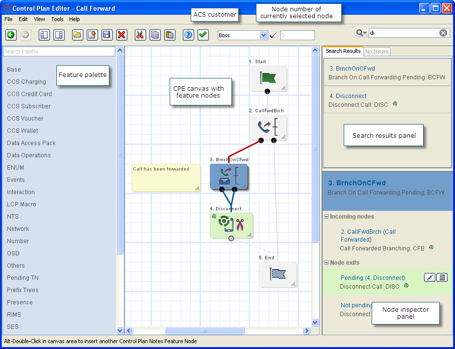
The CPE is divided into four main areas:
- On the left of the UI is the feature palette, which contains the names
of feature groups. A feature group is a set of feature nodes that are related to a common
function. Float your cursor over the feature group name to display the feature nodes in the
group. You can filter which feature nodes are displayed by using the
Search
          Palette
box at the top of the feature palette panel. For information about filtering the feature palette, see About Searching for Feature Nodes in the Feature Palette . - In the center is the CPE canvas where you build your control plans. You drag feature nodes from the feature groups to the control plan canvas. All control plans begin with a Start feature node. Each path in a control plan must end with an End feature node.
- On the right of the UI is the search results panel containing the Search Results tab and the Issues tab:
- The search results lists the feature nodes found in the canvas when you perform a search. For more information about searching the canvas, see About Searching for Feature Nodes in the CPE Canvas .
- The Issues tab displays information about any unresolved issues that may prevent the control plan in the canvas from compiling. It displays the number of issues, a list of the feature nodes that have unresolved issues, and a description of each issue. The list updates automatically as you resolve the issues in the control plan. For more information about control plan validation, see About Control Plan Validation .
- Below the search results panel is the node inspector panel. This displays information about the feature node currently selected in the canvas and lists its connections to other feature nodes. Buttons are displayed for the selected feature node that let you quickly access the feature node's configuration and add or edit comments for the feature node.
- In the toolbar area is the Customer list. This list displays the user name at the top and the names of the other ACS customer accounts you have permission to access. To the right of the Customer list is the Node field, which displays the number of the feature node that is currently selected in the control plan canvas. Each feature node is assigned a sequential number when you add it to the canvas.
About Control Plan Editor Search Features
About Searching for Feature Nodes in the Feature Palette
You can filter the feature nodes that are displayed in the CPE feature palette so that it is easier to find the feature nodes you want to add to a control plan. The CPE filters the feature palette by matching the text you enter in the Search Palette text box against the following data:
- Feature node name
- Feature node fast key: Fast keys are abbreviations for feature nodes and are displayed after the feature node name in the search results and the node inspector.
- Feature node configuration parameter names
- Feature node exits
For example, if you enter "en" in the search field, the feature palette displays every feature node that contains "en" in either its name, fast key, configuration parameter, or node exits.
About Searching for Feature Nodes in the CPE Canvas
You can search the CPE canvas for feature nodes that you have added to a control plan. You enter the search criteria in the canvas search field. The search criteria can be:
- Feature node properties, such as the feature node's name or type
- Unconfigured feature nodes
- The names of feature node configuration parameters
- Number prefixes used in geographic routing. This is useful for finding feature nodes that may have been configured to route calls to the wrong number. For more information, see About the Geo-Routing Search Feature.
The search results are displayed in the CPE search results panel. You can select a feature node in the search results to display information about it in the node inspector. For example, you can find out:
- Which incoming feature nodes it is connected to
- Which outgoing feature nodes it is connected to
- Whether it has any unconnected exits
About the Geo-Routing Search Feature
Geographical routing is implemented by the Geographical Routing feature node. You can search control plans for Geographical Routing feature nodes that route calls based on a specific number prefix. This will help you to find Geographical Routing feature nodes that have been configured to route to the wrong number.
When you search the CPE canvas for geo-routing number prefixes the CPE only looks for Geographical Routing feature nodes that route the specified number prefix through a non-default exit of the feature node. You designate which exit will be the default exit in the Geographical Routing feature node's configuration. The default exit will be taken if the call does not use one of the configured number prefixes.
Example Scenario for Using a Geo-routing Search
In this example, you, as the operator, have a pizza retailer customer who owns a pizza chain. The customer provides toll free numbers to the chain's pizza shops. The customer has a large control plan consisting of hundreds of feature nodes. The control plan structure uses:
- A series of Geographical Routing feature nodes that branch to different collection areas. Each collection area defines the geographic area that a particular pizza shop is responsible for, and the group of fixed line number prefixes for that area. You configure these prefixes in the geography sets assigned to the Geographical Routing feature nodes.
- Unconditional Termination feature nodes that connect calls from pizza customers to the appropriate pizza shop based on the collection area.
After the control plan is activated, a pizza shop customer attempts to call his local pizza shop and is instead connected to a pizza shop in a different area. The customer contacts the pizza retailer to complain. The pizza retailer contacts you about the issue and provides the number that the pizza customer dialed. You use the prefix of the dialed number in a geo-routing search of the control plan to find the Geographical Routing feature node that is routing that prefix. You then correct the configuration for that feature node so that it routes calls to the correct pizza shop.
About Troubleshooting Control Plans Using Control Plan Tracing
About Control Plan Tracing
A control plan trace is a type of CPE canvas search that finds which feature nodes in a control plan are referenced during a session by the service-logic processing. You enter control plan trace data in the canvas search field. This can make it easier to locate control plan errors.
The search criteria for a control plan trace is one or more feature nodes. You enter the search criteria in the canvas search field. The search criteria syntax matches the syntax that is used in CDRs to identify which feature nodes were referenced during the session. This makes it easy for you to copy data from a CDR into the search field without having to modify the data.
The search string must have the following syntax:
fastkey-number,fastkey-number,
where:
- fastkey is the short code used by the CPE for the feature node. For example, AT is the Attempt Termination feature node fast key.
- number is the number assigned to the feature node in the control plan.
The CPE performs the following actions to trace a session:
- Searches the control plan in the CPE canvas for all the feature nodes listed in the search string.
- If the CPE finds all the listed feature nodes and they are connected in the order listed in the search string, then the CPE highlights the feature nodes and the connections between them in the canvas. Otherwise the CPE returns no nodes found.
- Lists each feature node it finds in the search results.
In the search results you can step through the feature nodes found by the control plan trace and make any changes that are needed.
If you include a feature node in the search criteria that is not part of the service logic for the session you are tracing, then the CPE returns no feature nodes found.
Control Plan Trace Example
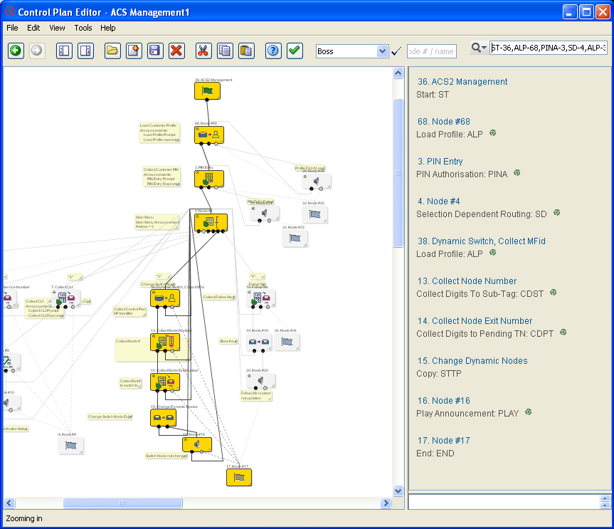
This example shows the feature nodes highlighted in the ACS Management control plan after entering the following control plan trace search string:
ST-36,ALP-68,PINA-3,SD-4,ALP-38,CDST-13,CDPT-14,STTP-15,PLAY-16,END-17
Accessing the Control Plan Editor
Accessing the CPE
You access the CPE from the Advanced Control Services (ACS) user interface. You can open the ACS UI either directly from a Web browser or from the Service Management System (SMS) user interface.
For instructions on how to log in to the SMS UI, see the discussion on signing on to SMS in SMS User's Guide.
For instructions on how to open the ACS UI, see the discussion on accessing ACS in ACS User's Guide.
To access the ACS user interface, you need to obtain the following from a system administrator:
- Your customer name
- Your user name
- Your password
- The URL of the SMS or the server host name of the SMS
Your user ID will be associated with access permissions that determine which parts of the ACS and CPE you can see and which actions you can take. All of the actions described in this guide may not be available to you. For more information about access permission levels, see About Access Permission Levels .
From the ACS UI main window, you can open the CPE in the following ways:
- Click Control Plans. This action directly opens the CPE where you can create or modify control plans.
- Click Numbers. This action opens the ACS Numbers window from which you can open the CPE. You use the Numbers window when you want to create or modify control plan templates or create control plans from an existing control plan template. You can also open the CPE from the Numbers window to create new control plans. For information about control plan templates, see About Control Plan Templates . For information about creating control plan templates, see the discussion of templates in the ACS Numbers section of ACS User's Guide.
About Access Permission Levels
Your ACS user access permission level determines whether you have permission to view, edit or create control plans. ACS user access permissions are configured by the System Administrator who sets up customers.
This table lists the control plan options available in the CPE for the different ACS permission levels.
| Control Plan Options | Permission Levels |
|---|---|
| Open public and private control plans as read only to view the control plan structures and data. | 1 and 2 |
| Open public and private control plan structures as read only, and create and edit the control plan data. | 3 |
| Open, create, and edit private control plan structures and data. Open public control plan structures as read only. | 4, 5 and 6 |
| Open, create, and edit private control plan structures and data. Open, create, and edit public control plan structures. | 7 |
For more information about access permissions, see the discussion on defining security levels in ACS User's Guide.