A.1 SWITCH REPLACEMENT
Table A-1 SWITCH REPLACEMENT
| STEP # | This procedure is for replacing the Telco switch with the Cisco switch. Check off (√ )each step as it is completed. Boxes have been provided for this purpose under each step number. IF THIS PROCEDURE FAILS, CONTACT MY ORACLE SUPPORTAND ASK FOR ASSISTANCE. | |
|---|---|---|
|
The following tools are required to perform this procedure:
|
||
|
1. ☐ |
Disable and disconnect switch power |
Tools required: Ground Strap, #2 Phillips Screwdriver, Multi Meter, and Diagonal Wire Cutter a. At the fuse panel, locate the fuse positions for the switch being removed. To power down the Switch, remove the fuses for both A and B feeds. b. Once the switch is off, unscrew and remove the terminal-block insulator covers from both terminals blocks A and B. c. With covers removed, using a Multi Meter, ensure that there is no power. d. Ensure that the power leads are marked -48V & RTN. e. With the cables marked, one at a time, remove the power cable and tape the terminal ring. Repeat these steps until all power connections are removed. 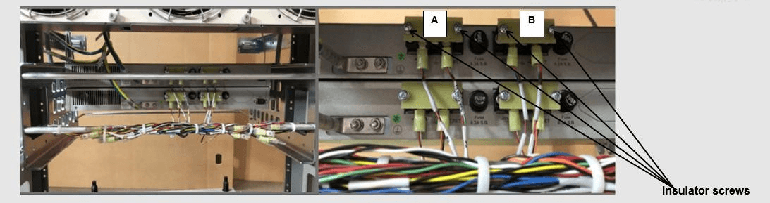 Note: This procedure will reference replacing the Switch #1 location (top). Same procedure is applicable for other switch locations. 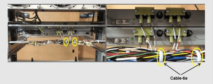
Note: For the replacement switch, if required, more cable slack/length can be added if the cable-ties are cut from the Tie-rod. See Step 8. |
|
2. ☐ |
Disconnect ground cable from switch |
Tools required: Ground Strap and 5/16" Nut Driver or Socket a. Remove the Switch Ground Wire from the grounding point, by loosening and removing Hex nut, Flat washer, and External tooth washer. b. Leave Ground Wire dangling. Do not disconnect ground wire attached to cabinet/frame. Note: Hardware removed, nut, and washers are NOT required on the replacement switch. 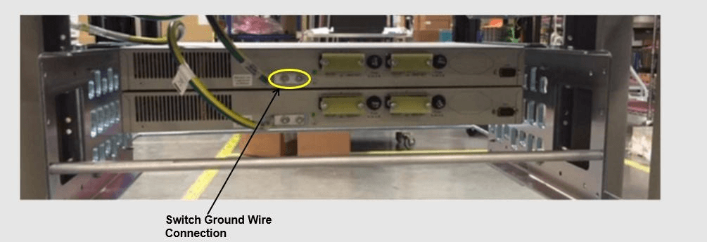 |
|
3. ☐ |
Disconnect Front ENET and Console Cables |
Tools required: Diagonal Wire Cutters Note: This procedure will reference replacing the Switch #1 location (Top). The same procedure used for other switch locations. a. Make sure that all the cables are labeled and are in the correct position that they are terminated at. If not, ensure to mark or label before starting any removal. b. Disconnect the Console and Ethernet cables from Telco switch being replaced. Leave the cables dangling. c. (Optional) If cable management tie-rod is mounted to the switch being replaced, it may be necessary to cut or remove the cable-ties, holding the cables from the Tierod. 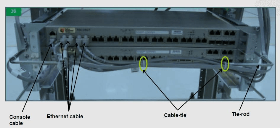 |
|
4. ☐ |
Remove the Switch being replaced |
Tools required: Ground Strap and #3 Phillips Screwdriver a. Remove the four (4) PAN head screws (Two (2) on either side of the switch). If there is no support under the switch, take care to support the switch while removing the screws. b. Remove the Switch from the Eagle rack. c. Keep the screws safely set aside. Required for mounting the new switch. Note: If Tie-rod is attached via the screws being removed, then the Tie-rod needs to be set aside for reattachment when the replacement Switch is installed. 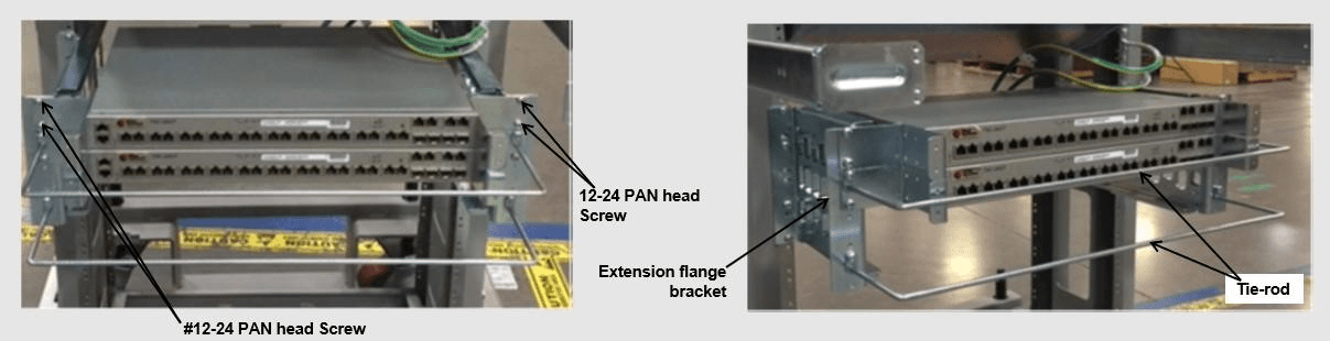 |
|
5. ☐ |
Assemble the replacement Cisco Switch |
Tools required: Ground Straps and #2 Phillips Screwdriver Attach the mounting brackets with Cisco switch assembly. a. Locate the supplied mounting brackets and screws from the Switch package. 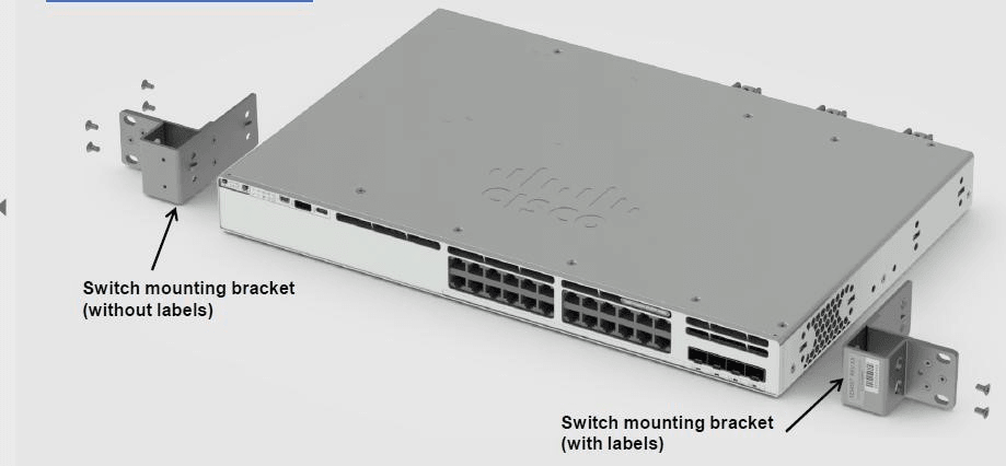 b. Align the mounting bracket to the switch using four mounting holes. Note: Bracket with labels to be mounted on the right side of the switch. c. Insert four screws, supplied with each switch, and tighten. 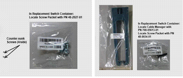 d. Repeat the steps b and c for the other side of the switch. e. Attach optional Cable Manager. I. Locate Cable Manager and Screw from replacement Switch packaging. II. Attach the Cable Manager to the rack mounting bracket using the supplied screw. 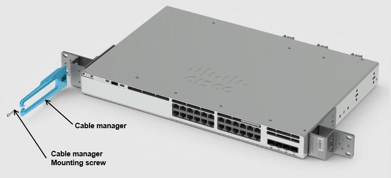 |
|
6. ☐ |
Install Replacement Cisco Switch |
Tools required: Ground Straps and #3 Phillips Screwdriver a. Align Replacement Cisco Switch in the slot where the original switch was removed. 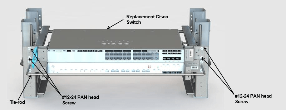 b. Using screws removed from step 4, insert the four (4) PAN head screws (Two (2) on either side of the switch) and tighten. Note: If Tie-rod was removed in step 4, reattach at this time. |
|
7. ☐ |
Reattach the ground cable |
Tools required: Ground Straps and #2 Phillips Screwdriver Reattach the chassis ground wire (from Step 3) to switch where shown. Use Screws provided with replacement Cisco Switch. 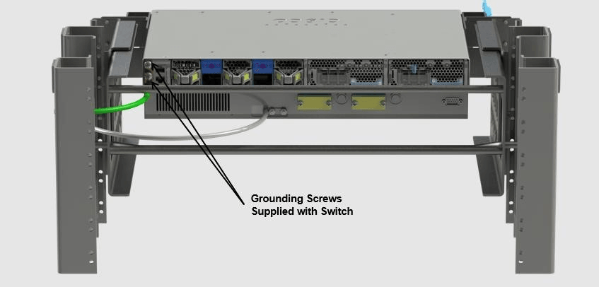 In Replacement Switch Container, locate grounding screw packet with PN 48-2381-01. 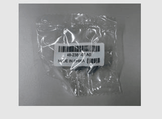 |
|
8. ☐ |
Connect power to the replacement Cisco Switch |
Tools required: Ground Strap and 1/4” Nut Driver a. Remove terminal block cover. 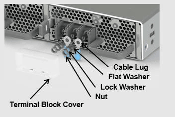 b. Remove Nuts and Washers from studs on A feed terminal block. c. Install the lugs from the power cable (A) to switch terminal block A. d. Secure the nuts after inserting flat washer and lock washer on top of the cable lug. e. Ensure connections to terminal block are as follows: SW RTN wire to "+" terminal, SW -48V wire to "-" terminal. 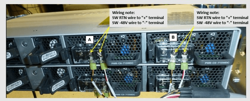 f. Reattach protective cover. g. Repeat the above steps for the B feed connection. |
|
9. ☐ |
Reattach Console Cable and Ethernet Cables |
Tools required: Ground Strap a. Plug-in the console port cable to the Replacement Switch. 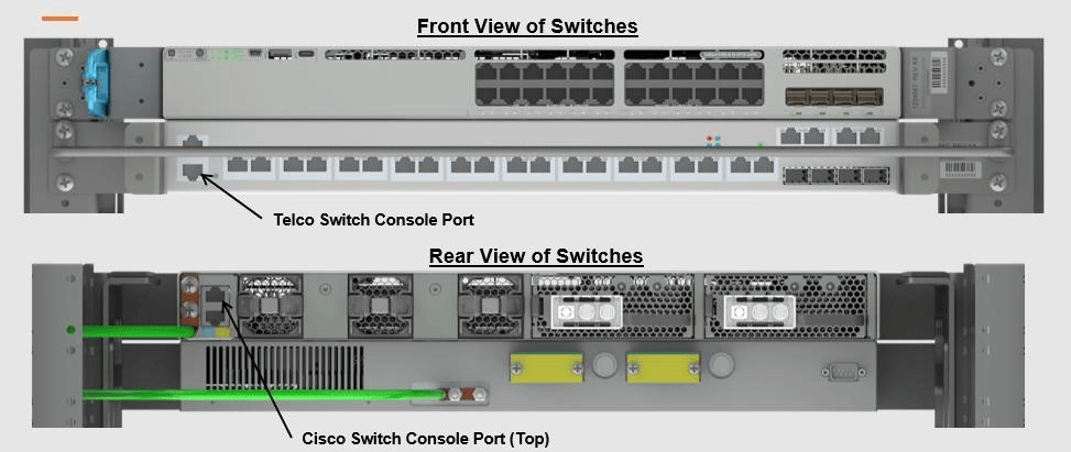 Note: The Console port on the New Cisco Switch is on the rear side where the power is applied. b. Plug-in the Ethernet cables to Replacement Cisco Switch. Note: The Switch locations are marked on cable from Step 3. |
|
10. ☐ |
Reapply power |
a. Double check all the connections are in their proper place and are secure. b. Reinstall the A and B feed power fuses (removed in Step 1) one at a time. c. Check the switch power supply LED to ensure power is up. Then, install the other fuse and again check power supply LED. 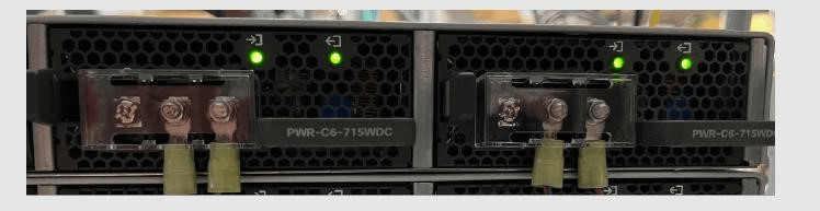 The replacement switch is now ready to be set up and configured. |
|
11. ☐ |
Configure the new Cisco Switch |
Refer to the following procedure “Switch Configuration” to configure the new Cisco Switch. |