Enhanced eSRVCC Call Continuity
As the LTE Evolved Packet Core (EPC) continues to expand, voice deployments (VoLTE) appear more and more, with the Oracle SBC and P-CSCF playing key roles. 3GPP standards that define how LTE communications take place also continue to evolve, identifying and solving critical issues to increase effectiveness and efficiency. One such issue is session continuity, keeping session transfers between LTE and existing 2G and 3G networks as seamless as possible. Single Radio Voice Call Continuity (eSRVCC) offers one solution for the session continuity issue.
In its role as the P-CSCF and IMS-GW, the Oracle Communications Session Border Controller can provide eSRVCC by acting as signaling and media anchor points to handover calls to 3G networks smoothly. These anchoring points are called Access Transfer Control Function (ATCF) and the Access Transfer Gateway (ATGW), both of which are logical additions to the Oracle Communications Session Border Controller’s IMS support.
The behavior of these two anchoring points, ATCF and ATGW, is defined by 3GPP in Release 12 of Technical Specification TS 24.237. Oracle Communications developed these functional entities based on the initial version of TS 24.237 Release 10. To align with Release 12, Requirement 4944 introduces the following two new elements to the functional design:
Handsets and Session Continuity
Session continuity can be effected by handsets, which can be dual-mode (3G+WiFi and 3G+WiMAX, for example). Such a handset has two receivers or radios to initiate calls simultaneously. An LTE handset has only one receiver and is able to attach to a single LTE or 3G network at a given time.
The question of session continuity appears in 3GPP standards Release 8, 9, and 10—each building on the previous. Release 8 defines Single Radio Voice Call Continuity (SRVCC) as the mechanism for moving active voice sessions between LTE and existing 2G or 3G circuit networks. In moving over sessions such as these, it is key to keep latency as low as possible to increase the possibility of successful handovers.
Release 9, because of variable signaling latencies within the core network, could not guarantee smooth handovers to circuit networks. And though IMS provides great flexibility in locating application servers remotely from the UE, that flexibility actually increases the latency in signaling media changes to the access network. Due to the high total signaling latency and the difficulty of successfully coordinating handover timing between 3G and 4G call legs, the possibility of call drops increased.
Anchors for Signaling and Media
Release 10 addresses the latency concern by proposing these two logical entities, the anchoring points called the ATCF and ATGW. The Oracle Communications Session Border Controller (SBC) can fulfill the tasks set to both entries:
- ATCF—A signaling anchor
point co-located with the UE access network. The ATCF is responsible for:
- Allocating the Session Transfer Number for Single Radio (STN-SR).
- Instructing the ATGW to anchor the media path for originating and terminating sessions.
- Tracking sessions (in alerting, active, or held states) so it can perform the access transfer of the selected session. Tracking this information allows the ATCF to support transferring the first session.
- Performing Access Transfer and updating the ATGW with the new media path for the access call leg, without requiring updating from the remote leg.
- After the access transfer, updating the Service Centralization and Continuity Application Server (SCC AS) that the transfer has taken place, ensuring that the Terminating Access Domain Selection (T-ADS) has updated information about the access currently used.
- Handling failures during the access transfer.
- Handling mid-call support for the access transfer using MSC server-assisted mid-call support.
- Access Transfer Gateway (ATGW)—A media anchor point co-located with the UE access network. Controlled by the ATCF, the ATGW anchors media both for the duration of a call and after the access transfer, based on the local configuration in the serving network.
Originating and terminating sessions are anchored in the ATCF and ATGW already during session set-up. For the first transferred session and the second established session, the SCC-AS provides session state information for the alerting, held, and conference states.
When a UE makes or receives a call, signaling and media are anchored at the ATCF and ATGW. At the point call handover point, the Visited-Mobile Switching Center (V-MSC) receives the handover message from Mobility Management Entity (MME, an EPC network element). The V-MSC then sends a call request to the local ATCF rather than sending the call request home or to the SCC-AS, as defined in 3GPP Release 8. Sending the call request to the ATCF reduces the number of hops required to initiate a media stream change to a new access network.
Acting as the ATGW, the SBC can immediately affect media switchovers without further core signaling. In this role, the SBC keeps RTP media continuity between endpoints using its Hide Media Update (HMU) functionality: The elements on the core side of the eSRVCC update will not see changes to SDP sources and destinations because the Synchronization Source identifiers (SSRCs) are masked. Media can thus flow directly to and from the 3G-attached MSC and onward to the UE with minimal interruption.
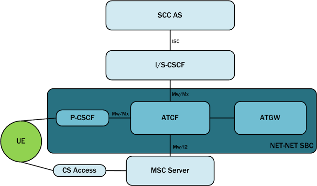
Note that if the MSC server-assisted mid-call feature is not supported or MSC server is not enhanced for ICS support, the interface between the MSC server and the ATCF will be Mw. If the MSC server-assisted mid-call feature is supported or the MSC server is enhanced for ICS, the interface between the MSC server and the ATCF will be I2.
Architectural View
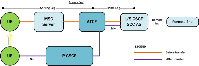
This diagram is an architectural view of the control and user planes, depicting communication both before and after transfer. This depiction assumes the PGW and the P-CSCF are in the serving network and support IMS voice roaming (if not the home network). So, the ATCF resides in the serving networking (home network if not roaming). The access leg of the session is divided into the serving leg and home leg. In an actual network, there might be other server IMS nodes.
IMS Registration Details
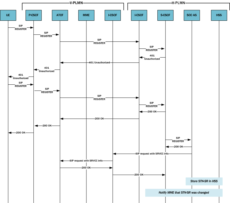
This section discussed the IMS registration process when a UE attempts to register with the home network, but must do so using an ATCF/P-CSCF. Based on the operator policy and the home network’s support for eSRVCC, the ATCF allocates an STN-SR to the session and includes itself in the signaling path for subsequent registration-related messaging. To understand whether or not the home network supports eSRVCC, the ATCF uses service-level agreements and can also determine if eSRVCC is activated in the SCC AS by the reception of a C-MSISDN/ATU-SI during session start-up.
If the ATCF generates an STN-SR, it includes the STN-SR in requests it forwards to the I/S-CSCF. The path and route information for the SIP REGISTER request sent to the S-CSCF is:
- Path—ATCF URI for
terminating requests (uniquely identifies registration or registration flow),
followed by P-CSCF URI for terminating requests.
The header field containing the ATCF URI for terminating requests contains the g.3gpp.atcf media feature tag (indicating this URI supports the ATCF role). This tag contains the STN-SR and the ATCF PSI, showing this URI can receive SIP message requests with SRVCC-related information.
- Route—URI of the entry point of the UE’s home network.
The ATCF tracks existing registrations for the UEs it has served. Each registration is identified by the P-CSCF path URI. The following information remains in the ATCF’s registration cache: the S-CSCF service route URI, the ATU-STI, and the C-MSISDN. When a UE’s registration expires or it is de-registered, the ATCF can remove any SRVCC information bound to the registration.
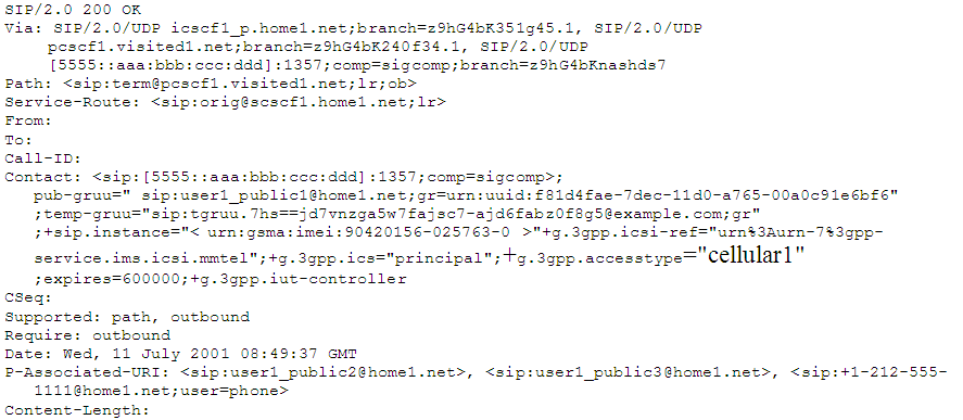
This ladder diagram shows the IMS registration process between these entities:
- The Visited Public Land Mobile Network (V-PLMN)—The network a mobile subscriber uses when that subscriber is roaming.
- The Home Public Land Mobile Network (H-PLMN)—The mobile subscriber's home network.
SIP Register Request UE to ATCF
The following is an example of the SIP REGISTER request the UE sends to the ATCF/ P-CSCF.
REGISTER sip:home1.net SIP/2.0
Via: SIP/2.0/UDP [5555::aaa:131313:ccc:eee];comp.sigcomp;branch=z9hG4bRnasiuen8
Max-Forwards: 70
P-Access-Network-Info: 3GPP-UTRAN-TDD; utran-cell-id-3gpp=234151DOFCE11
From: <sip:user1_public1@home1.net>;tag=2hiue
To: <sip:user1_public1@home1.net>
Contact: <sip:[5555::aaa:bbb:ccc:eee];comp=sigcomp>;+sip.instance="<urn:gsma:imei:90420156-
    025763-0>;+g.3gpp.icsi-ref="urn%3Aurn-7%3gpp-service.ims.icsi.mmtel"
Call-ID: E05133BD26DD
Authorization: Digest username="user1_private@home1.net", realm="registrar.home1.net", nonce="",
    uri="sip:home1.net", response=""
Security-Client: ipsec-3gpp; alg=hmac-sha-1-96; spi-c=23456789; spi-s=12845678; port-c=1234;
    port-s=5678
Require: sec-agree
Proxy-Require: sec-agree
CSeq: 1 REGISTER
Supported: path, gruu
Content-Length: 0
SIP Register Request ATCF to S-CSCF
The following is an example of the SIP REGISTER request the ATCF sends to the S-CSCF.
REGISTER sip:homel.net SIP/2.0
Path: <sip:termsdgfdfwe@actf.visited2.net>;+g.3gpp.atcf="<tel:+1-237-888-9999>";+g.3gpp.atef-
    psi="<sip:actf.visited2.net>",<sip:aga2gfgf@pcscfl.visited2.net:5070;ob>
Route: <sip:icscf.homel.net;lr>
P-Visited-Network-ID:
P-Charging-Vector:
Via: SIP/2.0/UDP actf.visited2.net:5060;branch=z9hG4bKnas5889; SIP/2.0/UDP
    pcscfl.visited2.net:5060;branch=z9hG4bKnas56565, SIP/2.0/UDP
    [5555::aaa:bbb:ccc:eee];comp=sigcomp;branch=z9hG4bKnasiuen8;rport=5060;received=5555::aaa:bbb:ccc:eee
Max-Forwards: 68
P-Access-Network-Info:
From:
To:
Contact:
Call-ID: Authorization:
Require:
Proxy-Require:
CSeq:
Supported:
Content-Length:Originating Sessions for SRVCC with ATCF
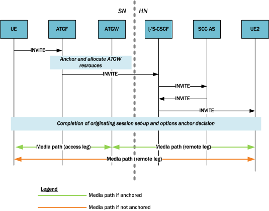
For initial SIP requests, the ATCF distinguishes SIP INVITE requests with the ATCF URI for originating requests in the topmost Route header field. And when receiving such an originating SIP INVITE request, the ATCF will do the following prior to forwarding it:
- Insert the Record-Route header field with its own SIP URI.
- If the latest SRVCC
information received for a session contains a C-MSISDN and ATU-STI:
- The ATCF will associate the session being established with the C-MSISDN and ATU-STI bound to the registration.
- The ATCF will replace the SDP offer in the originating SIP INVITE with updated SDP the ATGW provides. Replacement occurs if the originating SIP INVITE contains SDP and a determination to anchor media has been made (according to the operator policy as specified in the 3GPP standard).
Terminating Sessions for SRVCC with ATCF
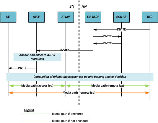
For initial SIP requests, the ATCF identifies SIP INVITE requests with the ATCF URI for terminating requests in the topmost Route header field. These are called terminating SIP INVITE requests.
When it receives a terminating SIP INVITE, the ATCF does the following if the INVITE has a Record-Route header field with the g.3gpp.srvcc media feature tag:
- The ATCF inserts a Record-Route header field with its own SIP URI
- If the latest SRVCC
information received for a session contains a C-MSISDN and ATU-STI,
- The ATCF associates the session being established with the C-MSISDN and ATU-STI bound to the registration, and
- The ATCF replaces the SDP offer in the originating SIP INVITE with updated SDP provided by the ATGW. Replacement occurs if the terminating SIP INVITE contains an SDP offer and a determination to anchor media has been made (according to the operator policy as specified in the 3GPP standard).
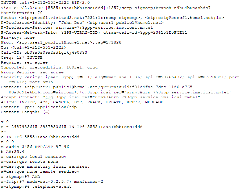
SIP INVITE from UE2 ATCF
The following is an example of the SIP INVITE UE2 sends to the ATCF/P-CSCF.
INVITE <sip:user1_public1@home1.net;gr=urn:uuid:f81d4fae-7dec-11d0-a765-00a0c91e6bf6> SIP/2.0
Via: SIP/2.0/UDP sccas1.home1.net;branch=z9hG4bKnas34r5
Max-Forwards: 67
Route: <sip:scscf1.home1.net:lr>
P-Asserted-Identity: <tel: +1-237-555-2222>
P-Charging-Function-Addresses: ccf=[5555.1399:c88:d77:e66]; ccf=[5555::a55:1344:c33:d22];
    ecf=[5555::1ff:2ee:3dd:4ee]; ecf=[5555.6aa:7bb:8cc:9dd]
P-Charging-Vector: icid-value="AyretyU0dm+602IrT5tAFrbHLso=023551024"; orig-ioi="type3home1.net"
P-Access-Network-Info:
Privacy: none
From: <tel: +1-237-555-2222; gr=hdg7777ad7aflzig8sf7>;tag=171828
To: <tel:+1-237-555-1111>
Call-ID: cb03a0s09a2sdfg1kj490333
Cseq: 127 INVITE
Supported: 100re1, precondition
Require: sec-agree
Proxy-Require: sec-agree
Security-Verify: ipsec-3gpp; q=0.1; alg=hmac-sha-1-96; spi=87654321; port=7531
Contact: <sip:user2_public1@home2.net;gr=urn:uuid:2ad8950e-48a5-4a74-8d99-
    ad76cc7fc74>;+g.3gpp.icsi-ref="urn%3Aurn-7%3gpp-service.ims.icsi.mmtel"
Allow: INVITE, ACK, CANCEL, BYE, PRACK, UPDATE, REFER, MESSAGE
Accept: application/sdp, application/3gpp-ims+xml
Content-Type: application/sdp
Content-Length: (...)

v=0
o=- 2987933615 2987933615 IN IP6 5555::aaa:bbb:ccc:ddd
s=
c=IN IP6 5555::aaa:bbb:ccc:ddd
t=0 0
m=audio 3456 RTP/AVP 97 96
b=AS:25.4
a=curr:qos local sendrecv
a=curr:qos remote none
a=des:qos mandatory local sendrecv
a=des:qos none remote sendrecv
a=rtpmap:97 AMR
a=fmtp:97 mode-set=0,2,5,7; mode-change-period=2
a=rtpmap:96 telephone-event
a=maxptime:20
m=message 0 TCP/MSRP 98
a=accept-types:text/plain
TS 24.237 Proposed Changes
The Oracle Communications Session Border Controller implements a proposed change in the processing of failed or cancelled SRVCC sessions. The new processing model has been presented to the 3GPP for inclusion in TS 24.237, IP Multimedia (IM) Core Network (CN) subsystem IP Multimedia Subsystem (IMS) service continuity; Stage 3.
Sections 12.2.4.13, 12.3.3.1, and 12.3.3.1A of 3GPP TS 24.237, IP Multimedia (IM) Core Network (CN) subsystem IP Multimedia Subsystem (IMS) service continuity; Stage 3, describe procedures in response to SRVCC handover cancellation. These procedures allow the UE to generate a e-INVITE request with the Reason header field containing a value of “SIP”, a “cause” parameter set to a value of “487” (Request Terminated), and with reason-text parameter set to a value of either “handover cancelled” or “failure to transition to CS domain”.
SCC AS processing, which does nor release the original access leg, is defined in Section 12.3.3.1 and subclause 12.3.3.1A. Section 13.3.1 describes the handling of subsequent UPDATE requests. There are, however, no defined procedures at the ATCF response to this scenario with the result that the ATCF fails to reconfigure the ATGW to reconnect the bearer in LTE.
Oracle Corporation, in conjunction with other interested parties has proposed the addition of a new Section 12.7.2.3.3 to TS 24.237. This section requires the following ACTF behavior.
Requirement 1: When the ATCF receives either a
- SIP BYE request on the Source Access Leg containing a Reason header field containing a SIP 503 (Service Unavailable) response code, that is terminating an established dialog or an early dialog on the Source Access Leg
- SIP CANCEL request on the Source Access Leg with the Reason header field containing a SIP 503 (Service Unavailable) response code then, that is terminating an early dialog on the Source Access Leg originated by the SC UE, or
- SIP 503 (Service Unavailable) response on the Source Access Leg, that is terminating an early dialog on the Source Access Leg terminating at the SC UE
Then -- The ATCF shall retain session state information and ATGW resources associated with the session until either it receives a SIP INVITE request due to STN-SR, or a specified time period elapses (default value is 8 seconds).
The session remains recognizable for SRVCC access transfer as described in Section 12.7.2.1.
The SIP BYE request is forwarded to the SCC AS, which also delays release of the session, as described in Section 12.3.3.2.
Requirement 2: If the transferable session set determined in Section 12.7.2.1 does not contain any sessions and the identity in the P-Asserted-Identity header field is a C-MSISDN that is not bound to a registration path in the ATCF, the ATCF shall respond with a SIP 404 (Not Found) response.
Requirement 3: When the ATCF receives a SIP re-INVITE request containing Reason header field containing protocol “SIP” and reason parameter “cause” with value “487” on the original source access leg,
-
after having initiated an access transfer that was triggered by a SIP INVITE request due to STN-SR, and
- the SIP INVITE request due to ATU-STI transaction is not yet completed
Then -- The ATCF shall wait until this transaction has completed and then continue with the steps described in Requirement 4.
Requirement 4: When the ATCF receives a SIP re-INVITE request(s) containing protocol “SIP” and reason parameter “cause” with value “487” after having performed an access transfer that was triggered by a SIP INVITE request due to STN-SR,
Then -- The ATCF shall act as B2BUA as described in Section 5.6 and shall.
- Interact with ATGW to provide information needed in the procedures below and to request ATGW to start forwarding the media from the remote UE to the local UE. The details of interaction between ATCF and ATGW are out of scope of this document.
- Send a SIP 200 (OK) response to the received SIP re-INVITE request. The SIP 200 (OK) response contains the SDP answer that includes the ATGW ports and the IP addresses as provided by the ATGW and the media used on the original source access leg as before the access transfer; and
- Forward the received reINVITE with the Reason header intact to the SCC AS on the existing source dialog with the SDP offer containing the ATGW IP addresses and ports towards the remote UE as provided by the ATGW.
This proposed behavior, which requires no user configuration) is implemented in Version S-CX7.2.0 and later releases.
Related call flows are shown below.
BYE before handover INVITE
Cancellation after handover complete.
Accounting
eSRVCC calls involve two SIP sessions, the accounting records for which need clear association. To correlate the records, the Oracle Communications Session Border Controller performs these actions for eSRVCC calls:
- When it detects a session handover, the system generates an Interim accounting record for the initial SIP session. This way, the records provide the exact time of the handover (i.e., the timestamp of the Interim record).
- The Oracle specific AVP Generic-ID will appear in Start, Interim, and Stop records for the handover SIP session. The Generic-ID contains the Call ID of the initial SIP session, which helps to correlate the two SIP sessions.
- For RADIUS accounting records, refer to Oracle specific VSA 40.
- For DIAMETER accounting records, refer to Oracle specific VSA 30.
- The Stop record for the initial SIP session will not have media flow information because the media session is considered part of the handover SIP session.
- If you are using QoS, the Stop records for the handover SIP session reflects the cumulative QoS statistics for both the initial SIP session and the handover SIP session.
External Bandwidth Management
Is you are using the Oracle Communications Session Border Controller's external bandwidth management for eSRVCC calls, note these considerations:
- At the time of handover and if the new handover realm has the same external policy server configured as the initial SIP session, the Rx will continue seamlessly with the same DIAMETER session identifier directed toward the policy server. From the perspective of the policy server, the same session is simply continuing.
- At the time of handover and if the new handover realm does not have an external policy server configured, policy server services will stop.
ATCF Configuration
ATCF functionality requires configuration in the sip-config and sip-interface configuration elements.
Continue to and select the existing sip-interface configuration element targeted for this ATCF configuration:
ORACLE(sip-config)# exit
ORACLE(session-router)# sip-interface
ORACLE(sip-interface)# select
<RealmID>:
1: public

selection: 1
ORACLE(sip-interface)#ATCF INVITE ICSI Matching
The Oracle Communications Session Border Controller can check, on reception of an INVITE on an ingress sip-interface that has a configured ATCF and before applying any of the already implemented logic, whether the incoming INVITE includes the ICSI (Instantaneous Channel-State Information) of the requested service. The ATCF will be involved in the call flow when the configured ICSI value matches the ICSI value in the original INVITE; otherwise the handoff call will be rejected with code 480 (Temporarily Unavailable) or 404 (Not Found).
The system looks for the ICSI string in the following headers:
- P-Preferred-Service
- P-Asserted-Service
- Feature-Caps (within the "g.3gpp.icsi-ref" feature-capability indicator)
- Accept-Contact (within the tag-value within the g.3gpp.icsi-ref media feature tag)
An example of the ICSI string in the P-Preferred-Service or P-Asserted-Service header is "urn:urn-7:3gpp-service.ims.icsi.mmtel". Examples of the ICSI string in the Feature-Caps or Accept-Contact headers are "+g.3gpp.icsi-ref="urn%3Aurn-7%3A3gpp-service.ims.icsi.mmtel" and "g.3gpp.icsi-ref="urn%3Aurn-7%3A3gpp-service.ims.icsi.mmtel". The ATCF will be involved in the call flow only when the ICSI matches. Configure the atcf-icsi-match parameter with the ICSI string you want to match. If atcf-icsi-match is blank, the check is not done and the behavior remains the same as before.
ATCF INVITE ICSI Matching Configuration
You can configure the Oracle Communications Session Border Controller to check, on reception of an INVITE on an ingress sip-interface that has a configured ATCF and before applying any of the already implemented logic, whether the incoming INVITE includes the ICSI (Instantaneous Channel-State Information) of the requested service and, if so, to involve the ATCF in the call flow.
