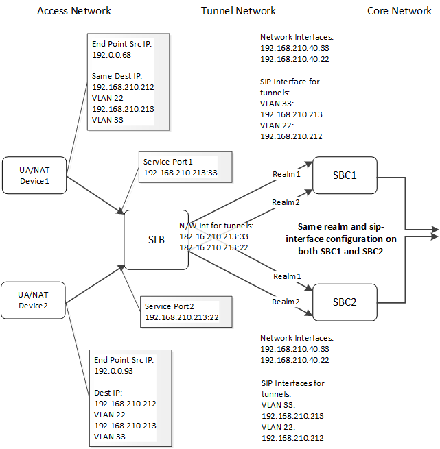
SLB VLAN Configuration
You can configure the SLB to use overlapping IP addressing between the access network and SBC clusters, supported by VLANs. When configured, the SLB includes VLANs within its ingress and egress traffic matching processes for policy-based load balancing. This allows it to operate within an access network that uses VLANs. These deployments also require applicable configuration on SBC cluster members. This feature is supported for both IPv4 and IPv6 addressing.
When you deploy an SLB cluster to support VLANs on the access network, you configure the SLB to recognize and retain VLAN association on its ingress (access) interfaces. The use of tunneling between the SLB and the SBC cluster members encapsulates this traffic, allowing the SLB/SBC load balancing function to operate exactly as it does within environments that do not use VLANs on their access networks. In addition, this architecture supports SLB control traffic operation that is independent of the service traffic.
Configurations that vary from deployments that do not use VLANs includes:
- Access Network—Configure the SLB service-port elements with the same IP/port/protocol, but with different VLANs.
- Tunnel Network:
- SBC—Configure sip-interface elements facing the SLB to separate realms using the realm-id parameters. This results in having one tunnel per sip-interface. This design scales to 250 tunnels.
- SLB—Configure global parameters for vlan-based-routing in the lbp-config and sip-config, and specify the applicable VLANs in the network-interface parameters of the service-ports. This design scales to 1250 tunnels.
- Core Network—No variations.
By using tunneling, you can configure the sip-interface elements that face the SLB identically on all SBCs in the cluster for each VLAN. You maintain unique IP addressing for the tunnels' outer packets on each network-interface. Each sip-interface can be thought of as having a “local instance” at the SLB. The connections to both realms on the SBCs represent the load-balancing mechanism driven by the configured load-balancing policy.

Service and CCP traffic is supported as follows:
- When it receives a SIP message at its service port, the SLB selects an SBC, encapsulates the IP
packet, and sends it using the correct network-interface IP
address. Upon reception, the SBC de-encapsulates the packet and processes the
message based on the inner IP packet.
The SLB directs incoming SIP messages to different SBCs based on their layer-3 source IP address. The SLB does not look at any IP addresses in the SIP message itself.
- Cluster Control Protocol (CCP) messages are not tunneled. These messages go between the SLB network-interface IP address and the network-interface IP addresses for each SBC in the cluster. The system only sends SIP traffic through tunnels.
Configuration
To deploy SLB in front of SBCs with OLIP, VLAN tagging on the service interfaces exposed to customer is required. To support VLANs, the SLB supports the same address, port and protocol with different VLAN. In addition, you must also configure cluster SBCs with the same VLAN that is configured on the SLB service port.
To enable this feature on the SLB, you first enable the parameter shown below, in the lbp-config, and reboot.
ORACLE(lbp-config)#vlan-based-routing enabledNext, enable the option shown below, in the sip-config, and reboot.
ORACLE(sip-config)#options +vlan-based-routingBeyond these global configurations, you configure sip-interface, network-interface and service-port as conceptually described above. Task steps and a sample configuration are provided below.
Note:
When operating the SBC as a PNF (ACME Packet platform), be aware that the default value for the arp-msg-bandwidth parameter is 32000. To handle ARP DOS thresholds within the context of this feature, configure arp-msg-bandwidth to 50000.To establish the same support when operating as a VNF (vSBC), set the max-arp-rate parameter to 30.